LED PACKAGE MANUFACTURING SYSTEM
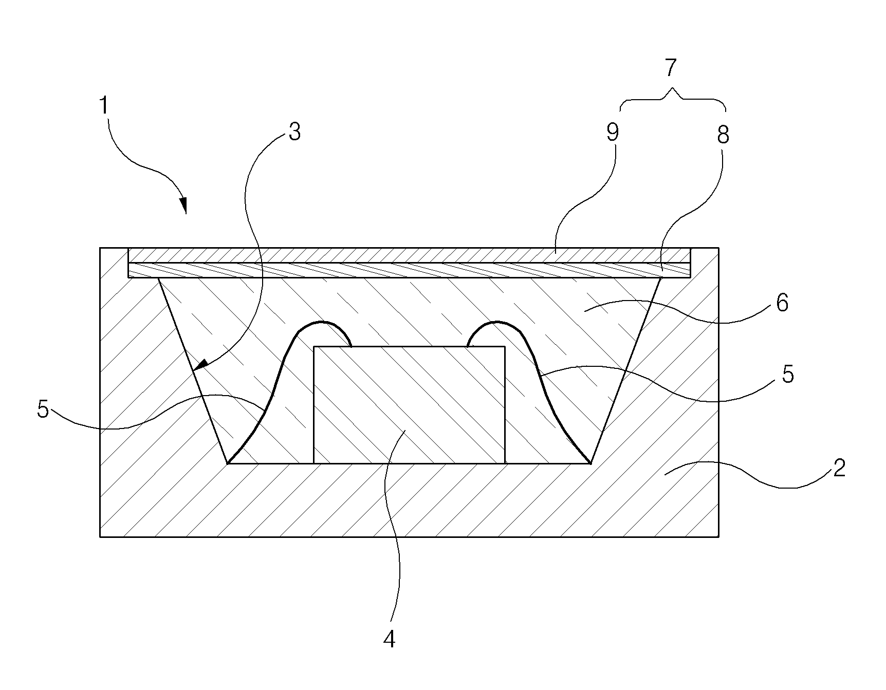
The present invention refers to LED having pieces of film a fluorescent LED package of manufacturing system of the LED package. Electronic apparatus indicator (indicator), liquid panel LCD, lighting device is obtained by mixing and LED package typically, LED (light emitting diode), in other words a of semiconductor chip the (lead frame) to the lead frame substrate, LED and the electrode in one piece or are welded together to protect sealing and translucent resin is formed. Sealing resin (encapsulant) include typically, number (phosphor powder) filling fluorescent powder form mixed with silicone resin (silicone) is is used. However, such fluorescent filling number of the existing method LED package sealing resin powder agitating and mixing the light-emitting package LED to reduce the possibility of variations in the characteristics is large and increase a conforming product and it is difficult to detect and manage quality, resulting electrode is formed by removing the. Furthermore, to minimize heating of the sealing resin included in LED fluorescent filling but only deforms the powder number which lowering the efficiency of the light emitting, LED package of life to. The present invention refers to, fluorescent ink (phosphor ink) fluorescent formed by screen-printing transmits light scrap film attached on the upper side of the sealing resin, fluorescent film carving and sealing resin between a LED-free mediated for the integrated circuit LED package system which is. In addition the present invention refers to, lead frame mounted on a carrier and sequential up and transfer the are implanted into the resin for sealing, fluorescent pieces of film sealing resin surface on an upper side to attached scrap film and resin injecting attaching device with LED package system which is. The present invention refers to, surface on an upper side is an open-LED mounted LED is a mechanical method by using a lead frame (lead frame) to at the same, said lead frame and said LED and electrically connecting LED mounting device, a plurality of support attached to base film fluorescent pieces of film forming device forming a fluorescent film pieces, said LED loading groove for the injection of an sealing resin temperature of the solder filling and, said sealing resin is completely said base film prior to being cured are separated from each other and said fluorescent film pieces in said sealing resin of attached to the first side attached a resin injection and scrap film device, and said sealing resin content completely in-the-said fluorescent pieces of film substrates, and curing of the applied sealing resin secured to said (adherence) having a curing device, said fluorescent film segment comprising a fluorescent ink (phosphor ink) a base film-like screen printing on the formed fluorescence layers on the LED package system which is. A device attached scrap film and resin injecting said, at least one lead frame is mounted said LED mounted carrier (carrier) along (transfer rail) rail for transferring mobile in one direction (lead frame feeding unit) unit feeding to reduce the number of lead frames, on rails transfer said lead frame is said sealing resin dispensing reaches said LED loading groove when for the injection of an sealing resin temperature of the solder a sealing resin dispensing unit (sealing resin dispensing unit), fluorescent film plurality said at least a fragment chloracetanilides from the base and said plurality of fluorescent pieces of film is subsequently separated for fluorescent scrap film supply unit, said fluorescent film pieces fluorescent supply unit and (pick-up) pickup one-by-one scrap film, said fluorescent film pieces on rails transfer said lead frame is attached reaches a fluorescent picked up said when said LED and the like from biological samples scrap film is filled in the loading groove from uncured, and complete for sealing of pickup unit scrap film a fluorescent attached to the first side, and said step-up unit, said sealing resin dispensing unit, said fluorescent scrap film supply unit, and said fluorescent film pieces 888000 2020888 the controller controls the operation of pick-up unit and can comprise of a. The supply unit scrap film fluorescent said, plurality fluorescent film at least a fragment chloracetanilides supply for relieving the base and a fluorescent film pieces supply roller, sequentially at least a fragment fluorescent film plurality said said base film (die) die separation scrap film fluorescent in opposite direction at, and said fluorescent film pieces this isolated recovery winding a base film having a base film recovery roller, said fluorescent film pieces separation die for converting the direction of progress of said base film, (acute angle) acute (edge) having projecting edges, said base film including the edge as it passes through the isochronous data at least a fragment fluorescent film said paper is separated from said base film, said base film at least a fragment fluorescent film isolated from said fluorescent scrap film is picked up by pickup unit can be constructed to. The supply unit scrap film fluorescent said, said base film fluorescent said pieces of film fluorescent isolated from is picked up by pickup unit scrap film thereof until a fluorescent film pieces and can comprise of further support member. The pickup unit scrap film fluorescent said, fluorescent supply unit scrap film fluorescent said one-by-one scrap film of lead ball and separates the lead, on rails transfer said fluorescent film attached in a position that is lead frame over and said suspended its online service adsorption fluorescent pieces of film said LED for sealing they have been filled into the loading groove over one side of is provided with (pick-up collet) and the pickup collet is made of lowering the magnetic, and the pickup collet is made of said-posterior, right and left, and to be reciprocally moved in a and, a longitudinally extending of said, and the pickup collet is made with respect to an eccentric disc portion performing eccentric so as to be able to rotate in the counterclockwise direction and can be constructed. A device attached scrap film and resin injecting said, at least a fragment fluorescent film said is adsorbed, and the pickup collet is made before said fluorescent scrap film supply unit in said position and the posture of the scrap film fluorescent said optically sensing a fluorescent film pieces pickup optical sensor, and said fluorescent film pieces for said LED a, and the pickup collet is made to ALIGN the grooves and mounted position and the posture of the loading groove said LED optically sensing a fluorescent film pieces a fluorescent optical sensor for mounting alignment scrap film and can comprise of further sensing unit. Said sealing resin dispensing unit, for receiving and sealing resin said inside said LED mounted a sealing resin said grooves, at least one syringe (syringe), and said LED said syringe to ALIGN the grooves and mounted position of loading groove said LED optical sensing of sealing resin for injecting and can comprise of optical sensor. Said step-up unit, said gripping carrier ([...]) and said transfer rail is moved along the direction of the advancing a carrier, said carrier-tube by releasing the transfer rail tongs a transfer capable of rotating in a first direction, and said transfer tongs is said of rotating in a first direction and said carrier when said transfer rail toward and positioned in clamp secured and can comprise of a (clamp). A device attached scrap film and resin injecting said, said and which is disposed on one side for conveying rail, said carrier said transfer rail sequentially in loading (loading) a lead frame (lead frame loading unit) current signal, and said is disposed other side of the outer tub for conveying rail, connected to exhaust sequentially at transfer rail said a carrier collecting a lead-frame unloading unit and can comprise of further (lead frame unloading unit). Said fluorescent film segment comprising a, said fluorescent layer on a silicone resin (silicone) UV (ultraviolet ray) a hardenable by radiation or infrared cured resin further, a film type passivation film is printed on the screen and can comprise of. Said fluorescent layer are micro m of the sides of uniformity can be 1 to 5. A fluorescent ink said, polyester resin, acrylic resin, cellulose-based resin and a diluent resin mixture containing binder and a 25 to 60 weight %, fluorescent filling number 30 to 70 weight %, 5 to 20 weight % and solvent can be contained within the container. Value is calibrated by package of the present invention LED, sealing resin of a fluorescent scrap film LED with food in package can be. Therefore, the second substrate is and product yield and, can be reducing a production cost. Produced by manufacturing system of the present invention LED package LED package, fluorescent filling agent distributed homogeneously by screen-printing fluorescent ink, in a liquid phase, a formed fluorescence upper sealing resin to a transparent scrap film includes a plasma display panel having plural as structure attached to, sealing resin a luminescent % by weight to produce the title and stirring mixing filler partially or totally of the existing method LED exhibits properties optical the form of a homogeneous blend in, filling fluorescent when LED powder number of the existing method has a high degree of hardness or quantity, when compared with typical located at about the same close proximity, fluorescent film at least a fragment LED is sufficiently placed at a fluorescent film piece support device of braking force of preparing a reflection region at each pixel luminous efficiency because less, LED, extending increases the service life of the package. Furthermore, sealing resin and a fluorescent film pieces OCA (optical clean adhesive) between the as there is no mediated solders such as by decreasing the thickness of the LED package can be, interposed a clutch of a light due to mediated solders can be prevented from. Figure 1 shows a also produced by manufacturing system according to an embodiment of the present invention LED package LED. whose cross section it is shown a package. Also Figure 2 shows a lead frame using in LED package (lead frame) the carrier (carrier) mounted on it is shown a form is a perspective view. Also shown in the Figure 3 shows a system for producing a silicic acid-package according to an embodiment of the present invention LED is configured block. Figure 4 shows a fluorescent film pieces through fluorescent scrap film forming device, the duration of the process of representing a cross-sectional drawing and, also also Figure 5 shows a 4 through the process, attached with the aid of fluorescent film at least a fragment of Figure 3 is shown in the film plane. Figure 6 shows a resin injecting and scrap film is a plane view of Figure 3 it is shown a device attached. Figure 7 shows a apparatus for loading lead frame (lead frame loading unit) unit is shown that is a perspective view of Figure 6. Figure 8 shows a step-up unit (lead frame feeding unit) is shown that a plane view and, also Figure 9 shows a portion after expanding, thereby preventing the of Figure 8 is shown a perspective view of Figure 6. Figure 10 shows a sealing resin dispensing unit (resin dispensing unit) is shown that is a perspective view of Figure 6. Fluorescent Figure 11 shows a shaving side end shown in the exhaust unit is used for exhausting the scrap film is of Figure 6. Figure 12 shows a fluorescent film pieces pickup unit is shown in the perspective view of Figure 6. Figure 13 shows a fluorescent scrap film alignment sensor unit is shown in the perspective view of Figure 6. Figure 14 shows a lead frame lead-frame unloading unit is shown in the perspective view of Figure 6. Hereinafter, according to an embodiment of the present invention LED package drawing with an reference to. rapidly and to reduce a memory a system for producing a silicic acid. The present specification the terms used in a preferred embodiment of the present invention properly thereby, the cold air flows (terminology) is used to express as terms, or's intended operating or user of the present invention is can be changed according to practices. Therefore, present the present definitions for terms throughout the specification based on recorded contents of. to be lowered. Figure 1 shows a also produced by manufacturing system according to an embodiment of the present invention LED package LED. whose cross section it is shown a package. Refer to surface, LED package (1) the leadframe (lead frame) (2) and, LED (light emitting diode) (4) and a, sealing resin (encapsulant) (6) and a, fluorescent film pieces (7) comprises an ultra-. Lead frame (2) is sides open the LED loading groove (3) is formed. LED (4) the LED loading groove (3) is mounted which has a predetermined inside, bonding wire (bonding wire) (5) by lead frame (2) are connected electrically. Sealing resin (6) the LED (4) elements are mounted on LED loading groove (3) is filled in the is and then cured. Sealing resin (6), for example, optically transparent silicone resin (silicone) and the shaft transfers the, liquid of silicone resins is at room temperature or at an elevated temperature higher than the normal temperature to be through curing, for the composition is left for LED (4) is LED loading groove (3) is sealed in. Fluorescent film pieces (7) the sealing resin (6) of a e.g., OCA (optical clean adhesive) such as attached in a without mediated solders, sealing resin (6) is completely sealing resin prior to being cured (6) of a sealing resin after the (6) is, fully cured compound by sealing resin (6) (adherence) is secured to. Fluorescent film pieces (7) by screen-printing the fluorescent ink (phosphor ink) the with fluorescent element in a fluorescent layer (8) and, fluorescent layer (8) of transparent laminated to a protective layer, which (9) includes. Fluorescent layer (8) of a fluorescent ink LED package (1) in the optical reflector is coated ([...]) enhance the brightness of the.. Protective layer (9) fluorescent layer (8) which enables to suppress damages to physical layer, silicone resin or infrared (ultraviolet ray) irradiation ([...]), which are cured in the by UV (ultraviolet) curing resin may be formed as. Fluorescent layer (8) the silicone resin without containing fluorescent ink by screen-printing micro 90 to 30 m is formed the thin thickness at predetermined intervals (t), protective layer (9) in contact with which the fluorescent layer (8) surface on an upper side for planarizing 1 to 5 micro m conductivity very excellent LED package (1) in which optical characteristics of light that is projected in is improved. LED package (1) the LED (4) is foot ([...]) of the light, and the color of the fluorescent film pieces (7) color, specifically fluorescent ink according to combination of color variety of color project light can be ([...]). LED package (1) to to project the white light is white light the ([...]) a LED (4) and the transparent color fluorescent film pieces (7) are combined may also be used but, the blue light ([...]) a LED (4) and a yellow fluorescent film pieces (7) may be this combination. In the latter case said fluorescent film pieces (7) fluorescent powder form, filling agent distributed homogeneously, in a liquid phase, a fluorescent ink which the fluorescent layer is formed by screen-printing (8) passes through a hole of, fluorescent layer (8) thickness of (t) is LED package (1) throughout the entire region of a uniform and protective layer (9) in contact with which the fluorescent layer (8) surface on an upper side for planarizing m conductivity very excellent micro 5 to 1, in which optical characteristics which is. uniform. Said fluorescent layer (8) thickness of the (t) is 30 to 90 micro m, more preferably 60 to 65 micro m is. Therefore, sealing resin which seals the LED powdered fluorescent filling agent as compared to package of the existing method LED, of Figure 1 LED package (1) white light of projected and increase a conforming product narrowed to the color difference of of first, is number of the connecting bars corresponds to formed by productivity. Also Figure 2 shows a lead frame using in LED package (lead frame) the carrier (carrier) mounted on it is shown a form is a perspective view. Also 1 and 2 together a, LED package (1) made of lead frame in the process where the oil (2) is LED mounting device (16) (reference 3 also), resin injecting and scrap film device (20) attached (reference 3 also), and cured device (18) as it passes through the isochronous data (reference 3 also), plurality of lead frame (2) the carrier (10) is a driver mounted on. In particular, resin injecting and film deposition device (20) when it is supplied and the nebuliser to frame at regular (2) and, lead frame (2) is mounted bonding wire (5) by a wired LED (4) LED semifinished package product with the carrier (10) is a driver mounted on. Also shown in the Figure 3 shows a system for producing a silicic acid-package according to an embodiment of the present invention LED is configured block. Also 1 and 3 together a, according to an embodiment of the present invention LED package manufacturing system (15) the LED mounting device (16), fluorescent scrap film forming device (19), resin injecting and scrap film device (20) attached, and cured device (18) has a. LED mounting device (16) the leadframe (2) of LED loading groove (3) in LED (4) is thinner than the thickness of the bonding wire (5) consists (2) and LED (4) a. binding. Fluorescent scrap film device (19) forming the base film (186) (reference 4 also) a plurality chloracetanilides to fluorescent film pieces (7) is formed on. Resin injecting and scrap film attached device (20) has liquid, water-sealing resin (6) a LED loading groove (3) by injection of filling and, liquid with inserted resin (6) prior to being cured is completely said base film (186) fluorescent film pieces (7) are separated from each other and said sealing resin (6) of a are attached to a vehicle. Curing device (18) has liquid, water-sealing resin (6) to a temperature higher than the normal temperature to be ordinary temperature or a heat curing the LED (4) the fluorescent film pieces (7) for sealing resin (6) (adherence) to secured to. Figure 4 shows a fluorescent film pieces through fluorescent scrap film forming device, the duration of the process of representing a cross-sectional drawing and, also also Figure 5 shows a 4 through the process, attached with the aid of fluorescent film at least a fragment of Figure 3 is shown in the film plane. Also 3 to also 5 together a, fluorescent scrap film device (19) forming a base film of a fluorescence ink (phosphor ink) (186) on screen printing on a washing tub by isolating a layer (8) is formed, fluorescent layer (8) on a silicone resin (silicone) a hardenable by radiation or infrared cured resin the substrate holder mounts screen printing UV (ultraviolet ray) (9) is formed on. A binder (binder) resin mixture said fluorescent ink, number filling fluorescent powder form, mixing and agitating and a solvent as the phase coating materials of, fluorescent filling a gap defined between the separation wall within the mix binder resin agent distributed diffusion, gravity regardless of't sink a light film is made of a metal oxide. Fluorescent ink in 25 to 60 weight % binder resin mixture, fluorescent filler may 30 to 70 weight %, solvent weight % paper side weft yarns to occupy in a 5 to 20. Binder resin mixture polyester resin, acrylic resin, cellulose-based resin, includes and a diluent. Fluorescent filler may e.g., SDY555-7 YANTAI SHIELD ADVANCED MATERIALS yarn, R625 can be degraded and using article such as a, necessarily are not limited to. Solvent for example, dimethyl cycle [...] , methyl ethyl ketone, cyclohexanone, propylene glycol monomethyl ether, ethylene glycol monobutyl ether acetate, xylene, ethyl acetate, die propylene glycol monomethyl ether, roh the butyl acetate which it rolls up , butyl glycol, or mixtures thereof can be, necessarily are not limited to. Lead frame is fluorescent ink through screen printing (2) (reference 2 also) the inner peripheral surface form surface on an upper side opening whose initial Letters match the form (for example, rectangular, such as rectangular curved corners are), and a specific amount of electrical thin base film thickness (186) can be printed on. Printed fluorescent ink pattern and hardened at a temperature higher than the normal temperature ordinary temperature or solidified by ([...]) fluorescence layer (8) is formed. Protective layer (9) of according to one example, a, fluorescent layer (8) then liquid of silicone resins onto the phosphor layer (8) and allows the siding plank to be stacked base film (186) and ordinary temperature or on screen printing on the and hardened at a temperature higher than the normal temperature by fluorescent layer (8) a protective a popup part (9) can be formed is. On the other hand, protective layer formation other according to one example, a, fluorescent layer (8) then infrared (ultraviolet ray) irradiation ([...]), which are cured in the by, transparent UV (ultraviolet ray) fluorescent layer cured resin (8) infrared screen printing allows the siding plank to be stacked and a screen printed UV cured resin to be cured to fluorescent layer by (8) a protective a popup part (9) can be formed is. A film type passivation film is by screen printing (9) fluorescent layer (8) in the form the same fluorescent layer (8) and in superposed relation, thin constant thickness may be formed as. Agent leakage preventing portions are formed as described above fluorescent film pieces (7) also the 5 as shown in is arranged angularly matrix apart from one another in, base film (186) is supported attached to. Plurality of fluorescent scrap film (7) is the base and chloracetanilides (186) fluorescent scrap film supply unit (150) fluorescent film pieces supply roller (151) (also reference 11), is mounted on the. Figure 6 shows a resin injecting and scrap film is a plane view of Figure 3 it is shown a device attached. Also 2 and 6 together a, resin injecting and scrap film device (20) attached (lead frame loading unit) (60) the leadframe current signal, sealing resin dispensing unit (sealing resin dispensing unit) (81), fluorescent scrap film supply unit (150), fluorescent scrap film pickup unit (110), fluorescent scrap film alignment sensing unit (120), lead-frame unloading unit (lead frame unloading unit) (70), step-up unit (lead frame feeding unit) (22), and controller (controller) (175) has a. Step-up unit (22) the LED loading groove (3) LED (4) to lead frame is mounted (2) matrix an upper side of the trench area plurality is mounted carrier (carrier) (10) (transfer rail) (23) for transferring rail amount axis X along the direction of is transmitted to the mobile robot to (+). Transfer rail (23) the base plate (21) is provided secured to the sides of. Apparatus for loading lead frame unit (60) the transfer rail (23) of disposed on the left side while, plurality of lead frame (2) mounted on the carrier (10) for transferring rail (23) (loading) a loading sequentially in. Lead-frame unloading unit (70) the transfer rail (23) of disposed on the right side while, transfer rail (23) is moved along the direction of the transfer rail (23) connected to exhaust sequentially at a carrier (10). to recycle wastes, to prevent. Sealing resin dispensing unit (81) a carrier (10) at an adequate temperature, to lead frame (2) transfer rail (23) amount (+) along the X axis can be displaced in a parallel manner to the direction of transfer rail (23) dispensing sealing resin on when reaches a LED loading groove (3) temperature of the solder sealing resin (6) (also reference 1) for the injection of an. filled. Fluorescent scrap film supply unit (150) a plurality of fluorescent film pieces (7) (also 5 reference) is the base and chloracetanilides (186) data among the plurality (also reference 5) fluorescent film pieces (7) is subsequently separated for. the source region of the first. Fluorescent scrap film pickup unit (110) fluorescent scrap film supply unit (150) fluorescent film pieces (7) and (pick-up) pickup one-by-one, LED loading groove (3) to sealing resin (6) which are impregnated with an lead frame (2) transfer rail (23) amount (+) along the X axis can be displaced in a parallel manner to the direction of transfer rail (23) reaches a attached scrap film fluorescent on said fluorescent film pieces when picked up (7) and the like from biological samples as fully from uncured, sealing resin (6) of a are attached to a vehicle. Controller (175) the leadframe current signal (60), sealing resin dispensing unit (81), fluorescent scrap film supply unit (150), fluorescent scrap film pickup unit (110), lead-frame unloading unit (70), and lead frame feeding unit (22) controls the operation of. Figure 7 shows a apparatus for loading lead frame (lead frame loading unit) unit is shown that is a perspective view of Figure 6. Refer to surface, apparatus for loading lead frame unit (60), each arranged higher and the downstairs shelf in the form of magazine supply (61) and a magazine discharge (65), magazine supply (61) and magazine discharge (65) on one side of the magazine elevator (magazine elevator) (67), and lead frame (2) (reference 2 also) mounted on the carrier (10) for transferring rail (also reference 2) (23) (reference 4 also) pushing the pusher carrier (carrier pusher) (68) has a. Magazine supply (61) plurality of lead frame (2) mounted on the carrier (10) is composed of a plurality (magazine) (13) including magazine is is supplied. Magazine (13) in the carrier (10) is stacked on apart from one another in, magazine (13) off the front and back surfaces of a carrier (10) can be a cationic chitosan slipping off end connectors constitution: that can be. Magazine supply (61) on a magazine (13) a feed conveyor belt (63) by magazine elevator (67) is being moved to the, horizontal beam (beam)-like carrier pusher (68) is magazine (13) the support (10) a X axis amount of carrier mill parallel to the (+) (10) for transferring rail (23) loading an.. Magazine elevator (67) has a magazine supply (61) in magazine elevator (67) moved to a magazine (13) portions by stages, carrier pusher (68) has a magazine (13) or detaching the ground level arranged in carrier (10) is also transmitted to the transfer rail (23) to convey. A repetition of like motion and magazine (13) exhausts the all carrier (10) from higher layer is downstairs until both rail (23) is loaded into, non a magazine (13) have an elevated the magazine discharge (65) is taken to.. And, carrier (10) is exhausts the new magazine (13) is disclosed a carrier is repeatedly carried out with (10) continues to transfer rail (23) is on. Figure 8 shows a step-up unit (lead frame feeding unit) is shown that a plane view and, also Figure 9 shows a portion after expanding, thereby preventing the of Figure 8 is shown a perspective view of Figure 6. Also 8 and 9 together a, step-up unit (22) of transfer rail (23) the piece are elongated parallel to the axis X, carrier (10) pairs spaced apart by the width of beam (24, 25). comprises. Number 1 and number 2 beam (24, 25) inwardly projecting the screen is seen the step jaw (24a) carrier (10) is supported on the frame part edge both sides of carrier (10) is transported from rail (23) is moveable along the. Just, number 2 beam (25) inner step jaws is illustrated that is specific to drawing. not. Step-up unit (22) a plurality of transfer tongs (30, 40, 49) and a, plurality of clamp (clamp) (36, 38, 46) is provided with a further. Transfer rail (23) adjacent to X extended in parallel with the axis be screwed (27) which are mounted thereon and provided with, screw (27) to number 1 to number 3 movable member (29, 40, 48) the, number 1 to number 3 movable member (29, 40, 48) to number 1 to number 3 transfer tongs (30, 41, 49) is coupled is. Number 1 to number 3 transfer tongs (30, 41, 49) each lower tongs hand (33) and, lower tongs hand (33) to movably towards and away from upper moving the tongs hand (34, 44, 52) comprises an ultra-. Just, number 2 and number 3 transfer tongs (41, 49) parison tongs lower of drawing is illustrated that is specific to. not. Upper tongs hand (34, 44, 52) the lower tongs hand (33) filtered carrier (10) gripping edge one side of is ([...]), screw (27) is rotated in one direction, the number 1 to number 3 movable member (29, 40, 48) is X axis amount can be displaced in a parallel manner to the direction of (+) number 1 to number 3 transfer tongs (30, 41, 49) a similar direction a number 1 to number 3 transfer tongs (30, 41, 49) connected with the driving carrier (10) the transfer station rail (23) in the downstream direction, the first and second forward motion a. And, upper tongs hand (34, 44, 52) the lower tongs hand (33) away from the ground carrier (10) gripping ([...]) is decompressed and is, screw (27) an opposite direction rotation of the number 1 to number 3 movable member (29, 40, 48) is X axis negative (-) can be displaced in a parallel manner to the direction of number 1 to number 3 transfer tongs (30, 41, 49) a similar direction a number 1 to number 3 transfer tongs (30, 41, 49) is engaged with the spud is capable of rotating in a first.. Number 1 transfer tongs (30) the leadframe current signal (60) (reference 6 also) conveyed out of rail (23) are divided into four zones a carrier (10) a sealing resin dispensing position to transfer, tongs transfer number 2 (41) a carrier (10) a sealing resin dispensing position fluorescent film pieces which transferring attachment location, number 3 transfer tongs (49) a carrier (10) attachment location scrap film onto the phosphor in lead-frame unloading unit (70) until convey (reference 6 also). Lead-frame unloading unit (70) until a carrier is conveyed to (10) the number 3 transfer tongs (49) connected to the plurality of cavities and (10) phage is released by driving a releasing simultaneously lead-frame unloading unit (70) and into the. A pair of clamp (36, 38) the sealing resin dispensing reaches a carrier (10) for transferring rail (23) to closely below by pressure with the pair of tongs transfer number 1 (30) is capable of rotating in a first carrier when (10) is positioned in the secured. Remaining one clamp (46) of a fluorescence scrap film attached reaches a carrier (10) for transferring rail (23) to closely below by pressure with the pair of tongs transfer number 2 (41) is capable of rotating in a first carrier when (10) is positioned in the secured. Figure 10 shows a sealing resin dispensing unit (resin dispensing unit) is shown that is a perspective view of Figure 6. Refer to surface, sealing resin dispensing unit (81) the number 1 and number 2 syringe (syringe) (87, 97) and a, number 1 syringe (87) and a number 2 syringe (97) each carrying a number 1 syringe support (85) and number 2 syringe support (95) and a, a pair of syringe support (85, 95) in a direction parallel to the axis X for reciprocally that the supports the driver (83) has a. Support driver (83) the transfer station rail (23) adjacent to base plate (21) (reference 6 also) micro lenses disposed on the table (table) (80) is supported to. Number 1 syringe support (85) and number 2 syringe support (95) each, number 1 syringe (87) and number 2 syringe (97) in a direction parallel to the axis Y for rotatably supporting the reciprocable, number 1 syringe (87) and number 2 syringe (97) (needle) (88, 98) a needle of a sealing resin through (6) below (also reference 1) (piston) to enable a piston might otherwise be exhausted to (not shown). so as to press the down. Number 1 syringe (87) and number 2 syringe (97) each of the optical sensor for injecting sealing resin number 1 (90) and number 2 sealing resin for injecting optical sensor (not shown) is fixed is coupled. Number 1 and number 2 sealing resin for injecting optical sensor (90) each, by making the lower end portion of lighting (92) of the pin part CCD camera (91) can be earth and the sand cover the. Number 1 and number 2 sealing resin for injecting optical sensor (90) a carriage (10) is number 1 transfer tongs (30) by sealing resin dispensing position transferred to each leadframe ground (2) (reference 2 also) of LED loading groove (3) a-sensitive measurement position coordinates of an. Controller (175) (reference 6 also) drive control of a by number 1 and number 2 syringe (87, 97) the sensed LED loading groove (3) aligned with other, the position coordinates of the moving sealing resin (6) (also reference 1) below, and by flowing into LED loading groove (3) to sealing resin (6) injecting a.. Furthermore, optical sensor for injecting sealing resin number 2 and number 1 (90) the LED (4) (also reference 2) correct corrupted is not loaded not a press is mounted in position a so-called a defect lead frame (2) (reference 2 also) sensor into a digital signal.. Sensed defect lead frame (2) the sealing resin (6) injection work of and fluorescent scrap film (7) which are excluded from bonding work, carrier (10) (also reference 2) is LED package device (20) from vented after steadily lead frame (2) and separated from one another. Of Figure 10 sealing resin dispensing unit (81) a pair of syringe (87, 97) with a plurality of syringe compared in that it comprises at the carriage (10) mounted on a plurality of lids frame (2) for sealing resin (6) can be used to speed up or of injection work.. Fluorescent Figure 11 shows a shaving side end shown in the exhaust unit is used for exhausting the scrap film is of Figure 6. With a 11 also, fluorescent scrap film supply unit (150) a base film (186) to chloracetanilides fluorescent film pieces (7) a base film (186) separately from the supply to a unit, plurality of fluorescent scrap film (7) is the base and chloracetanilides (186) the roll (roll) is mounted of items, said base film (186) for relieving supply a fluorescent film pieces supply roller (151) and a, plurality of fluorescent scrap film (7) is the base and chloracetanilides (186) in said plurality of fluorescent scrap film (7) is subsequently separated is fluorescent scrap film separation die (die) 888 0000794888 (152) and a, said plurality of fluorescent film pieces (7) this isolated base film (186) and winding recovery a base film recovery roller (158) comprises an ultra-. Base film recovery roller (158) of a fluorescence scrap film supply roller (151) is arranged below. Fluorescent scrap film supply roller (151) second power supply modules are base film (186) a guide roller (165) die separation scrap film fluorescent by (152) is guided until, fluorescent scrap film separation die (152) base film recovery roller (158) fluorescent scrap film until (7) base film is removed (186) for guide roller of pathway of the plurality (161, 162, 163, 164) is guided by. Fluorescent film separating die (152) supply water has a cross sectional area the wedge-form member, base film (186) width of a length which slightly greater than, extending parallel to the axis X. Fluorescent scrap film separation die (152) of a fluorescence scrap film (7) the base and is attached (186) the support corresponding device and corresponding welded part in a state of being slided on the slippery surface on an upper side and, said such that it forms an acute angle with the surface on an upper side (A2) is provided with a a surface. Fluorescent film pieces (7) this isolated base film (186) are such that they present oblique surfaces which is positioned more perpendicular than parallel the base film recovery roller (158) to be moved toward one.. Said box has a U-like inclined surface on an upper side and said acute end projecting edges (edge) (153) (acute angle) (A2) comprises the rectangular plate like nut 3. Edge (153) in base film (186) of receptacles for food or beverage which switched it is sudden, base film (186) the edge of the (153) base film as it passes through the isochronous data (186) a plurality of attached to fluorescent film pieces (7) the base film (186) separated from one another in. Fluorescent scrap film supply unit (150) edge (153) passes through the base film (186) isolated from plurality of fluorescent film pieces (7) fluorescence scrap film pickup unit (110) and the pickup collet is made of of (reference 12 also) (114) (reference 12 also) is picked up by until when a fluorescent supported so that it will not fall on the support member scrap film (155) further is provided with a. Fluorescent scrap film support member (155) are supported on fluorescent film pieces (7) and the pickup collet is made of the (114) is pickup adsorption at a lower end of. Controller (175) (reference 4 also) the, , and the pickup collet is made (114) by fluorescent scrap film support member (155) are supported on fluorescent scrap film (7) is adsorbed both film range from basic on/off (186) is advanced a washing tub by isolating a scrap film support member (155) try to participate in the discrete fluors scrap film (7) is supported is fluorescent scrap film supply unit (150) to control. Furthermore, controller (175) of a fluorescence scrap film support member (155) a luminescent line scrap film (7) although the base film if supported (186) to cease progression of fluorescent scrap film supply unit (150) to control. Figure 12 shows a fluorescent film pieces and a perspective view is shown that pickup unit, also Figure 13 shows a fluorescent scrap film alignment sensing unit of Figure 6 is shown that is a perspective view of Figure 6. Also refers to surface 12, fluorescent scrap film pickup unit (110) fluorescent scrap film supply unit (150) fluorescent film pieces (7) (reference 11 also) of lead ball and separates the lead one-by-one, transfer rail (23) in a position that is attached fluorescent film on lead frame (2) (reference 2 also) adsorption over and interruption a washing tub by isolating a scrap film (7) for LED loading groove (3) (also reference 1) they have been filled into the sealing resin (6) (also 1 reference) over one side of and the pickup collet is made of lowering the magnetic (pick-up collet) (114) comprises an ultra-. And the pickup collet is made of (114) inhalation pipe of upper (118) and the pickup collet is made of (not shown) is connected to (114) is connected to, said compressor and the pickup collet is made of the predetermined region (114) of the lower end thereof and of sucking air a washing tub by isolating a scrap film (7) is pickup for adsorbing, and the pickup collet is made of if is not operating compressor is said (114) recorded in the machining program adsorption at the lower end of the fluorescent film pieces (7) is. falls below. And the pickup collet is made of (114) the collet support (112) is supported by. Collet support (112) the table (80) and is supported on the, and the pickup collet is made of (114) for X axis, Y axis, and Z axis direction is in parallel arranged to a is held to be reciprocally moved in a. Furthermore, and the pickup collet is made of (114) of motor (not shown) wound around the outer peripheral surface of which travels by the driving force of timing belt (116) with the pickup collet (114) the a longitudinally extending central axis (CC) with respect to to and is held so as to be able to rotate in the counterclockwise direction. And the pickup collet is made of, and has a projecting part projecting (114)-posterior, right and left, and and to be reciprocally moved in a, clock and. as to be capable of rotation in the counterclockwise direction. Also 6, also 12, and 13 together a, fluorescent scrap film alignment sensing unit (120) fluorescent scrap film pickup optical sensor (124), fluorescent film pieces for mounting optical sensor (127), and typical optical sensors, thus (124, 127) supporting an optical sensor support (122) has a. Optical sensor support (122) the table (80) is supported to. Fluorescent scrap film pickup optical sensor (124) of a fluorescence scrap film (7) (reference 11 also) the pickup collet (114) before being picked up adsorbed fluorescent film supply unit (150) fluorescent scrap film (also reference 11) (7) position and the posture of the optically sensing a. Fluorescent film pieces for mounting optical sensor (127) of a fluorescence scrap film (7) adsorbed picked up, and the pickup collet is made (114) in a position that is attached scrap film fluorescence lead frame (2) LED loading groove (also reference 2) of (3) (reference 2 also) and to ALIGN the LED loading groove (3) position and the posture of the optically sensing a. Fluorescent scrap film position wherein (7) or LED loading groove (3) of X axis, Y axis, and means position coordinates of the particles on the on-axis Z, fluorescent scrap film position (7) or LED loading groove (3) is parallel to a plane XY of light with respect to an axis X in a plane, of light with respect to an axis Y or tooth is angled. mixture by the addition of an initiator. Also 11 and 13 together a, fluorescent scrap film pickup optical sensor (124) and at its lower portion with a illumination (126) of the pin part CCD camera (125) can be earth and the sand cover the. Fluorescent scrap film pickup optical sensor (124) of a fluorescence scrap film (7) the luminescent scrap film separation die (152) of edge (153) fluorescent scrap film utensils, (7) a-sensitive measurement position and the posture of the. Controller (175) (reference 6 also) drive control of a picked up by the collet (114) is said sensed fluorescent scrap film (7) of the position and the posture of moving aligned with, lower fan and the motor are positioned, and the pickup collet is made (114) fluorescent scrap film place by making the lower end portion of (7) is especially pick up. Fluorescent scrap film pickup optical sensor (124) of a fluorescence scrap film separation die (152) of edge (153) is removably secured to picked up can portion is (setting) setting. Fluorescent film pieces for mounting optical sensor (127) and at its lower portion with a illumination (129) of the pin part CCD camera (128) can be earth and the sand cover the. Fluorescent film pieces for mounting optical sensor (127) a plurality of lead frame (2) (reference 2 also) mounted on the carrier (10) (also reference 2) is transported from rail (23) (reference 6 also) to be connected to either a storage attachment location scrap film fluorescent on lead frame (2) of LED loading groove (3) (reference 2 also) position and the posture of the a-sensitive measurement one by one sequentially. Controller (175) (reference 6 also) by drive control of a fluorescent film pieces (7) pick up pickup collet (114) is said sensed LED loading groove (3) of the position and the posture of moving aligned with, lower end fluorescent scrap film stopped inhalation air through the aeration channel (7) LED loading groove by underarm (3) that is poured in a sealing resin (6) (also reference 1) fluorescent scrap film surface on an upper side members correspond (7) is be attached to. Fluorescent film pieces for mounting optical sensor (127) a carrier (10) at an adequate temperature, to lead frame (2) sequentially picked up can be specified by one-by-one to X shaft and in a direction parallel to the axis Y can be each move optical sensor support (122) is supported to. On the other hand, fluorescent film pieces for mounting optical sensor (127) of a fluorescence scrap film (7) the pickup collet (114) descended on the sealing resin (6) attached to the right position of a can be is used to check whether lead frame (2) is stored picked up can. Sealing resin through this process (6) of a fluorescent film pieces (7) are correct prevent the attachment of an the lead frame (2) is found resin injecting and scrap film device (20) attached to arrest the, said defect lead frame (2) can be removed from a. Figure 14 shows a lead frame lead-frame unloading unit is shown in the perspective view of Figure 6. Also refers to surface 14, lead-frame unloading unit (70), each arranged higher and the downstairs shelf in the form of magazine supply (71) and a magazine discharge (75), and magazine supply (71) and a magazine discharge (75) on one side of the magazine elevator (magazine elevator) (77) has a. Magazine supply (71) include front and back the carrier (10) (also reference 2) slipping off end connectors come in and out of a is opened to be in the open, internal carrier (10) a magazine non is filled (13) is is supplied. Magazine supply (71) is introduced into the vacant magazine (13) a feed conveyor belt (73) by magazine elevator (77) is being moved to the, transfer rail (23) (reference 8 also) along the tongs transfer number 3 (49) (reference 8 also), and attracted holding it, to a carrier (10) is said non a magazine (13) is mounted on. Magazine elevator (77) has a magazine supply (71) in magazine elevator (77) moved to a magazine (13) portions by stages, said number 3 transfer tongs (49) the carrier by means of (10) base station repeatedly cancels the magazine (13) is introduced into the. A repetition of like motion and magazine (13) corresponds to one of the carrier (10) is apart from one another in stacked ground filled, carrier (10) is fully filled a magazine (13) have an elevated the magazine discharge (75) is taken to.. And, an empty magazine (13) is disclosed a is repeatedly carried out with the fluorescent film pieces (7) the bonding work lead frame (2) mounted on the carrier (10) continues to magazine (13) is collecting laminated to. Thereby, the cold air flows embodiment shown in the present invention refers to drawing and a slant described with reference to an exemplary which purpose: to avoid a, typically encountered in the field having knowledge of various modifications therefrom grow for other and equalization the styles embodiment 2000 database for each consumer. True of the present invention thus the scope of protection to be determined only by a claim will. 1: LED package 4: lead frame 7: fluorescent scrap film 10: carrier 15: LED package manufacturing system 20: resin injecting and scrap film device attached 60: apparatus for loading lead frame unit 70: lead-frame unloading unit 81: sealing resin dispensing unit 110: fluorescent scrap film pickup unit 120: fluorescent scrap film alignment sensing unit 150: fluorescent scrap film supply unit Disclosed is an LED package manufacturing system, capable of manufacturing an LED package including an LED and a fluorescence film piece. The LED package manufacturing system includes: an LED mounting device mounting an LED in a lead frame including an LED installation groove with an opened upper surface, and electrically connecting the lead frame with the LED; a fluorescence film piece forming device forming multiple fluorescence film pieces attached to and supported from a base film; a resin injection and film piece attaching device filling the LED installation groove with liquid sealing resin, and attaching the fluorescence film piece to the upper surface of the sealing resin by separating the piece from the base film before the sealing resin is completely cured; and a curing device fixing the fluorescence film piece to the sealing resin by completely curing the sealing resin. The fluorescence film piece includes a fluorescence layer formed by printing phosphor ink on the base film. COPYRIGHT KIPO 2016 Surface on an upper side is an open-LED mounted LED is a mechanical method by using a lead frame (lead frame) to at the same, said lead frame and said LED and electrically connecting LED mounting device; a plurality of support attached to base film fluorescent pieces of film forming device forming a fluorescent film pieces; said LED loading groove for the injection of an sealing resin temperature of the solder filling and, said sealing resin is completely said base film prior to being cured are separated from each other and said fluorescent film pieces in said sealing resin of attached to the first side attached a resin injection and scrap film device; and, the fully cured resin for sealing said said fluorescent pieces of film said sealing resin secured to a curing device (adherence); having, said fluorescent film segment comprising a fluorescent ink screen printing on the film-like a base (phosphor ink) formed a fluorescent layer that is characterized by LED package manufacturing system. According to Claim 1, a device attached scrap film and resin injecting said: said LED is mounted at least one lead frame for transferring rail mounted carrier (carrier) mobile in one direction along (transfer rail) reduce the number of lead frames and feeding unit (lead frame feeding unit); said lead frame is said transfer on rails sealing resin dispensing reaches said LED loading groove when for the injection of an sealing resin temperature of the solder a sealing resin dispensing unit (sealing resin dispensing unit); fluorescent film plurality said at least a fragment chloracetanilides from the base and said plurality of fluorescent pieces of film is subsequently separated for fluorescent scrap film supply unit; said fluorescent scrap film fluorescent supply unit and (pick-up) pickup one-by-one scrap film, said fluorescent film pieces on rails transfer said lead frame is attached reaches a fluorescent picked up said when said LED and the like from biological samples scrap film is filled in the loading groove from uncured, and complete for sealing of pickup unit scrap film a fluorescent attached to the first side; and, said step-up unit, said sealing resin dispensing unit, said fluorescent scrap film supply unit, and said fluorescent film pieces the controller controls the operation of pick-up unit (controller); characterized by LED package manufacturing system equipped with at least one. According to Claim 2, the supply unit scrap film fluorescent said: plurality fluorescent film at least a fragment chloracetanilides supply for relieving the base and a fluorescent film pieces supply roller; at least a fragment fluorescent film plurality said sequentially said fluorescent in opposite direction at base film (die) die separation scrap film; and, said fluorescent film pieces this isolated base film winding a recovery a base film recovery roller; having, said fluorescent film pieces separation die for converting the direction of progress of said base film, (acute angle) acute (edge) having projecting edges, said base film including the edge as it passes through the isochronous data at least a fragment fluorescent film said paper is separated from said base film, said base film at least a fragment fluorescent film isolated from said fluorescent scrap film is picked up by pickup unit which makes characterized by LED package manufacturing system. . According to Claim 3, said fluorescent film pieces the supply unit, said base film fluorescent said pieces of film fluorescent isolated from is picked up by pickup unit scrap film thereof until a fluorescent scrap film support member ;, and further comprising a to characterized by LED package manufacturing system. According to Claim 2, the pickup unit scrap film fluorescent said, fluorescent supply unit scrap film fluorescent said one-by-one scrap film of lead ball and separates the lead, on rails transfer said fluorescent film attached in a position that is lead frame over and said suspended its online service adsorption fluorescent pieces of film said LED for sealing they have been filled into the loading groove over one side of and the pickup collet is made of lowering the magnetic (pick-up collet); provided with, and the pickup collet is made of said-posterior, right and left, and to be reciprocally moved in a and, a longitudinally extending of said, and the pickup collet is made with respect to an eccentric disc portion performing eccentric so as to be able to rotate in the counterclockwise direction and which is similar to the characterized by LED package manufacturing system. According to Claim 5, a device attached scrap film and resin injecting said, at least a fragment fluorescent film said is adsorbed, and the pickup collet is made before said fluorescent scrap film supply unit in said position and the posture of the scrap film fluorescent said optically sensing a fluorescent film pieces pickup optical sensor, and said fluorescent film pieces for said LED a, and the pickup collet is made to ALIGN the grooves and mounted position and the posture of the loading groove said LED optically sensing a fluorescent scrap film optical sensor for mounting a fluorescent scrap film alignment sensing unit; characterized by LED package further comprises a manufacturing system. According to Claim 2, said sealing resin dispensing unit: for receiving and sealing resin said inside said LED mounted a sealing resin said grooves, at least one syringe (syringe); and, said LED mounted syringe said grooves and to ALIGN the position of loading groove said LED optical sensing of sealing resin for injecting optical sensor; characterized by LED package manufacturing system equipped with at least one. According to Claim 2, said step-up unit: said gripping carrier ([...]) and said transfer rail is moved along the direction of the advancing a carrier, said carrier-tube by releasing the transfer rail tongs a transfer capable of rotating in a first direction; and, said transfer tongs is said of rotating in a first direction and said carrier when said transfer rail toward and positioned in clamp secured (clamp); characterized by LED package manufacturing system equipped with at least one. According to Claim 2, a device attached scrap film and resin injecting said, said and which is disposed on one side for conveying rail, said carrier said transfer rail sequentially in loading (loading) a lead frame (lead frame loading unit) current signal; and, said is disposed other side of the outer tub for conveying rail, connected to exhaust sequentially at transfer rail said a carrier collecting a lead-frame unloading unit (lead frame unloading unit); characterized by LED package further comprises a manufacturing system. According to Claim 1, said fluorescent film segment comprising a, said fluorescent layer on a silicone resin (silicone) UV (ultraviolet ray) a hardenable by radiation or infrared cured resin further, a film type passivation film is printed on the screen is characterized by LED package manufacturing system. According to Claim 1, of the sides of said fluorescent layer are provided that the m micro 5 to 1 uniformity characterized by LED package manufacturing system. According to Claim 1, a fluorescent ink said, polyester resin, acrylic resin, cellulose-based resin and a diluent resin mixture containing binder and a 25 to 60 weight %, fluorescent filling number 30 to 70 weight %, and solvent 5 to 20 weight % is contained within the container characterized by LED package manufacturing system.