AIR CONDITIONER
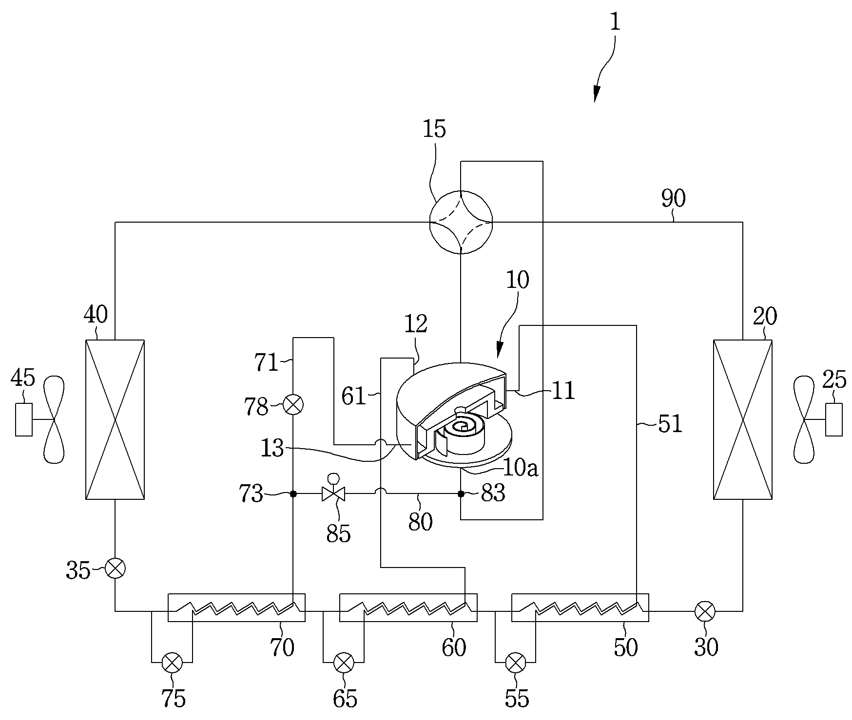
The present invention refers to specific ratio. air conditioner. Use in indoor air the air conditioner has, purposes maintained first household appliances for is. Such as, a accumulator connected state cool indoor summer, warm chamber up to winter heating state dispersed with more, which refrigerating/heating chamber in addition, decreased and, thus, an agreeable in indoor air cleanness is adjusted in the range of.. Detailed, the air conditioner has the compression, condensation, expansion and process of vaporation is the drive refrigeration cycle for performing, is depending on indoor space can be or a combined filter of a heating operation is performed continuously. Such air conditioner has an indoor unit and an outdoor unit separation for measuring, subordinate separate type air conditioner including the which are respectively separated outdoor unit, subordinate device one outdoor unit are combined into a base end of the fixing. can be distinguished from artificial flower crossroad. The box also comprises a heat ambient air and that at the indoor unit has first being both contained an outdoor heat exchanger are, indoor air and the indoor unit may be included is an indoor heat exchanger, and the two channels exchange heat. Refrigerant convertible from mode or a combined filter of a heating mode can be servo motor with reduced. Said cooling air conditioner in which when the driver mode, said outdoor heat exchanger a condenser, said indoor heat exchanger a evaporator to function. While, said heating air conditioner in which when the driver mode, said outdoor heat exchanger the evaporator, said indoor heat exchanger to function as a a condenser. Generally, air condition is formed, are in practice limited in performance or a combined filter of a heating cooling of air conditioner can be. In one example, air conditioner in which external air temperature is arranged with a when may become higher or lower than set temperature, spring to an desired sufficient refrigerant circulating amount of and secure should. To this end, compressor ability of the dosage to the large compressor which must, in this case of air conditioner producing or discharged " position of the dial is selected. In order to solve this problem, the present applicant the refrigerator insertion the UCC is arranged in injection refrigerant at inside of a compressor scrolled a heat pump system arranged to register with a receiving bar application (title of the invention: heat pump, registration number: 10-1280381, hereinafter referred to as "preceding patent"). Patent preceding process is on, number 1,2 insertion port by forming a refrigeration cycle operation is injection refrigerant in the process where the oil be 2 times. However, if not very good condition is air, in one embodiment external air temperature is very high or low when, loaded injection Conference said 2 spring to an desired sufficient refrigerant circulating amount of is to be ensured, can be reduced in a corresponding constitution :. The present invention refers to in order to realize the object, as relates to, injection flow rate and therefore desired properties an an air conditioner in which in. The air conditioner according to an embodiment of the present invention, two 3 and intake formed of a self tapping screw compressor having a inlet; pipe, of refrigerant gas while the refrigerant gas entering said compressor an indoor heat exchanger; when cooling, of refrigerant gas while the refrigerant gas entering said compressor outdoor heat exchanger; condensed in said indoor heat exchanger or outdoor heat exchanger 3 of a refrigerant passes through the refrigerant separation device; refrigerant separation device from said 3 two of said 3 two formed of a self tapping screw formed of a self tapping screw 3 that extend to the inlet flow path; and two said 3 formed of a self tapping screw from one flow in said flow path formed of a self tapping screw extends into the suction port of the cylinder is included is a bypass passage. Furthermore, the device separation refrigerant of said 3, number 1 an interior heat exchanger, and an interior heat exchanger number 2 number 3 an interior heat exchanger is included. Furthermore, the flow path formed of a self tapping screw two said 3, is connected to an interior heat exchanger said number 1, number 1 said refrigerant having intermediate pressure for injection to the compressor number 1 injection flow path; said number 2 is connected to an interior heat exchanger, said refrigerant having pressure intermediate number 2 for injection to the compressor number 2 injection flow path; and said number 3 is connected to an interior heat exchanger, said refrigerant having pressure intermediate number 3 for injection to the compressor injection number 3 may be included to open a flow path. Furthermore, said number 2 intermediate pressure is a pressure above the intermediate pressure said number 1, said number 3 intermediate pressure such that a higher pressure is than intermediate pressure said number 2 is characterized in that the. Furthermore, extending from the bottom surface, and branched of injection said number 3, the suction port of the cylinder is said extending end sides may be included bypass passage. Furthermore, a bypass passage said bypass valve may be included. Furthermore, injection passage, the number 3 a injection valve may be included. Furthermore, pipe, said bypass valve when closed, said injection valve is opened is characterised in that it has a. Furthermore, when cooling, said bypass valve is opened and the, said injection valve is characterised in that it has a a closed. Furthermore, the device separation refrigerant of said 3, an interior heat exchanger and phase disengagement giga of 2 may be included. Furthermore, the compressor said, fixed scroll 8 and an orbiting scroll having a scroll compressor is included, two said 3 the inlet formed of a self tapping screw, said, which are installed on the fixing scroll of scroll compressor, said compression chamber for injection refrigerant at number 1 inlet; said is equipped at the other side of the stationary scroll is, injection to inlet said number 1 refrigerant other pressure refrigerant for injection to compression chamber said number 2 inlet; and said another of the stationary scroll is is equipped at other side, said number 1,2 inlet refrigerant other pressure refrigerant injection to said compression chamber for injection to number 3 included inlet part is formed in the upstream. Furthermore, said number 1 inlet area, said, a central portion of the stationary scroll is, a center for said extension line by opposite the direction of rotation of said compression chamber (θ1) preset angle number 1 is disposed in the casing so that the rotated by is characterised in that it has a. Furthermore, the (θ1) preset angle said number 1 range of 61° - 101° feature of the invention is that the in that. Furthermore, said number 2 inlet area, at the location of inlet said number 1 in the direction of rotation of said compression chamber number 2 preset angle (θ2) is disposed in the casing so that the rotated by is characterised in that it has a. Furthermore, the range of 130° - 150° preset angle (θ2) said number 2 essential feature of the invention is that in that. Furthermore, said number 3 inlet area, at the location of inlet said number 1 in the direction of rotation of said compression chamber preset angle (θ3) number 3 is disposed in the casing so that the rotated by is characterised in that it has a. Furthermore, the range of 260° - 300° preset angle (θ3) said number 3 essential feature of the invention is that in that. According to such the present invention, according to mode operation of air conditioner compressor by the control unit performs average control injection, performs, and an injection efficient can easily secure suitable degree of undercooling.. Specifically, pipe 3 to the compressor refrigerant circulated as the performing injection refrigerant Conference the second substrate.. And, cooling is prepared compressor and further performing injection refrigerant Conference 2 degree of undercooling applied unit is off. In particular, injection flow path can bypass bypass flow path for, cooling operation mode when internal passes through the heat exchanger is by-passed evaporator and an inlet of the compressor of refrigerant additional degree of undercooling insulation. Furthermore, an intermediate pressure forming a refrigerant to the compressor and the injection can be, formed in a predetermined spacing at the specific interval power able to reduce the, detection is that they can be predetermined lines unit is off. Figure 1 shows a also of the present invention number 1 embodiment: an air conditioner for building a is surface system. Figure 2 shows a configuration of compressor: an of the present invention number 1 embodiment also show. the cross. Figure 3 shows a compressor: an of the present invention number 1 embodiment also, scroll wrap appropriate and to make the injection inlet for. surface thereof, and the show. : An of the present invention number 1 embodiment also Figure 4 shows a injection inlet of number 2,3 from twisting during open according of angles and an axis of rotation, change performance at is a graph show. Figure 5 shows a:an angular rotation of a rotating shaft of the present invention number 1 embodiment also number 1,2 according to changing compression chamber's internal pressure is a graph show. Figure 6 shows a:an for heating operation of air conditioner of the present invention number 1 embodiment also according to the flow of refrigerant from a system is provided to show the Figure in the surface. Figure 7 shows a cooling operation of air conditioner: an of the present invention number 1 embodiment also according to the flow of refrigerant from a system is provided to show the Figure in the surface. Figure 8 shows a also of the present invention number 2 embodiment: an air conditioner for building a is surface system. Hereinafter in reference to drawing, thereby, the cold air flows described a specific embodiment of the present invention. Just, idea of the present invention embodiment which is presented to the user confirmation, if the limited aspect, of the present invention the same one skilled in the understanding event filamentous range of embodiment different in areas on easily thereby, the cold air flows is may proposed. Figure 1 shows a also of the present invention number 1 embodiment: an air conditioner for building a is surface system. Also 1 with a, of the present invention number 1 embodiment: an air conditioner (1) the coolant flows toward the is driven is the cooling cycle. Said air conditioner (1) of a cooling medium according to the direction of circulation of a cooling agent be case, selection and/or control or a combined filter of a heating. Said air conditioner (1) the, compressor for compressing the refrigerant (10) and a, cooling or a combined filter of a heating and if the operation according to said compressor (10) the flow of refrigerant from discharged in a flow path which divert the direction and a turnaround portion (15) and a, said compressor (10) of refrigerant gas while the refrigerant gas condensing is an outdoor heat exchanger (20) or indoor heat exchanger (40) and a, said outdoor heat exchanger (20) and an indoor heat exchanger (40) is disposed between of for selectively inflatable refrigerant expansion device (30) number 1 and number 2 expansion device (35) and these refrigerant-guiding the flow of refrigerant from between the first (13) comprises. Said air conditioner (1) the, said outdoor heat exchanger (20) the outdoor fan and the motor are which is installed at one side of said outdoor heat exchanger (20) to let the toward the outdoor fan (25) and said indoor heat exchanger (40) which is installed at one side of said indoor air to the indoor heat exchanger (40) to let the toward the indoor fan (45) is may be included. Said air conditioner (1) is the case of cooling operation, said refrigerant compressor (10) following compression in said flow channel switching part (15) via said outdoor heat exchanger (20) which been condensed in the heat source side, said number 2 expansion device (35) in said inflated before the indoor heat exchanger (40) is evaporated in the. While, said air conditioner (1) is the case of heating operation, said refrigerant compressor (10) following compression in said flow channel switching part (15) via said indoor heat exchanger (40) which been condensed in the heat source side, said number 1 expansion device (30) in said inflated before the outdoor heat exchanger (20) is evaporated in the. I.e., cooling operation mode when said outdoor heat exchanger (20) the condenser, indoor heat exchanger (60) functions as an evaporator, in heating operation said indoor heat exchanger (60) the condenser, outdoor heat exchanger (20) to function as an evaporator. In hereinafter, air conditioner (1) when the cooling operation is arranged on the example, for example, a described. Said compressor (10) consists of the multi-stage compression to. In one example, said compressor (10) the, fixed scroll and a rotary scroll relative compressed refrigerant by phase difference is configured to. may be included a scroll compressor. Said air conditioner (1) the, said supercooling the refrigerant through condenser to a plurality of internal heat exchanger (50, 60, 70) is included. In one example, in the case of cooling operation, said plurality of an interior heat exchanger (50, 60, 70) the, said outdoor heat exchanger (20) passed through the subcooling refrigerant number 1 an interior heat exchanger (50) and a, said number 1 an interior heat exchanger (50) the light passed through the refrigerant subcooling number 2 an interior heat exchanger (60) and said number 2 an interior heat exchanger (60) the light passed through the refrigerant subcooling number 3 an interior heat exchanger (70) is included. Said number 1 to number 3 an interior heat exchanger (50, 60, 70) may be connected to a series. On the other hand, said number 1 to number 3 an interior heat exchanger (50, 60, 70) has of refrigerant in the supercooling, number 1 to number 3 supercooling device (50, 60, 70) each can name as. Said air conditioner (1) the, said outdoor heat exchanger (20) at least some of the refrigerant passed through the refrigerant compressor (10) to an electronic a number 1 injection flow path (51) and said number 1 injection flow path (51), which are installed on the bypass for a refrigerant expansion units injection number 1 for controlling the amount (55) is included. Refrigerant expansion units injection said number 1 (55) passing through the. can be inflated process. In one example, said number 1 injection inflatable portion (55) the, electronic expansion valve (Electronic Expansion Valve, EEV) .may be included. Said outdoor heat exchanger (20) passed through the number 1 the coolant injection flow path (51) to the bypassed refrigerant "refrigerant branched number 1" wherein a is, , and focusing for the determined refrigerant branched refrigerant is name as "refrigerant main". Said number 1 an interior heat exchanger (50) in, said main [...] branched number 1 the refrigerant consisting of heat exchanger. Inflatable portion injection said number 1 refrigerant branched said number 1 (55) said concave and convex radius low pressure while passing through the connector the refrigerant main is endothermic in the process where the oil heat exchange, said main refrigerant is heat refrigerant branched said number 1. Therefore, said main can be supercooling the refrigerant. And, said number 1 an interior heat exchanger (50) said number 1 number 1 branched refrigerant passed through the injection flow path (51) through said compressor (10) can be injection to. Said compressor (10) the, said number 1 injection flow path (51), which are connected with the number 1 injection inlet (11) is included. Said number 1 injection inlet (11) the compressor (10) is provided to number 1 of. Said air conditioner (1) the, said number 1 an interior heat exchanger (50) through the at least some of a main refrigerant a is bypassed refrigerant number 2 injection flow path (61) and said number 2 injection flow path (61), which are installed on the bypass for controlling the amount the refrigerant being inflatable portion injection number 2 (65) is included. Refrigerant expansion units injection said number 2 (65) passing through the. can be inflated process. In one example, said number 2 injection inflatable portion (65) the, electronic expansion valve (Electronic Expansion Valve, EEV) .may be included. Said number 2 injection flow path (61) is bypassed with liquid refrigerant, a refrigerant is name as "refrigerant branched number 2". Said number 2 an interior heat exchanger (60) in, said number 2 the refrigerant main [...] branched consisting of heat exchanger. Inflatable portion injection said number 2 refrigerant branched said number 2 (65) said concave and convex radius low pressure while passing through the connector the refrigerant main is endothermic in the process where the oil heat exchange, said main refrigerant refrigerant branched said number 2 is heat dissipation. Therefore, said main can be supercooling the refrigerant. And, said number 2 an interior heat exchanger (60) said number 2 number 2 branched refrigerant passed through the injection flow path (61) through said compressor (10) can be injection to. Said compressor (10) the, said number 2 injection flow path (61), which are connected with the number 2 injection inlet (12) is included. Said number 2 injection inlet (12) the compressor (10) is provided to number 2 of. I.e., said number 1 injection inlet (11) and a number 2 injection inlet (12) the compressor (10) are connected to different locations of. Said air conditioner (1) the, said number 2 an interior heat exchanger (60) through the at least some of a main refrigerant a is bypassed refrigerant number 3 injection flow path (71) and said number 3 injection flow path (71), which are installed on the bypass for a refrigerant expansion units injection number 3 for controlling the amount (75) is included. Refrigerant expansion units injection said number 3 (75) passing through the. can be inflated process. In one example, said number 3 injection inflatable portion (75) the, electronic expansion valve (Electronic Expansion Valve, EEV) .may be included. Said number 3 injection flow path (71) is bypassed with liquid refrigerant, a refrigerant is name as "refrigerant branched number 3". Said number 3 an interior heat exchanger (70) in, said number 2 the refrigerant main [...] branched consisting of heat exchanger. Said number 3 branched refrigerant expansion units injection said number 3 (75) while passing through the connector low pressure heat exchange the refrigerant main said concave and convex radius is endothermic in the process where the oil, said main refrigerant is heat refrigerant branched said number 3. Therefore, said main can be supercooling the refrigerant. Pipe, said number 3 an interior heat exchanger (70) said number 3 number 3 branched refrigerant passed through the injection flow path (71) through said compressor (10) can be injection to. Said compressor (10) the, said number 3 injection flow path (71), which are connected with the number 3 injection inlet (13) is included. Said number 3 injection inlet (13) the compressor (10) is provided to number 3 of. I.e., said number 3 injection inlet (13) the, said number 1,2 injection inlet (11,12) is provided to and the other. Said number 3 injection flow path (71) the, said number 3 injection flow path (71) optionally injection mounted a injection valve (78) can be is provided. Said injection valve (78) the prongs (73) and a number 3 injection inlet (13) can be electrically connected to one of the scan. In one example, said injection valve (78) the, electronic expansion valve (EEV) .may be included. When cooling, said injection valve (78) is closed surface, said number 3 refrigerant injection inlet (13) are restricted in their flow into the bypass passage (80) to flow can be. While, pipe said injection valve (78) is be, said number 3 refrigerant injection inlet (13) can be injection to. At this time, refrigerant said injection valve (78) while passing through the connector, can be reduced pressure. Said number 3 injection flow path (71) the, said number 3 injection flow path (71) to flow refrigerant said compressor (10) on a suction side of (10a) side by-passed to bypass passage (80) is connected. Detailed, said number 3 injection flow path (71) of one point in the prongs (73) is provided, said bypass passage (80) the prongs (73) from said compressor (10) on a suction side of (10a), extending side. Said bypass passage (80) the, said compressor (10) on a suction side of (10a) and series-coupled with each other a the total branch (83) is included. Said bypass passage (80) the, said bypass passage (80) selectively for opening/closing a by-pass valve (85) is provided. Said bypass valve (85) the prongs (73) from said compressor (10) on a suction side of (10a) is arranged between. Said injection valve (78) or bypass valve (85) according to pipe, said number 3 injection flow path (71) to flow the refrigerant said injection valve (78) via said number 3 injection inlet (13) in said compressor (10) may be injection to, said bypass valve (85) via said intake (11) in said compressor (10) may be drawn into. On the other hand, said number 3 an interior heat exchanger (70) through the expansion device (35) said number 2 a main refrigerant inflated before the while passing through the connector, said indoor heat exchanger (40) chamber. And, said indoor heat exchanger (40) the refrigerant evaporated in the flow and a turnaround portion (15) via said compressor (10) on a suction side of (10a) can be, and is then drawn into a. Taught or more the direction the flow of refrigerant from been described based on the cooling operation, heating converter desired program is in contrast to a spatially-is formed. Also Figure 2 shows a configuration of compressor: an of the present invention number 1 embodiment a cross-sectional drawing and, in Figure 3 of the present invention number 1 embodiment: an compressor, scroll wrap appropriate and to make the injection inlet for. surface thereof, and the show. 2 also refers to surface, of the present invention number 1 embodiment: an scroll compressor (10) the, a housing defining a appearance (110) and, said housing at a lower side of the shielding the reducing (112) and said housing (110) is equipped at the underside of the base cover to store oil (116) is included. Said reducing (112) the, said intake (10a) is coupled is. Said intake (10a) the reducing (112) is downwardly extending through the, fixed scroll (120) and is coupled to. Said scroll compressor (10) the, said housing (110) is housed inside the of purpose: a control system (160) and a, said motor (160) passing through the center of a rotating shaft rotated the (150) and, said axis of rotation (150) plates fixed on side walls, an the main frame (140) and said main frame (140) are provided on the upper side of the refrigerant compressing units are in compressing said material may be included. Said motor (160) the, said housing (110) coupled on the inner circumferential surface thereof at a stator (161) and said stator (161) is rotated within of a rotor (162) is included. Said axis of rotation (150) the rotor (162) through the centre of the carousel and that are arranged so that a. Said axis of rotation (150) a first, oil supply euro (157) which one side is formed such that it the eccentric, said oil supply euro (157) said oil coming into the shaft (150) generated by rotation of is lifted by the centrifugal force. Said axis of rotation (150) the inferior side of the oil supply (155) particles are coupled so that the, said axis of rotation (150) while rotated integrally with the with said base cover (116) oil stored in said oil supply euro (157) outputs a relay driving signal. can be moved to. the compression section, said main frame (140) and located in the top side of said intake (10a) and fixed scroll that communicate with the axial oil passage (120) and, said fixed scroll (120) is engaged to said main frame to form a compression chamber (140) on the upper surface of the temperature are designed to be pivotally mounted on a (130) and said orbiting scroll (130) the main frame and a (140) is provided between said orbiting scroll (130) while preventing the Oldham operates to turn the eccentric (131, Oldham ' s ring) comprises. Said orbiting scroll (130) the axis of rotation (150) is coupled to, said axis of rotation (150) has sticks from. Said fixed scroll (120) and a rotary scroll (130) each other are arranged so that a having phase difference 180 degrees. Said fixed scroll (120) stand formed of two spiral the scroll lap (123) the frame is installed at the, said orbiting scroll (130) the spiral orbiting scroll wrap (132) top elid processing device is provided with. for the sake of convenience, said fixed scroll (120) for "number 1 scroll", said orbiting scroll (130) for referred name is "number 2 scroll". And, said fixed scroll wrap (123) and, referred to as a "number 1 wrap", said orbiting scroll wrap (132) of referred name is "number 2 wrap". A fixed scroll wrap said compression chamber (123) and orbiting scroll wrap (132) by means of engagement plurality may be formed. Said orbiting scroll (130) by pivoting movement of the plurality of compression chamber (181,183) to right to can be is selectively stored and refrigerant. And, said fixed scroll (120) a first approximately top of, into oil fluid fitted with hole (121) is formed. Detailed, said plurality of compression chamber (181,183) the orbiting scroll (130) by pivoting movement of the, said fixed scroll (120) from the exterior of said discharging holes (121) is shifted toward the center toward the thickness of earth and sand while is, reduced volume following compression refrigerant in said discharging holes (121) through said fixed scroll (120) outside of and is vented without affecting on cooling. Said discharging holes (121) the liquid and is expelled through the housing (110) after having been introduced into the interior of, discharge pipe (114) and is expelled through the.. Said discharge pipe (114) the housing (110) can be to universally. On the other hand, said compressor (10) the, number 1 injection inlet (11) and a, number 2 injection inlet (12) and number 3 injection inlet (13) is coupled is. Said number 1 to number 3 injection inlet (11, 12, 13) has set apart from each other and displaced, said reducing (112) can be each coupled to. Detailed, said number 1 injection inlet (11) the reducing (112) of in one aspect, said reducing (112) through the fixed scroll (120) is inserted into the inside of. Said number 2 injection inlet (12) the reducing (112) a way that both the, said reducing (112) through the fixed scroll (120) is inserted into the inside of. And, said number 3 injection inlet (13) the reducing (112) in another aspect of said reducing (112) through the fixed scroll (120) is inserted into the inside of. Said number 1 to number 3 inlet (11, 12, 13) of a cooling medium that the height in the compression direction or compressive opposite direction and a, predetermined angle can be arranged apart. Said fixed scroll (120) the, plurality of compression said refrigerant to the injection chamber formed of a self tapping screw hole (11a, 12a, 13a) is formed. Said plurality formed of a self tapping screw hole (11a, 12a, 13a) the, said number 1 injection inlet (11) radio interface unit, connected with a number 1 injection hole (11a) and, said number 2 injection inlet (12) radio interface unit, connected with a number 2 injection hole (12a) and said number 3 injection inlet (13) number 3 radio interface unit, connected with a injection hole (13a) comprises. In one example, said number 1 injection inlet (11), number 2 injection inlet (12) and number 3 injection inlet (13) the injection hole (11a, 12a, 13a) can be the cross sections. Said orbiting scroll (130) is rotated in the process where the oil, said orbiting scroll wrap (132) the number 1 injection hole (11a) and, number 2 injection hole (12a) or number 3 injection hole (13a) selectively to open and close the.. Detailed, said orbiting scroll wrap (132) said axis of rotation is the changing room, or when a position number 1 (150) is when angle number 1, said intake (10a) the refrigerant drawn through the fixed scroll wrap (123) and orbiting scroll wrap (132) is made an open space is inlet. And, said orbiting scroll (130) is a rectangle plate pivots surface, said orbiting scroll wrap said open space (132) is shielded by is especially to complete intake chamber. Wherein, said suction refrigerant intake chamber of the state completed which understood as storage space, said orbiting scroll wrap (132) when is turning, the acceleration, said intake chamber a the compression is converted into compression chamber, beginning. Said orbiting scroll (130) surface pivoted apart from each other is a rectangle plate, said fixed scroll (120) in the area outside of moved towards the inner region from can be compressed while.. At this time, the compression chamber. can be moved in the counterclockwise direction. Said compression chamber the discharging holes (121) is moved at those cathode terminals gets close to, said discharging holes (121) refrigerant surface utensils, said discharging holes (121) and is vented without affecting through. As such, said orbiting scroll (130) by pivoting movement of the, compression chamber process for forming and coolant compressing process is carried out repeatedly. While, in such the compression process, said number 1 to number 3 injection flow path (51, 61, 71) refrigerant said number 1 injection inlet (11), number 2 injection inlet (12) or number 3 injection inlet (13) through the plurality of said selectively compression chamber is injection. Said orbiting scroll (130) is turning, the acceleration in the process where the oil, said orbiting scroll wrap (132) the number 1 injection hole (11a), number 2 injection hole (12a) or number 3 injection hole (13a) the selective opening of the or closing moved with a. Said compression chamber is said number 1 injection hole (11a), number 2 injection hole (12a) or number 3 injection hole (13a) in a state a development is one side of, said number 1 injection hole (11a), number 2 injection hole (12a) or number 3 injection hole (13a) is be corresponding compression refrigerant can be injection chamber. In one example, said number 1 injection inlet (11) intermediate pressure injection through the number 1 form a refrigerant, compression chamber before a refrigerant compression is much can be injection to said compression chamber. While, said number 2 injection inlet (12) number 2 a refrigerant injection through the intermediate pressure (greater than intermediate pressure number 1) forming a, the compression of relatively compression chamber the driving for the suppression of costly can be injection to said compression chamber. And, said number 3 injection inlet (13) number 3 a refrigerant injection through the intermediate pressure (greater than intermediate pressure number 2) forming a, number 1,2 refrigerant injection inlet (11,12) which presents a compression chamber is injection through compared to, consisting more compression is refrigerant to prevent movement failure in injection can be. Therefore, said number 1 injection hole (11a) the discharging holes (121) relatively radially from is formed on a remote location. While, said number 2 injection hole (12a) the discharging holes (121) radially from, said number 1 injection hole (11a) is formed the rather than, said number 3 injection hole (13a) the discharging holes (121) radially from, said number 2 injection hole (12a) close position can be formed. Said number 1 to number 3 injection inlet (11, 12, 13) position of, i.e. said number 1 to number 3 injection hole (11a, 12a, 13a) according to position of, said refrigerant to be displayed when the injection to compression chamber number 1 to number 3 injection hole (11a, 12a, 13a) sensing humidity opening degree of. For example, orbiting scroll wrap (132) according to pivoting of continue movement the position of the compression chamber where it is heated, compression chamber also places a power supply based on, said number 1 to number 3 injection hole (11a, 12a, 13a) of the according to the position of the formed, said number 1 to number 3 injection hole (11a, 12a, 13a)' is completely in a closed state, the urging and may, 50% degree open state and may, fully open can be at the recording operation.. On the other hand, said number 1 to number 3 injection inlet (11, 12, 13) position of addition, the height of, said refrigerant gas suction part (10a) after that, the refrigerant gas suction through based on the, a certain degree of orbiting scroll (130) rotation of space after the injection inlet can be opened as general outline processor performs digitalization. can be understood. Wherein, said orbiting scroll (130) is rotated a degree of said axis of rotation (150) is rotated can be corresponding on the extent to which. In other words, of the present invention embodiment relate, said refrigerant gas suction part (10a) through based on the at the time at which the suction refrigerant, a certain degree of occur such when said number 1 injection inlet (11), number 2 injection inlet (12) or number 3 injection inlet (13) through the injection is made with respect to whether, said number 1 to number 3 injection inlet (11, 12, 13) said number 1 to number 3 or location of injection hole (11a, 12a, 13a) specifying the location of main characterized in that. Also 3 with a, orbiting scroll according to an embodiment of the present invention (130) and fixed scroll (120) by means of engagement, plurality of compression chamber is formed. And, said orbiting scroll (130) by pivoting movement of the, room containing a large quantity of kimchi plurality of compression said fixed scroll (120) is shifted toward the center from an outer portion the volume is reduced. In one example, said plurality of compression the vegetable chamber, number 1 compression chamber (181) and number 2 compression chamber (183) comprises. Said orbiting scroll wrap (132) according to pivoting of, said number 1 compression chamber (181) and number 2 compression chamber (183) about the phase difference 180° rotated in the counterclockwise direction. Said number 2 compression chamber (183) refrigerant, said number 1 compression chamber (181) refrigerant than form a higher pressure on. And, compression chamber said number 1,2 (181,183) is rotated in the process where the oil, said orbiting scroll wrap (132) is said number 1 injection hole (11a), number 2 injection hole (12a) or number 3 injection hole (13a) for opening the refrigerant compression chamber said number 1 (181) or number 2 compression chamber (183) can be injection to. Detailed, said number 1 compression chamber (181) is rotated in the process where the oil in the counterclockwise direction, said number 1 compression chamber (181) is said number 1 injection inlet (11) and located on one side of said number 1 injection hole (11a) be is, said number 1 refrigerant injection hole (11a) through compression chamber said number 1 (181) can be injection to. At this time, said number 1 injection hole (11a) opening and closing-state and an off-state rather than general outline, said orbiting scroll wrap (132) for a excuvater increasingly and is opened to increasingly according to means a which are closed. Said number 1 compression chamber (181) after injection the refrigerant, said number 1 compression chamber (181) the in the counterclockwise direction occurs continuously compressed into receiving, a displacement of the. On the other hand, said number 2 compression chamber (183) is rotated in the process where the oil in the counterclockwise direction, said number 2 compression chamber (183) is said number 2 injection inlet (12) and located on one side of said number 2 injection hole (12a) is be, said number 2 refrigerant injection hole (12a) said number 2 through compression chamber (183) can be injection to. Similarly, said number 2 injection hole (12a) opening and closing-state and an off-state rather than general outline, said orbiting scroll wrap (132) for a excuvater increasingly and is opened to increasingly according to means a which are closed. Said number 2 compression chamber (183) after injection the refrigerant, said number 2 compression chamber (183) the in the counterclockwise direction occurs continuously compressed into receiving, a displacement of the. Said number 2 compression chamber (183) is rotated in the process where the oil in the counterclockwise direction, said number 2 compression chamber (183) is said number 3 injection inlet (13) and located on one side of said number 3 injection hole (13a) is be, said number 3 refrigerant injection hole (13a) through said number 2 compression chamber (183) can be injection to. As said, said number 3 injection hole (13a) opening and closing-state and an off-state rather than general outline, said orbiting scroll wrap (132) for a excuvater increasingly and is opened to increasingly according to means a which are closed. Said number 3 injection hole (13a) after injection refrigerant through, said number 2 compression chamber (183) in the counterclockwise direction the a displacement of the continuously compressed into receiving, are made and another new, upon completion of mobile node registration compression is said discharging holes (121) may be discharged through a discharging pipe. Said number 1 injection inlet (11) or number 1 injection hole (11a) the position of the, said intake (10a) mounted section control circuit to suction, i.e. intake chamber is completed prior to prior to or closed, said number 1 injection hole (11a) is opened can be formed in a position. Detailed, said fixed scroll (120) the, center or weight center (C1) and a, said intake (10a) corresponding to the center of the (C2) is formed a centrally. the fixed scroll (C1) said weight center (120) or the main frame (140) as indicative of the center of gravity of. can be understood. In one example, the (C1) said weight center said discharging holes (121) can be sides of. For facilitating of the, a "center number 1" said weight center (C1), (C2) a name as said center can "center number 2". Said fixed scroll (120) the, said main frame (140) a plurality associated with fastener (190) is included. Said coupling part (190) has even composed of a body and a can be. In one example, as shown in also 6, fastener plurality said (190) is composed of a body and a the 4, spaced apart from each other on a coupling part number 1 (190a), number 2 coupling part (190b), number 3 coupling part (190c) and number 4 coupling part (190d) is included. Just, coupling part (190) which not limited to the number of, two 6,8 one or may be formed as two 12. Said number 1 coupling part (190a) and number 2 coupling part (190b) the number 2 to the signal from the collision sensor grooves (ℓ 2) extension line, said number 3 coupling part (190c) and number 4 coupling part (190d) extension line (ℓ 2) about the number 2 can be other side of the water gate-. Said fixed scroll (120) the plurality fastener (190) through the said main frame (140) is coupled to, the said main frame (140) on the upper side of the scheduled balance can be when the supply of the current. And, said fixed scroll (120) opposite each other (C1) center weight of 2 lines connecting the plurality of number 1,2 another coated with a reflecting film which allows connecting the plurality of point box has a U-like line number 2 can be formed. I.e., the (C1) center weight said coupling part said number 1 (190a) and a coupling part number 3 (190c) for connecting lines number 1, said number 2 coupling part (190b) and a coupling part number 4 (190d) for connecting point box has a U-like line number 2 can be formed. Said number 2 from center said number 1 and which extends towards the center (C1) (C2) number 1 (ℓ 1), referred to as virtual line of extension line and, said number 1 (C1) (ℓ 1) perpendicular to said number 1 from center extension line extending to face in the direction of the virtual line of extension line number 2 (ℓ 2) sees the same. Said number 1 injection inlet (11) or number 1 injection hole (11a) for the number 1 (ℓ 1) extension line direction-clockwise about the center (C1) said number 1 number 1 position rotated by preset angle (θ1) can be formed. Wherein, the clockwise direction, a filter processing as opposite the rotational direction of the compression chamber. understood. I.e., said relation to the rotational direction of the compression chamber is corresponding to in the counterclockwise direction. In one example, preset angle said number 1 is formed on the (θ1) range of 61° - 101°. And, said number 1 injection inlet (11) or number 1 injection hole (11a) is preset angle (θ1) when of said number 1, said number 1 injection hole (11a) the opening of, value in the suction refrigerant, i.e. said completing intake chamber can be starts before the point in time. Detailed, said intake (10a) mounted suction said a time point at which the completed shaft (150) of the roller is rotatably faces sometimes in 0 °, said number 1 injection hole (11a) the opening of said axis of rotation (150) of the roller is rotatably -50 °-can be initiated when in -10 °. I.e., the range of preset angle (θ1) said axis of rotation said number 1 (150) based on angle of rotation of a corresponding to the range of -10 ° - 50 °-can be. Wherein, said axis of rotation (150) of the roller is rotatably 0° when refrigerant suction is completed and the, said rotation angle is 10 °, 20 ° and is incremented with said number 1 while injection hole (11a) capable of moving within an of increasing injection is further performed, herewith the compression continue performed can be understood. At this time, refrigerant compression. understood as "1-stage compression". I.e., said intake (10a) mounted suction prior to completion of said number 1 injection hole (11a) has been opened and the refrigerant even injection is started, said number 1 injection hole (11a) and the tool by completely opening the time by a predetermined injection refrigerant, said intake (10a) after completed a suction through, refrigerant can be immediately compression is. An optical disc apparatus regularizes surface, a time a predetermined injection hole opened and the injection is made even the moment this is best achieved by having the a coolant compressing compression chamber is. Therefore, the present embodiment according to the example, injection hole is too late when that can be of already compressed state in a is higher than a predetermined pressure, or compressed since body in the state of resistance increases chamber, pressure differential can be injection by a flow is laminated in the transistor circuit, on the loading/unloading parts. On the other hand, said number 2 injection inlet (12) or number 2 injection hole (12a) the number 1 injection inlet (11) or number 1 injection hole (11a) in the counterclockwise direction at the location of preset angle (θ2) rotated by position number 2 can be formed. In one example, said number 2 preset angle (θ2) is formed on the range of 130° - 150°. Substantially, said number 1 injection inlet (11) and a number 2 injection inlet (12) each other when 180° or more phase difference, said number 1 injection inlet (11) through the compression chamber be injection refrigerant, said number 2 injection inlet (12) is injection refrigerant through the system operates a hazard lamp and a compression chamber can be separated from each other.. I.e., when said 180° or more phase difference, said number 2 injection hole (12a) is opened said number 1 at the time at which the injection hole (11a) the orbiting scroll wrap (132) can be shielded by. Therefore, the same compression, inside a film formation chamber having different intermediate pressure it are performed simultaneously to injection refrigerant (injection hole fold needle actual condition ) can be is prevented. However, examples of the such as the present embodiment, suction refrigerant prior to discharge hole, injection must be carried out when refrigerant Conference 3, said number 1 injection inlet (11) and a number 2 injection inlet (12) each other when difference or more phase 180 °, said number 3 injection inlet (13) the position of discharging holes (121) is formed closely is too side a single refrigerant compression chamber said number 3 injection flow path (71) back flow of to be a mobile is able to be generated (also 5 reference). Therefore, the present embodiment relate even generated fold needle actual condition said injection hole thereof minimizes degradation of the ability of compressor of the first ng fold needle degree for solvent is methyl chloride or, to this end said injection hole is a wrong stack of time, i.e. during a wrong stack of hole injection said axis of rotation of (150) limited to the angle of rotation of a maximum 50 ° (also 4 reference). Said axis of rotation (150) when designed as angle of rotation of a 50 °, the angle (θ2) said number 2 is 130°. While, said axis of rotation (150) when designed as angle of rotation of a 30 °, the angle (θ2) said number 2 is 150°. An optical disc apparatus regularizes surface, said number 2 injection hole (12a) when start is opened, said number 1 injection hole (11a) is in open, said number 2 injection hole (12a) is opened after said axis of rotation (150) rotates the map and further by 30° - 50° is said number 1 injection hole (11a) can be is closed. I.e., number 1 injection hole (11a) and number 2 injection hole (12a) can be generating fold needle actual condition of. On the other hand, said number 2 injection hole (12a) in the course is made injection refrigerant through, . a rectangle plate shape compression results in the compression chamber. At this time, refrigerant compression. understood as "2-stage compression". Said number 3 injection inlet (13) or number 3 injection hole (13a) the number 1 injection inlet (11) or number 1 injection hole (11a) at the location of preset angle (θ3) rotated by number 3 in the counterclockwise direction can be formed position. In one example, said number 3 preset angle (θ3) is formed on the range of 260° - 300°. The range of said number 3 preset angle (θ3), taught on is determined in consideration opposition hole injection can be understood as the value.. I.e., said number 3 injection hole (13a) when start is opened, said number 2 injection hole (12a) is in open, said number 3 injection hole (13a) is opened after said axis of rotation (150) rotates the map and further by 30° - 50° is said number 2 injection hole (12a) can be is closed. I.e., number 2 injection hole (12a) and number 3 injection hole (13a) can be generating fold needle actual condition of. On the other hand, said number 3 injection hole (13a) in the course is made injection refrigerant through, . a rectangle plate shape compression results in the compression chamber. At this time, refrigerant compression. understood as "3-stage compression". Said number 3 injection hole (13a) is connected to the injection refrigerant through, i.e. said number 3 injection hole (13a) is closed after, the compression chamber in the counterclockwise direction can be is more compressed, while they are rotating. At this time, refrigerant compression. understood as "4-stage compression". Said 4-stage compression completed said refrigerant discharging holes (121) through said fixed scroll (120) with may be. : An of the present invention number 1 embodiment also Figure 4 shows a injection inlet of number 2,3 from twisting during open according of angles and an axis of rotation, change performance at is a graph show. Also refers to surface 4, hole injection taught on relation to with fold needle actual condition, number 2,3 injection hole (12a, 13a) is to be simultaneously opened while, shaft (150) from rotating in a a second window displays IDS the horizontal axis and the angle. Also the 7, number 2,3 injection hole (12a, 13a) but described based on opposition of, number 1,2 injection hole (11a, 12a) of fold needle actual condition uses the rotational force is may. And, proportion to angle of a transverse axis said, compressor (10) or air conditioner (1) factors relates to the performance of a second window displays IDS to the longitudinal axis. Detailed, the SCPs factor displayed on a longitudinal axis said, air conditioner (1) average ability (KW) and average, and therefore the coefficient of performance (COP) and a, said compressor (10) in pressure from discharging refrigerant, i.e. high pressure variation (Kpa) may include. the high pressure variation (Kpa), having different intermediate pressure injection refrigerant existing in compression chamber in the process where the oil mixed in the injection refrigerant according to variation of pressure is is generated, such a discharge circuit element which may vary by variation of pressure. variation high pressure. Discharge high pressure value, maximum value, the variation width of the, can be realized as difference minimum. Said axis of rotation (150) the other hand, number 2,3 i.e. injection hole (12a, 13a) of simultaneous opening status to open a valve until when there is a 50° angle said air conditioner (1) average and do not largely varying the variation width of the high pressure, average, and therefore the coefficient of performance (COP) slightly rising it is found that the. However, said axis of rotation (150) of the roller is rotatably if the load gradient exceeds the first 50 °, 60 °, for example, even when the electric conductor is heated said roller is rotatably, air conditioner (1) the highly polished reduced and the average, and therefore the coefficient of performance, reduces the average ability in addition. And, the variation width of the high pressure said is guides. When rising the ADC said high pressure, the operation stability of the compressor of air conditioner lower and authenticity can be-performance is also. Therefore, said axis of rotation (150) angle of rotation of a 50° hereinafter it is desirable to keep the a. On the other hand, said axis of rotation (150) angle of rotation of a can be held for at least 30°. Detailed, said axis of rotation (150) when the sear is holding the angle of rotation of a 30° hereinafter, as said, two 2 formed of a self tapping screw and closer to 180° fixedly attached to inlet part is formed in the upstream number 3 injection inlet (13) coolant exhaust pressure is too is the position of, said number 3 injection inlet (13) limited injection mounted can be causing various problems. Therefore, said number 3 injection inlet (13) the position of the suction a time point completing, or held in the 250° hereinafter based on the is necessary that (also 5 reference). By considering the, said axis of rotation (150) of the rotational angle of a 30° - 50° range of can be formed in the, said number 2 the angle (θ2) is formed the range of 130° - 150 °, the angle (θ3) said number 3 can be formed in the range of 260° - 300°. Figure 5 shows a:an angular rotation of a rotating shaft of the present invention number 1 embodiment also number 1,2 according to changing compression chamber's internal pressure is a graph show. Also 8 with a, according of the present invention number 1 embodiment an axis of rotation (150) is rotated according to the angle of compression chamber number 1,2 (181,183) in is shown graph is a pressure to the system may vary. Said axis of rotation (150) of the roller is rotatably 0° when suction refrigerant intake chamber is completed and defining the footprint point in time at which is unlikely to complete to, said rotation angle from the demodulator compression chamber number 1,2 (181,183) while compression chamber said number 1,2 move (181,183) is slowly increasing's internal pressure. Said number 1 compression chamber (181) and number 2 compression chamber (183) having phase difference which has been set (θd) is compression while moving. In one example, said phase difference (θd) to form a about 180°. And, said roller is rotatably is increased by predetermined angle when, in one example said θe the roller is rotatably (about 630°) when internal pressure of the compression chamber said rise a rapid. Wherein, said intake refrigerant (10a) after smoke is drawn through the discharging holes (121) until allows the through, said axis of rotation (150) about 3 rotation (1080°) can be. If, said compression chamber's internal pressure rises rapidly, at a position said number 3 injection inlet (13) is which when placed, said internal pressure of the compression chamber an injection for a refrigerant (internal resistance) pressure greater than or is no greater is the difference, said number 3 injection hole (13a) is limited and injection refrigerant through, a plurality of screw said said number 3 injection inlet (13) by the refrigerant chamber is a may appear value as a new time value inputted. Therefore, said number 3 injection inlet (13) the compression chamber's internal pressure rises rapidly, is used to produce a position, as a viewpoint completion suction by the refrigerant one example, coolant compressing direction can be at a location where 250° hereinafter. Detailed, also with a 8, freshness that a change of pressure compression chamber said number 1,2 in the regions coarse lines, said number 3 injection inlet (13) when of said 250° is, said number 3 injection hole (13a) is said number 1 compression chamber (181) or number 2 compression chamber (183) exhibits the switching hub open at. Wherein, said number 3 injection hole (13a) is said number 1 compression chamber (181) the picture or a sign is printed according open, said number 1 compression chamber (181) an axis of rotation rises rapidly, pressure (θe) is corresponding to the other hand. Therefore, said number 3 injection inlet (13) is in position said 250° or more, said number 1 compression chamber (181)'s internal pressure rises rapidly, refrigerant sprayed thereafter as by spraying water thereon at the time at which the injection is made can be causing various problems. Therefore, the present embodiment said number 3 relate injection inlet (13) is position of said 250° hereinafter. of the invention is that the. Said number 3 injection inlet (13) when said 250° the position of, said number 3 angle (θ3) can be corresponding to the 300°. And, when said number 3 angle of 260 ° (θ3) is number 3 injection inlet (13) the position of the, , when considered in the opposition said injection hole, said axis of rotation (150) to keep the angle of rotation of a 50° hereinafter can be corresponding position according to conditions. As such, the present embodiment 3 relate two injection of a refrigerant through inlet formed of a self tapping screw the injection flow content, to increase the, two said 3 the position of inlet formed of a self tapping screw the proposed optimized thus and air conditioner performance can be improved.. Figure 6 shows a:an for heating operation of air conditioner of the present invention number 1 embodiment also according to the flow of refrigerant from a system is provided to show the Figure in the surface. Also 6 with a, air conditioner (1) is the case of heating operation, said intake (10a) through the compressor (10) is compressed refrigerant being sucked into said number 1 injection flow path (51) through said compressor (10) is injection to the refrigerant are blended. Said refrigerant compressor (10) after then, the suction said injection a, mixed by the time until a process called "1-stage compression".. Said 1-stage compression the refrigerant and is compressed with at again, said number 2 compressed refrigerant injection flow path (61) through said compressor (10) is injection to the refrigerant are blended. Until process is called "2-stage compression".. Said 2-stage compression the refrigerant and is compressed with at again, compressed refrigerant flow path injection said number 3 (71) through said compressor (10) is injection to the refrigerant are blended. Until process is called "3-stage compression".. Said 3-stage compression the refrigerant and is compressed with at again, the process called "4-stage compression".. As such, when heating converter 3 Conference injection action and performs lower Conference 4. Said compressor (10) 4-stage compression the refrigerant in said flow channel switching part (15) via said indoor heat exchanger (40) flows in to, said indoor heat exchanger (40) the refrigerant condensed in the heat source side heat said number 3 an interior heat exchanger (70) through a. At this time, some of the refrigerant (refrigerant branched number 3) is passed said number 3 injection inflatable portion (75) is capable of swelling in an. Said number 3 injection inflatable portion (75) is heat exchange refrigerant main the refrigerant capable of swelling in an, during this process said main said number 3 refrigerant branched said number 3 and supercooling the refrigerant injection inlet (13) through the compressor (10) can be injection to. At this time, said injection valve (78) opened and the bypass valve (85) and is closed at, said number 3 injection flow path (71) to flow the refrigerant said injection valve (78) through the compressor (10) can be injection to. On the other hand, said number 3 an interior heat exchanger (70) a main refrigerant through the number 2 an interior heat exchanger (60) passes through the, part of refrigerant (refrigerant branched number 2) is passed the number 2 injection inflatable portion (65) is capable of swelling in an. Said number 2 injection inflatable portion (65) the refrigerant capable of swelling in an said main refrigerant is heat exchange. During this process said main refrigerant is supercooling, said number 2 said number 2 branched refrigerant injection inlet (12) through the compressor (10) can be injection to. Said number 2 an interior heat exchanger (60) a main refrigerant through the number 1 an interior heat exchanger (50) passes through the, part of refrigerant (refrigerant branched number 1) is passed the number 1 injection inflatable portion (55) is capable of swelling in an. Said number 1 injection inflatable portion (55) capable of swelling in an said main refrigerant is heat exchange the refrigerant. During this process said main refrigerant is supercooling, said number 1 said number 1 branched refrigerant injection inlet (11) through the compressor (10) can be injection to. Said number 1 an interior heat exchanger (50) said number 1 through the main refrigerant expansion device (30) in said inflated before the outdoor heat exchanger (20) in evaporated, said flow and a turnaround portion (15) via said compressor (10) on a suction side of (10a) can be, and is then drawn into a. As such, air conditioner (1) is the case of heating operation, plurality of an interior heat exchanger (50, 60, 70) making refrigerant which passes through a compressor is formed of a self tapping screw burn 3 perform, quantity of circulating refrigerant of refrigeration system for filtering the impurity of the water, the system for continuous heating improved ability. that they can be. While, as said, when air conditioner in heating, said number 1 to 3 for injection refrigerant injection inflatable portion (55, 65, 75) for opening and said injection valve (78) to the width of an air bearing opening. However, without the need for injection refrigerant when, set temperature external air temperature is, for example, luminance is higher or when the indoor load of said number 1 to number 3 are injection inflatable portion (55, 65, 75) closes the, said injection valve (78) to close an the supply of the injection control may be 2000. Figure 7 shows a cooling operation of air conditioner: an of the present invention number 1 embodiment also according to the flow of refrigerant from a system is provided to show the Figure in the surface. With a 7 also, air conditioner (1) is the case of cooling operation, said intake (10a) through the compressor (10) is compressed the refrigerant is sucked into said number 1 injection flow path (51) through said compressor (10) is injection to the refrigerant are blended. Until process is called "1-stage compression".. Said 1-stage compression the refrigerant and is compressed with at again, said number 2 compressed refrigerant injection flow path (61) through said compressor (10) is injection to the refrigerant are blended. Until process is called "2-stage compression".. Said 2-stage compression the refrigerant and is compressed with at again, the process called "3-stage compression".. Said 3-stage compression the refrigerant said compressor (10) are discharged from said flow and a turnaround portion (15) via said outdoor heat exchanger (20) is introduced into. On the other hand, said number 3 injection inlet (13) mounted may be injection is not performed. Said outdoor heat exchanger (20) the refrigerant condensed in the heat source side heat said number 1 an interior heat exchanger (50) passes through the, part of refrigerant (refrigerant branched number 1) is passed the number 1 injection inflatable portion (55) is capable of swelling in an. Said number 1 injection inflatable portion (55) capable of swelling in an main the refrigerant is heat exchange refrigerant, during this process said main refrigerant and said number 1 branched refrigerant supercooling said number 1 injection inlet (11) through the compressor (10) can be injection to. Said number 1 an interior heat exchanger (50) the main refrigerant through said number 2 an interior heat exchanger (60) passes through the, part of refrigerant (refrigerant branched number 2) is passed the number 2 injection inflatable portion (65) is capable of swelling in an. Said number 2 injection inflatable portion (65) is heat exchange refrigerant main the refrigerant capable of swelling in an, during this process said main refrigerant and said number 2 branched refrigerant supercooling said number 2 injection inlet (12) through said compressor (10) can be injection to. Said number 2 an interior heat exchanger (60) the main refrigerant through said number 3 an interior heat exchanger (70) passes through the, part of refrigerant (refrigerant branched number 3) is passed the number 3 injection inflatable portion (75) is capable of swelling in an. Said number 3 injection inflatable portion (75) is heat exchange refrigerant main the refrigerant capable of swelling in an, during this process said main refrigerant said number 3 branched refrigerant supercooling and said bypass passage (80) through said compressor (10) on a suction side of (10a), and is then drawn into a.. At this time, said injection valve (78) has from a closed and said bypass valve (85) is open and has, said number 3 injection flow path (71) said bypass valve to flow the refrigerant (85) through the compressor (10) can be, and is then drawn into a. I.e., cooling is prepared, a limit to the refrigerant high-pressure side injection action said compressor (10) to inhale into a by is used for maintaining a horizontal state of more supercooling angle. In other words, said number 3 injection inflatable portion (75) in said refrigerant compressor (10) until (low pressure) or depressurization of the fluid bag for suction pressure of which, -atmospheric pressure refrigerant said said number 3 an interior heat exchanger (70) can be heat exchange refrigerant in, is packaging may be further improved. On the other hand, said number 3 an interior heat exchanger (70) through the expansion device (35) said number 2 a main refrigerant inflated before the in said indoor heat exchanger (40) in evaporated, said flow and a turnaround portion (15) via said compressor (10) can be, and is then drawn into a. At this time, said indoor heat exchanger (40) the light passed through the refrigerant, said bypass passage (80) and the refrigerant passing through the the total branch (83) after consisted of in said compressor (10) can be, and is then drawn into a. As such, air conditioner (1) is the case of cooling operation, a relatively high pressure is evaporated by outdoor air temperature and a manner that the electric, the high pressure and the low pressure difference not as large as a pipe, corresponding to difference values for the high pressure and the low pressure injection flow is determined and, when considered in the point, compressor (10) to several times (3 times) injection data from the may be limited.. Therefore, the ratio, a injection high-pressure side refrigerant compressor (10) for direct suction of to the upper plates, of a lower case at a position more supercooling angle is connected to the semiconductor layer.. On the other hand, said number 1 injection flow path (51) or number 2 injection flow path (61) from said compressor (10) on a suction side of (10a) extending to the end on a front end of a bypass passage, said compressor (10) to and is only performed injection Conference 1, said compressor (10) on a suction side of (10a) side 2 a flow path which is for direct suction of the front cover is bent and formed of a ball is taken into consideration when calibration and counts the can but, high resolution is difficult configuration of an air conditioner, wherein a pipe is both additional valves for fixing a generated according to an SP expensive. state of a main card through a. When increasing the supercooling angle in cooling operation, the skin of indoor heat exchangers is the same of system, indoor heat exchanger from the coolant flowing passage state or is in liquid phase and at the second low case degree, indoor recovery in the support bracket.. In hereinafter, described the focuses of the present invention number 2 embodiment. The present embodiment than the examples of the some number 1 embodiment relate exclusively by the 25 describes to centered difference, viable for the same part number 1 embodiment examples of the number 1 embodiment the first deoxygenator lessening ultra a drawing code description. Figure 8 shows a also of the present invention number 2 embodiment: an air conditioner for building a is surface system. Also 8 with a, of the present invention number 2 embodiment: an air conditioner (1a) the, said number 1 injection flow path (51), which are connected with the number 1 for phase separator (150) and a, said number 2 injection flow path (61), which are connected with the number 2 for phase separator (160) and said number 3 injection flow path (71), which are connected with the an interior heat exchanger (170) is included. Said an interior heat exchanger (170) as relates to, the first deoxygenator number 1 embodiment number 3 an interior heat exchanger (70) a lessening ultra a parameter. Said number 1 for phase separator (150) and number 2 for phase separator (160) the, liquid of a refrigerant having been inlet device for separating a coolant vapor refrigerant. understood as. Said number 1 for phase separator (150) separated vapor phase refrigerant in said number 1 injection flow path (51) flows in to, said number 2 for phase separator (160) separated vapor phase refrigerant in said number 2 injection flow path (61) chamber. The present in the embodiment as set out phase disengagement roof tile, a an interior heat exchanger as set out number 1 in the embodiment, air conditioner separated liquid refrigerant, a refrigerant circulated in a compressor for injection as device, the them them is name as "refrigerant separation device". 1: air conditioner 10: compressor 20: outdoor heat exchanger Expansion device 30: number 1 35: number 2 expansion device supercooling system 40: number 1 supercooling system 50: number 2 60: indoor heat exchanger 70: bypass passage 80: number 1 injection flow path 82: prongs Inflatable portion injection 85: number 1 90: number 2 injection flow path Inflatable portion injection 95: number 2 Prevention section of the part 110: number 1 Prevention section of the part 120: number 2 The present invention relates to an air conditioner. The air conditioner, according to an embodiment of the present invention, comprises: a compressor which has a suction part and three injection inlet parts; an indoor heat exchanger where the refrigerants compressed in the compressor flows thereinto in a heating mode; an outdoor heat exchanger where the refrigerants compressed in the compressor flows thereinto in a cooling mode; three refrigerant separators where the refrigerants condensed in the indoor heat exchanger or the outdoor heat exchanger pass therethrough; three injection flow paths which are extended from the refrigerant separators to the injection inlet parts; and a bypass path which is extended from one of the injection flow paths to the suction part of the compressor. Therefore, the present invention performs efficient injection by controlling the amount of refrigerants injected to the compressor. COPYRIGHT KIPO 2016 Intake and 3 two compressor having a inlet formed of a self tapping screw; pipe, of refrigerant gas while the refrigerant gas entering said compressor an indoor heat exchanger; when cooling, of refrigerant gas while the refrigerant gas entering said compressor outdoor heat exchanger; condensed in said indoor heat exchanger or outdoor heat exchanger 3 of a refrigerant passes through the refrigerant separation device; refrigerant separation device from said 3 two of said 3 two formed of a self tapping screw formed of a self tapping screw 3 that extend to the inlet flow path; and two said 3 formed of a self tapping screw from one flow in said flow path formed of a self tapping screw extends into the suction port of the cylinder is a bypass passage in an air conditioner is included. According to Claim 1, the device separation refrigerant of said 3, number 1 an interior heat exchanger, and an interior heat exchanger number 2 number 3 an interior heat exchanger is included in an air conditioner. According to Claim 2, the flow path formed of a self tapping screw two said 3, is connected to an interior heat exchanger said number 1, number 1 said refrigerant having intermediate pressure for injection to the compressor number 1 injection flow path; said number 2 is connected to an interior heat exchanger, said refrigerant having pressure intermediate number 2 for injection to the compressor number 2 injection flow path; and said number 3 is connected to an interior heat exchanger, said refrigerant having pressure intermediate number 3 for injection to the compressor in an air conditioner includes injection number 3 to open a flow path. According to Claim 3, said number 2 intermediate pressure is a pressure above the intermediate pressure said number 1, a higher pressure intermediate pressure said number 2 pressure intermediate said number 3 is characterized by air conditioner. According to Claim 3, extending from the bottom surface, and branched of injection said number 3, on a suction side of said compressor extending to the bypass passage in an air conditioner is further included in. According to Claim 4, installed in said bypass passage bypass valve is further included in in an air conditioner. According to Claim 6, injection passage, the number 3 a injection valve is further included in in an air conditioner. According to Claim 7, pipe, said bypass valve when closed, said injection valve a open characterized by air conditioner. According to Claim 7, when cooling, said bypass valve is opened and the, a closed injection valve said is characterized by air conditioner. According to Claim 1, the device separation refrigerant of said 3, an interior heat exchanger and in an air conditioner includes phase disengagement giga of 2. According to Claim 1, said compressor, fixed scroll 8 and an orbiting scroll having a scroll compressor is included, two said 3 the inlet formed of a self tapping screw, said, which are installed on the fixing scroll of scroll compressor, said compression chamber for injection refrigerant at number 1 inlet; said is equipped at the other side of the stationary scroll is, injection to inlet said number 1 refrigerant other pressure refrigerant for injection to compression chamber said number 2 inlet; and said another of the stationary scroll is is equipped at other side, said number 1,2 inlet refrigerant other pressure refrigerant injection to said compression chamber for injection to number 3 inlet is included in an air conditioner. According to Claim 11, said number 1 inlet area, said, a central portion of the stationary scroll is, a center for said extension line by opposite the direction of rotation of said compression chamber (θ1) preset angle number 1 position the rotated by is placed characterized by air conditioner. According to Claim 12, the (θ1) preset angle said number 1 of the invention is that the range of 61° - 101° characterized by air conditioner. According to Claim 11, said number 2 inlet area, at the location of inlet said number 1 in the direction of rotation of said compression chamber number 2 position the rotated by preset angle (θ2) is placed characterized by air conditioner. According to Claim 14, said number 2 the preset angle (θ2) of the invention is that the range of 130° - 150° characterized by air conditioner. According to Claim 11, said number 3 inlet area, at the location of inlet said number 1 said compression chamber in the direction of rotation of the rotated by preset angle (θ3) number 3 is placed position characterized by air conditioner. According to Claim 16, the preset angle (θ3) said number 3 of the invention is that the range of 260° - 300° characterized by air conditioner.