HEAT EXCHANGING TANK MODULE
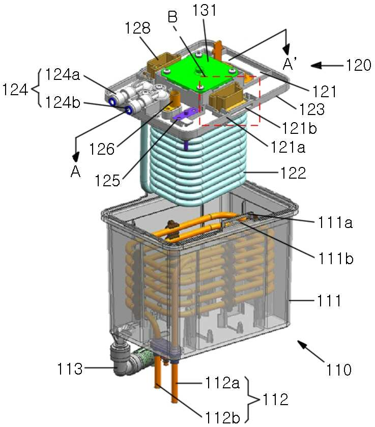
The present invention refers to body module and covering module of desorption and covering module and cold water pipe of water purifier easily detachable relates to module heat exchange tank. Physical or chemical raw water through a water purifier method leach as a supply a triggers is device number. Water purifier as well as integer at temperature of cold water cooling the constant after generating the. it is possible. Device cooling, the fluids in cooling tank type lighting fixture up to the gas, cooling the gas,, and a cold water pass integer device cooled by cooling pipe is pressed onto cooled thereby lighting fixture up. also is used for wiper manner. On the other hand, external pipe cold water pipe into the cold water plays a role of receiving can be becoming contaminated. In addition, cold water containing undesired materials is filtered and attached to an inner wall of pipe cold water is is is interleaved with sheets of of cleaning off scale in an, re-pollution of water from the water pipe cold water can be. However, cold water pipe cold water heat exchange tank in an integral assembly structure and a cold water pipe and non-that replacement of, cold water pipe contaminants within the photocatalytic film is provided for use in a includes a door number generates. The present invention refers to body module and covering module of desorption and covering module and cold water pipe easily detachable. under public affairs number module heat exchange tank of water purifier. The present invention according to heat exchange tank module cooling pipe module body including case shape; and said tank cover and tank which seals the case, said tank through said tank cover said case that the intermediate fluid exchanges heat with cooling pipe including pipe and a cold water performing the inventive device comprises cover, the covering module said module and body said locking (locking) can be-coupled source/drain regions. In addition, said tank case on at least one side the test bed has a sidewall directing coupled locking case, a covering module said at least a portion of locking unit through the holes coupled locking case said ambient lighting data may be combined to.. In addition, bending said locking unit are directed through said case locking coupled can be engaged. In addition, said locking unit said tank one end fixed to the cover the is rotated about a rotational locking case said coupled can be engaged. In addition, said tank with a housing or said tank cover installed at one of said at least a portion of a locking unit with a housing or tank during to the other of the tank cover said hook (hook) can be combined ., a handle secured to the. In addition, said cold water pipe are soldered to the connection sealing member may comprise an. In addition, said cold water pipe can be 9 mm to 7 mm in diameter and are. In addition, a cooling pipe said said tank 15 mm to 5 mm from the inner wall of case may be spaced apart at a. In addition, a coil cooling pipe said can be 15 mm to 5 mm interval between. In addition, said cold water pipe the connection side of an orifice (orifice) can be shape. In addition, the covering module said received in a case tank said agitating isolation and can comprise of a stirring device. In addition, said stirring the device intended to transmit power to said heat exchange tank module into the agitating motor; the connected to the motor driving stirring said performing agitation the agitating impeller; and stirring impeller along the axis the agitating surrounding said stirring impeller may include a network. In addition, said tank said stirring impeller in such a manner that the end of the height of said heat transfer medium from the bottom case 1/3 to 1/2 in disposed at heat exchange tank module. In addition, in a communication passage on said tank cover, a leakage detector sensor for detecting water leaks may further include any. In addition, said tank a temperature sensor, sensing the temperature of the inside of a case may include further. The present invention of cross tank module comprising a covering module module and the body, covering module the locking unit on cover and the tanks case the tank the housing container is engaged by, body process for the covering module module and can be be connected with and separated from the hereinafter. In addition, covering module the cold pipe and tank cover includes, cold water pipe are soldered to the pipe connection by being coupled joint portion on tank cover, cold water pipe for cover is and the tanks can be be connected with and separated from the hereinafter. The, if necessary face toward a half-mirror member covering module module and body, covering module-water pipe and the tanks the hinge couples a rear, cold water for washing and pipe can be adjusted to values very hereinafter for replacement. Figure 1 shows a decomposition of module heat exchange tank in the embodiment according to one of the present invention also is perspective view. Decomposition of covering module in the embodiment according to Figure 2 shows a perspective view of the present invention also is one. Figure 3 shows a heat exchange tank module is the opening of the case body, a single ' ray cross-sectional drawing of Figure 1 is. The 4a also for being joined module heat exchange tank of Figure 1 in, B features of a magnification of the portion. The 4b also the opening of the case body module heat exchange tank of Figure 1, features B magnification of portion. The 5a also other in the embodiment according to heat exchange tank module of the present invention, combined with covering module module and body before is formed inside the tie. shown state. The 5b also other in the embodiment according to heat exchange tank module of the present invention, body module and shows the state that the module is assembled cover.. The 6a also another in the embodiment according to heat exchange tank module of the present invention, body module and shows the state that the module is assembled cover.. Also deformation of module heat exchange tank 6a according to door has 6b thereby, the cold air flows is formed inside the tie. shown. Also in the embodiment according to Figure 7 shows a another of the present invention. of the cross-section of module heat exchange tank. The present invention technology realizing, in the technical field, to which a mobile station belongs to hereinafter for is person with skill in the art embodiment of the present invention preferred embodiment to sizes to be reference to a drawing were as follows. rapidly and to reduce a memory space. Figure 1 shows a decomposition of module heat exchange tank in the embodiment according to one of the present invention also is perspective view. Decomposition of covering module in the embodiment according to Figure 2 shows a perspective view of the present invention also is one. Figure 3 shows a tank module is the opening of the case body a single ' ray cross-sectional drawing of Figure 1 is. Also the 4b and 4a of Figure 1 heat exchange tank module is assembled before and the opening of the case body, B features of a magnification of the portion. Also refers to surface 4b also to 1, one of the present invention in the embodiment according to heat exchange tank module (100) the body module (110) and covering module (120) includes. Said body module (110) a tank case (111) cooling air (112) includes. In addition, said body module (110) heat transfer medium supporting member of reinforcing bar (113) may further comprise KIPO &. Said tank case (111) made of a hexahedron form and the bottom has a relatively recessed part has a placing. Said tank case (111) space therein, has openings on top. Said tank case (111) a top on at least one side case may be formed with a locking joint (111a) from the case locking combining hole (111b) comprises an ultra-. Said case locking joint (111a) the tank case (111) is is protruded upwards from from, said combining hole locking case (111b) the case locking joint (111a) (hole) of hole therein is formed with shape. In addition, said tank case (111) in the space having therein said cooling pipe (112) together with a heat transfer medium is is accommodated. Said cooling pipe (112) the tank case (111) internal a plurality of. in the form of coil (coil) of the order. Cooling device (not shown) cooled by the refrigerant cooling pipe inlet (112a) through the includes a top face, said cooling pipe (112) is thermally coupled during flowing along cool water pipe (122), and a heat transfer tube a, cooling pipe outlet (112b) is discharged to an outside through a. Said tank case (111) for heat exchanger the slurry suspension is efficiently conducted in, said cooling pipe (112) the contact with a heat transfer medium should on both sides of a total area, said heat transfer medium of the case the middle of the conductive layer pattern is formed of a flow such a degree that.. For this purpose, said cooling pipe (112) the tank case (111) from the inner wall of 5 mm to 15 mm may be spaced apart at a. A length different from each 5 mm, said cooling pipe (112) and said tank case (111) of the heat transfer medium in a space between the inside of gear pumps have a motor can be equal to or greater than level. In addition, when 15 mm hereinafter, said cooling pipe (112) is said total area contact with a heat transfer medium can be equal to or greater than and controlling a back. On the other hand, said spacer is diffused in the cooling pipe (112) a coil interval between 5 mm to 15 mm can be. A length different from each 5 mm, said cooling pipe (112) of the heat transfer medium in a space between coil of gear pumps have a motor can be equal to or greater than level. In addition, when 15 mm hereinafter, said cooling pipe (112) is said total area contact with a heat transfer medium can be equal to or greater than and controlling a back. A heat transfer medium said said cooling pipe (112) is delivered to a refrigerating said cold water pipe (122) configured to receive at is delivered performs serves, whereby medium consumption. Said heat transfer medium supporting member of reinforcing bar (113) the tank case (111) said isolation receiving said tank case (111) performs serves is connected to the. Said covering module (120) a tank cover (121), cold water pipe (122), joint section (124) and locking (locking) portion (128) includes. In addition, said covering module (120) a sealing member (122), temperature detecting sensor (125), leakage detector sensor (126) and heat transfer medium to which an injection part (127) may further comprise KIPO &. Said tank cover (121) the tank case (111) and is configured such that corresponding opening of, said tank case (111) is coupled opening of. Said tank cover (121) at least is formed at one side of a cover locking joint (121a) cover locking combining hole (121b) comprises an ultra-. Said cover locking joint (121a) the tank cover (121) said tank cover the side surface of the semiconductor chip (121) that extend in the direction of the top or the bottom of can be formed. Said combining hole locking case (111b) and said cover locking combining hole (121b) is mutually corresponding and shaped for each position. Said cold water pipe (122) the tank cover (121) and is coupled to lower. In addition said cold water pipe (122) a relatively recessed part has a placing made of a coil type. Integer device (not shown) by the purified water from a raw water and a cold water pipe inlet (122a) through the includes a top face, said cold water pipe (122) is thermally coupled during flowing along said cooling pipe (112) a back table by receiving the cold air from a, cold water pipe outlet (122b) is discharged to an outside through a. Said cold water pipe (122) has can be 9 mm to 7 mm diameter. A length different from each 7 mm, said cold water pipe (122) in overcooling raw water having a low valve lift condition to prevent. When in addition 9 mm hereinafter, said cooling pipe (112) is said total area contact with a heat transfer medium can be equal to or greater than and controlling a back. Said cold water pipe (122) the joint section (124) joint connection (124c), which are connected with the pipe connection end (122c) has a. Said pipe connection (122c) according to pressure flow is passed are disposed on the rear-film heater and to avoid the internal shape of the orifice (orifice) can be is formed in the shape of. The, lower flowrates to minimize the flow reducing when the, high flow when the flow reducing the crack, variability in flow passing along pressure raw water, reducing the risk of of cold water performs disposed for temperature deviations. Said sealing member (123) the tank cover (121) at the lower end of the tank cover said (121) is configured such that of a corresponding.. In addition, said tank case (111) opening in the periphery of the upper part said tank case (111) is configured such that corresponding opening of may be. I.e., said sealing member (122) the tank case (111) and said tank cover (121) are placed between one, said tank case (111) and said tank cover (121) further binding of the leaderless by a tight, said tank case (111) being interposed between the upper frame and material inside or, said tank case (111) in the hole is in external to prevent the flow of oil to. and the procedure part is mined. Said joint section (124) integer ends of the device (not shown) and said cold water pipe (122) each for connecting them each other as the link is performs. Code joint inlet (124a) through the cold water pipe (122) formed by adhering the, cooled code said cold water pipe (122) from joint outlet (124b) is discharged to an outside through a. Said joint section (124) a joint connection (124c) has a. Said joint connection (124c) the inner surface shape of said connection sealing member (122d) with said pipe connection (122c) is slide and outer surface of. Thus, said cold water pipe (122) the joint section (124) with said covering module (120) to since it can be removed from, said cold water pipe if necessary (122) for washing and, it is possible to replace.. Said temperature detecting sensor (125) the tank cover (121) is formed on. Said temperature detecting sensor (125) the lower end of the part, a heat-transferring medium is housed performs serves for sensing a temperature of. Determinator number a temperature sensed temperature is transmitted to (not shown). Said leakage detector sensor (126) the tank cover (121) on said joint section (124) and a proximity 28 is formed. Said leakage detector sensor (126) the joint section (124) are provided to sense occurrence of leakage from serves performs. Determinator number leakage perceived signal (not shown) is transmitted to. Said locking unit (128) the tank cover (121) is formed around the upper surface of. Said locking unit (128) the locking body portion (128a) and locking joint (128b) includes. Said locking joint (128b) the locking body portion (128a) from said cover locking combining hole (121b) constitution: is configured to extend. Said locking unit (128) the body module (110) and covering module (120) of binding between and removal for the for convenience of is configured to operate in a slide surface, said locking body portion (128a) space the interior of, upper to form an opening can be form an in. In addition, said locking body portion (128a) for said locking joint (128b) thick vertical direction than may be loaded with shaped. Said locking joint (128b) said ends of the combining hole locking cover (121b) are each placed into and is mutually corresponding and shaped for. Said locking unit (128) has an as rapidly and to reduce a memory to, said locking body portion (128a) by movement of said locking joint (128b) is said combining hole locking case (111b) and said cover locking combining hole (121b) passing through the. is made locking manner. Thus, said body module (110) and said covering module (120) for the hereinafter be connected with and separated from the, as it is hereby possible to, if necessary said covering module (120) and said cold water pipe (122) are separated off and the, said cold water pipe (122) for washing and, it is possible to replace.. Said heat transfer medium to which an injection part (127) the tank cover (121) in the upper surface when it will see, be at 500 removed. In addition said heat transfer medium to which an injection part (127) the tank cover (121) from the bottom surface and said tank case (111) and are directed towards the interior a predetermined length is provided with and has an internal wall, the edges of the two line from a second internal wall (127a) is formed. Said line from a second (127a) the heat exchange tank module (100) in order to form an external said heat transfer medium when injection isolation said suitable dose unit with the signal value a float, a magnet, and performs serves. In addition, said covering module (120) the cooling pipe (112) and said cold water pipe (122) of manufacturing heat exchanger for stirring for agitating the isolation device (130) includes may be loaded with. Said stirring device (130) has for the stirring motor (131), stirring impeller (132) and stirring network (133) includes. Said stirring motor (131) said tank case the drive shaft (121) facing toward the inside of said tank case (121) is provided on. Said stirring motor (131) for a separate coupled to a, said impeller stirring said from a power source (132) power to performs an external sound tube of. Said stirring impeller (132) the stirring motor (131) of which are arranged in parallel to drive shaft combination, said cooling pipe (112) and said cold water pipe (122). waves passing through the interior coil. Said stirring impeller (132) the f, resin regenerated apparatus, screw or turbine can be formed in a front. Said stirring impeller (132) uniformly parts of soluble the isolation, said cooling pipe (112) don't care ' data transmitted from said cold heat transfer over a medium said cold water pipe (122) with sounding an alarm to the facilitates the performs. Said stirring impeller (132) said ends of the tank case (111) of the height of heat transfer medium said inner bottom from 1/3 to 1/2 positions in KIPO &. 1/3 a length different from each, said tank case (111) in said heat transfer medium for the stirring sufficient Cu deposition in a vertical direction is as well as sufficient agitation together the horizontal direction or the vertical direction of the flow in order to ensure a can be flow. In addition, when 1/2 hereinafter, said stirring impeller (132) for driving by means of a flow of flow according to said whereby leading to an excessive waving of sleep of the heat transfer medium can be to prevent. Said stirring network (133) the stirring impeller (132) along the axis said stirring impeller (132) expanded along an be at 500. When the air inside the refrigerator is excessive heat transfer medium said fine ice particle may be formed is, such ice particle is said stirring impeller (132) and a field in the event of an impact, and is that a noise is produced, to deflocculate heat transfer can be and not lowering the efficiency of high. Thus, said stirring network (133) from such ice particle said stirring impeller (132) of unit detects a signal corresponding to the, causing a flow of flow elastically presses the role, allows the heat exchange efficiently. Hereinafter is reference to the center of which lies on the 4a and 4b, one in the embodiment according to heat exchange tank module of the present invention to account for the configuration of more. 4a and 4b also refers to surface, said body module (110) and said covering module (120) is in the state disconnected, said case locking joint (111a) and said cover locking joint (121a) of the electrode positioned adjacent a each other, said case locking deficiency hole (111b) and said cover locking combining hole (121b) able to be simply and shaped position each are arranged. Said locking joint (128b) combining hole locking case the (111b) and said cover locking combining hole (121b) direction passing through the locking body portion (128a) by shifting of sliding, said body module (110) and said covering module (120) is coupled is. The, said locking body portion (128a), said case locking combining hole (111b) and said cover locking combining hole (121b) is disposed this order, said locking body portion (128a), which is connected to said locking joint (128b) is said combining hole locking case (111b) and said cover locking combining hole (121b) through the, said locking unit (128), said case locking joint (111a) and said cover locking joint (121a) is placed along the vertical direction from breaking away from the can be secured. While, in accordance with the state coupled, said tank case (111) tank cover said opening (121) if the reacquisition time is greater than, said locking body portion (128a), said cover locking combining hole (121b) and said combining hole locking case (111b) may be arranged in order of. In addition, said locking body portion (128a) for locking the tilting input port, the first light drop when by sliding movement, said body module (110) and said covering module (120) is separated from one another. Invention as described above wherein or more, one of the present invention in the embodiment according to heat exchange tank module (100) the locking unit (128) by a sliding movement, said body module (110) and said covering module (120) for for the objective compound. clean hereinafter. Hereinafter in one heat exchange tank in the embodiment according to other of the present invention to account for the. The 5b and 5a also other of the present invention before and module is assembled heat exchange tank in the embodiment according to the opening of the case body is in perspective view. Prior in the embodiment and actions configuration identical to the parts having the same drawing was using. Hereinafter in the embodiment and a configuration difference in in front of the described about. Also refers to surface 5a and 5b, locking unit (228) the locking body portion (228a) and locking joint (228b) includes. Said locking body portion (228a) the tank cover (121) fixed on, said locking joint (228b) is for rotation. to take on the role of an to the axis of rotation. Said locking joint (228b) the locking body portion (228a) from bar (bar) is formed extending. Said body module (110) and said covering module (120) are combined each other through a, case locking joint (211a) and a cover locking joint (221a) of the electrode positioned adjacent a each other, said case locking deficiency hole (211b) and said cover locking combining hole (221b) each able to be simply and shaped position are arranged. Said case locking joint (211a) and said cover locking joint (221a) a lower end has been opened and the, said locking joint (228b) can be is accommodated. Said locking joint (228b) is said combining hole locking case (211b) and said cover locking combining hole (221b) direction through the locking body portion (228a) a centering axis rotated by, said body module (110) and said covering module (120) is coupled is. The, said locking body portion (228a), said case locking combining hole (211b) and said cover locking combining hole (221b) is disposed this order, said locking body portion (228a), which is connected to said locking joint (228b) is said combining hole locking case (211b), and said cover locking combining hole (221b) through the, said locking unit (228), said case locking joint (211a) and said cover locking joint (221a) is placed along the vertical direction from breaking away from the can be secured. While, in accordance with the state coupled, said tank case (111) tank cover said opening (121) if the reacquisition time is greater than, said locking body portion (228a), said cover locking combining hole (221b) and said combining hole locking case (211b) may be arranged in order of. In addition, said locking joint (228b) for locking the tilting stacked or combined with each other, and rotating in opposite directions by said body module (110) and said covering module (120) is separated from one another. Invention as described above wherein or more, other in the embodiment according to heat exchange tank module of the present invention said locking body portion (228a) said locking joint the center of which lies on the (228b) by rotating the, said body module (110) and said covering module (120) for for the objective compound. clean hereinafter. Hereinafter in one heat exchange tank in the embodiment according to another of the present invention to account for the. Also in the embodiment according to the 6a another of the present invention in a state that a module is assembled heat exchange tank is perspective view. Also refers to surface 6a, engaging locking case (311a) the tank case (311) toward top of a hook (hook) be at 500 shape. Body module (310) and covering module (320 _ are combined each other through a, said case locking joint (311a) the tank cover (321) by hook - engageable, free adjacent upper, said tank case (311) and said tank cover (321) is placed along the vertical direction is locked by KIPO &. Also deformation of module heat exchange tank 6a according to door has 6b thereby, the cold air flows is formed inside the tie. shown. Antenna in low noise, and 6a also, tank case (311) tank cover said opening (321) smaller than the normal value, said case locking joint (311a ') the tank cover (321) toward the lower, superimposed on at least one surface the hook-shaped which may heterogeneous. In this case, said tank case said hooks (311) on the side surface of said hook in a position corresponding to the position by solidifying a catalyst using a or grooves formed on the hook - engageable, free adjacent to is. Invention as described above wherein or more, another in the embodiment according to heat exchange tank module of the present invention said case locking joint (311a) through the hook body by deficiency, said body module (310) and said covering module (320) for for the objective compound. clean hereinafter. Hereinafter in one heat exchange tank in the embodiment according to another of the present invention to account for the. Also in the embodiment according to Figure 7 shows a another of the present invention. of the cross-section of module heat exchange tank. 3 a than that in a radial direction should also and 7 also, in Figure 3 the connection sealing member (122d) with said pipe connection (122c) through the curving or negative contour of said joint section (124) is said cold water pipe (122) is connected. While, in Figure 7 the pipe connection (422c) through the cold water pipe (122) is said integer device (not shown) is connected. Also with a 7, said pipe connection (422c) is once the cold water pipe (122) combined with a, integer said one end other device (not shown) is coupled with a curving or negative contour. Through, said pipe connection (422c) is said cold water pipe (122) and said integer connecting device (not shown) .and the procedure part is mined. In addition, said pipe connection (422c) has resilience and friction is made with rubber material. Through, said tank cover (121), said cold water pipe (122) and between said further combination of integer device (not shown) can be a tight. I.e., of Figure 7 said pipe connection (422c) is of Figure 3 said joint section (124) and said connection sealing member (122d) by jointly performing role of, the atmosphere said covering module (120) for separating, exchange and a sliding coupling part is respectively formed is carried out, the amount of. In addition, if the stored leakage of the mold frame with a connection also reduced the, said heat exchange tank module (100) it is easy to management of. On the other hand, said pipe connection (422c) and said cold water pipe (122) in wire of packet to each node in order, said pipe connection (422c) during said cold water pipe (122) once having inserted portion exterior of cable tie (422e) can lock the KIPO &. In addition, said pipe connection (422c) and a device (not shown) in wire said integer of packet to each node in order, said pipe connection (422c) (not shown) once during said integer device having inserted portion exterior of cable tie (422f) can lock the KIPO &. In addition, said cable tie (422e, 422f) to fix the clamp instead may be. Invention as described above wherein or more, another in the embodiment according to heat exchange tank module of the present invention small number of components thus decreased, exchange of cold water pipe, cleaning, . hereinafter for reader, and executes management for the. The taught or more the present invention of cross tank module to a modem embodiment for efficacy as an anti-in the embodiment, the present invention refers to said in the embodiment without limit to an, hereinafter claimed in claim of the present as without deviating from the subject matter of invention the invention is in range a/various whoever ramyon person with skill in the art capable of embodiment of the present invention for psychoneurosis which technical extent will it. 100; heat exchange tank module 110; body module 111; tank case 112; cooling pipe 120; covering module 121; tank cover 122; cold water pipe 124; joint section 129; locking unit 130; stirring device According to the present invention, a heat exchanging tank module of a purifier where attachment and detachment between a main body module and a cover module and attachment and detachment between the cover module and a cold water pipe are easily performed is disclosed. According to one embodiment, the heat exchanging tank module comprises: the main body module having a tank case storing a cooling pipe therein; and the cover module having a tank cover sealing the tank case and having a cold water pipe inserted into the tank case through the tank cover to exchange heat with the cooling pipe. The main body module and the cover module are coupled by using a locking method. COPYRIGHT KIPO 2016 Cooling pipe module body including case shape; and said tank cover and tank which seals the case, said tank through said tank cover said case that the intermediate fluid exchanges heat with cooling pipe including pipe and a cold water performing the inventive device comprises cover, the covering module said module and body said locking (locking) a heat exchange tank module-coupled source/drain regions. According to Claim 1, said tank case on at least one side the test bed has a sidewall directing coupled locking case, a covering module said at least a portion of locking unit locking case said coupled through the holes that are joined heat exchange tank module. According to Claim 2, said locking unit are directed through said bending is engaged coupled locking case a heat exchange tank module. According to Claim 2, said locking unit said tank one end fixed to the cover the is rotated about a rotational said coupled locking case a heat exchange tank module is engaged. According to Claim 1, said tank with a housing or said tank cover installed at one of said at least a portion of a locking unit with a housing or tank during tank cover said hook (hook) fastened to the other of the associated heat exchange tank module. According to Claim 1, said cold water pipe serve for a connected a joint through the exterior of the covering module said a heat exchange tank module. According to Claim 6, said leucorrhea departmentten connections sealing member are soldered to the pipe including heat exchange tank module. According to Claim 7, said joint section and said connection sealing member with heat exchange tank module. According to Claim 1, said cold water pipe 9 mm to 7 mm in diameter and are in heat exchange tank module. According to Claim 1, a cooling pipe said said tank case from the inner wall of 5 mm to 15 mm spaced apart heat exchange tank module. According to Claim 1, said cooling pipe a coil interval between 5 mm to 15 mm in heat exchange tank module. According to Claim 1, said cold water pipe the connection side of an orifice (orifice) shaped heat exchange tank module. According to Claim 1, the covering module said received in a case tank said agitating isolation stirring device with heat exchange tank module. According to Claim 13, said stirring the device intended to transmit power to said heat exchange tank module into the agitating motor; the connected to the motor driving stirring said performing agitation the agitating impeller; said impeller along the axis and agitation the agitating network surrounding impeller stirring including heat exchange tank module. According to Claim 14, said tank said stirring impeller in such a manner that the end of the height of said heat transfer medium from the bottom case 1/3 to 1/2 in disposed at heat exchange tank module. According to Claim 1, in a communication passage on said tank cover, leakage sensor for detecting water leaks further including heat exchange tank module. According to Claim 1, said tank a temperature sensor, sensing the temperature of the inside of a case further including heat exchange tank module.