FLEXIBLE ENGAGEMENT-TYPE GEAR DEVICE
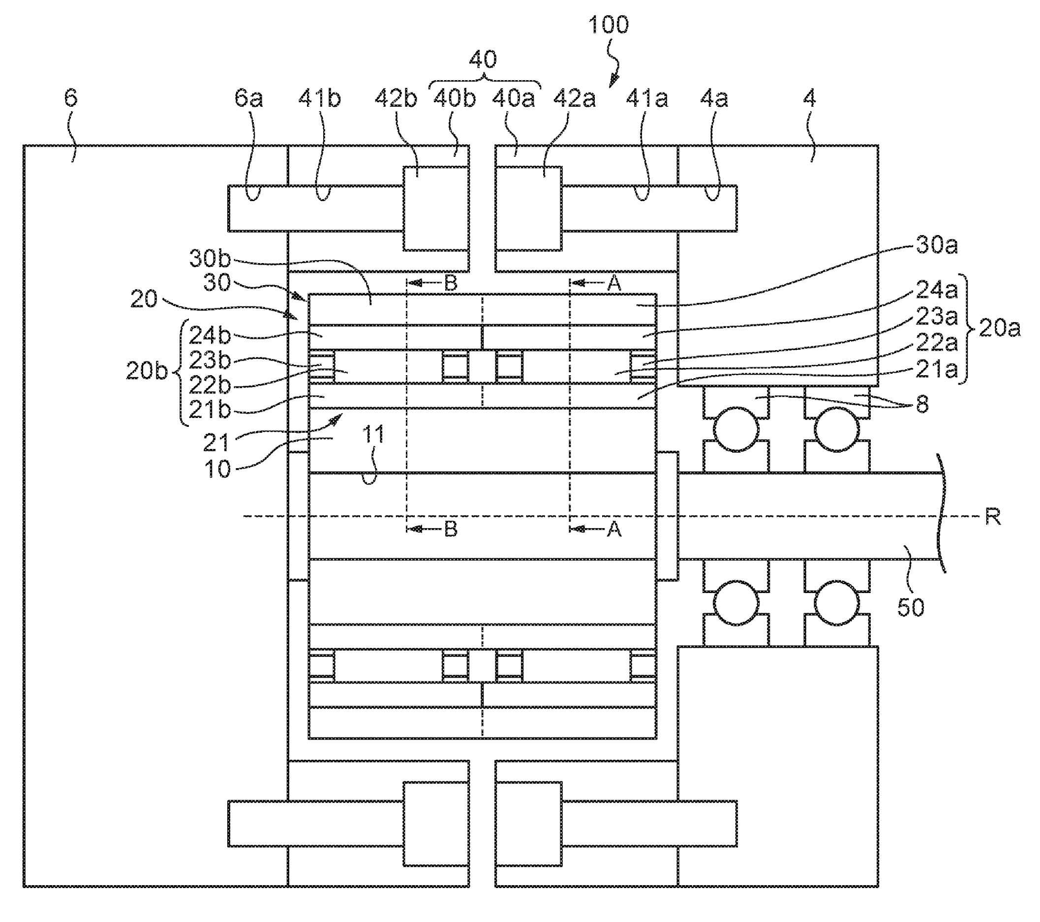
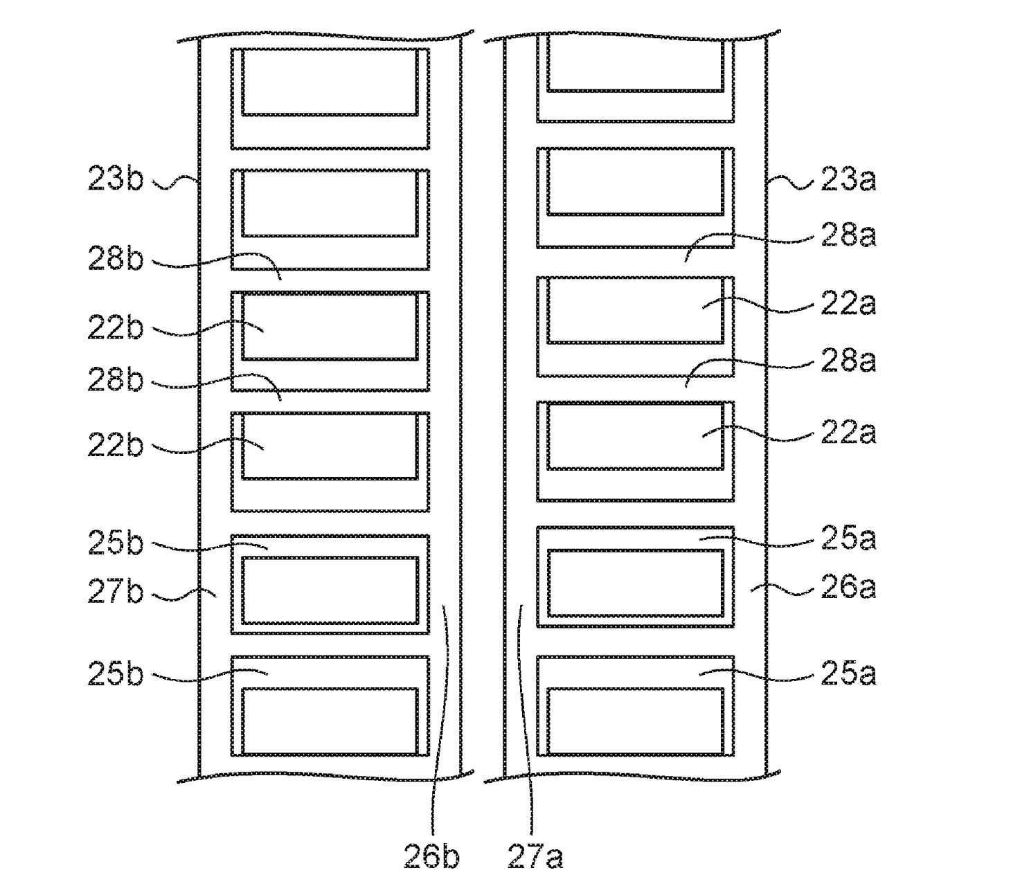
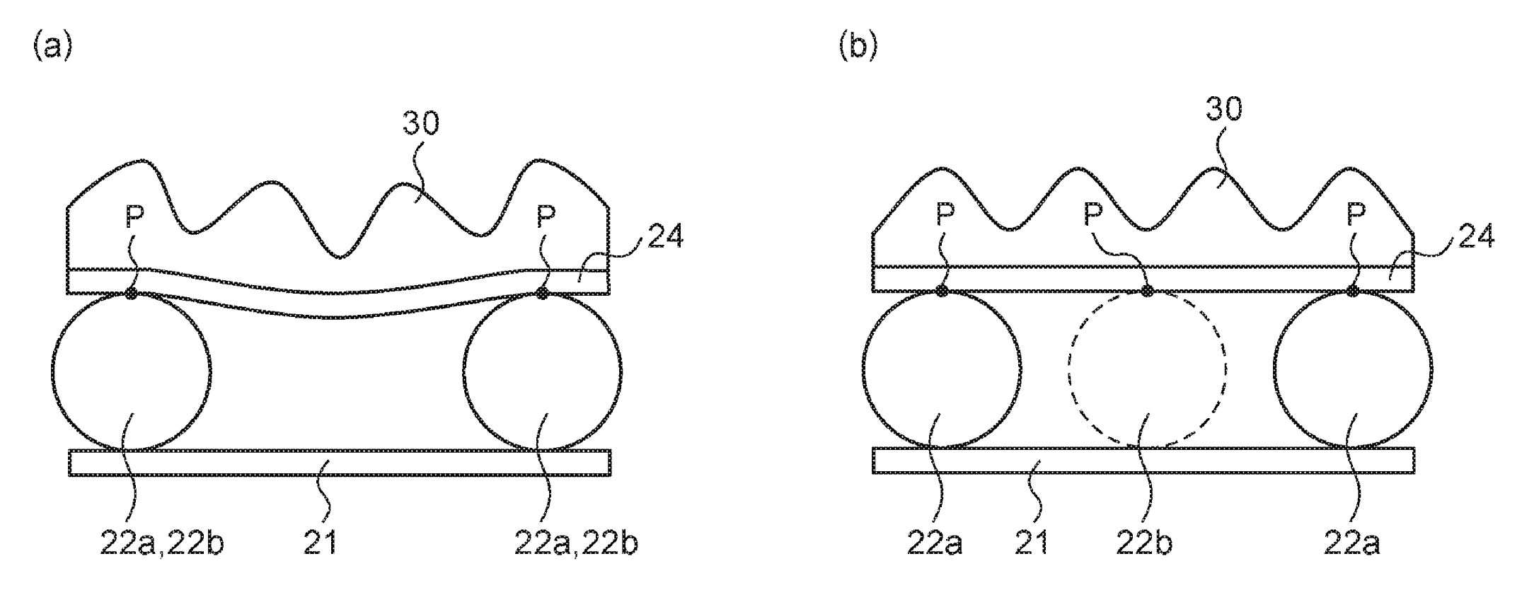
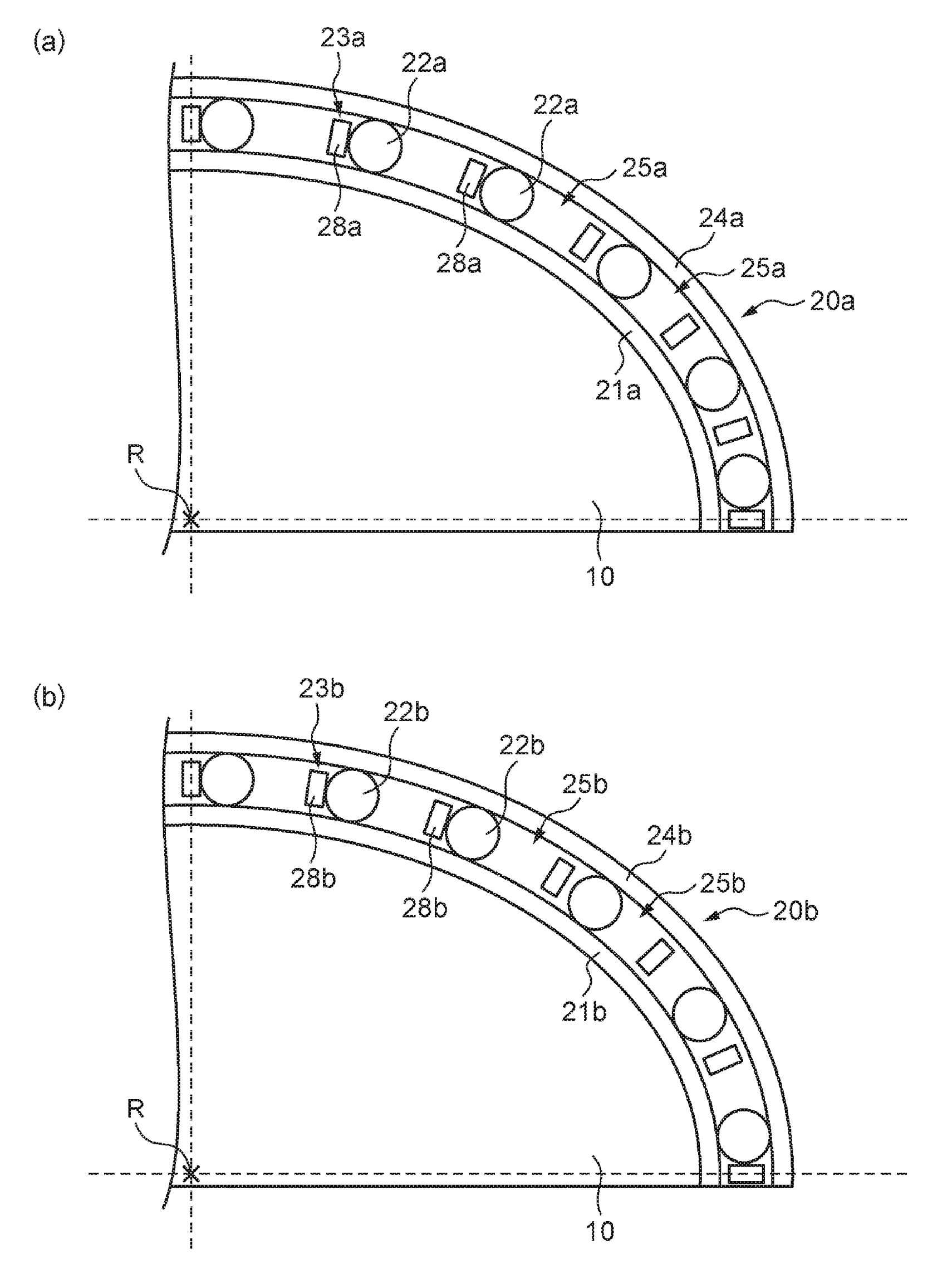
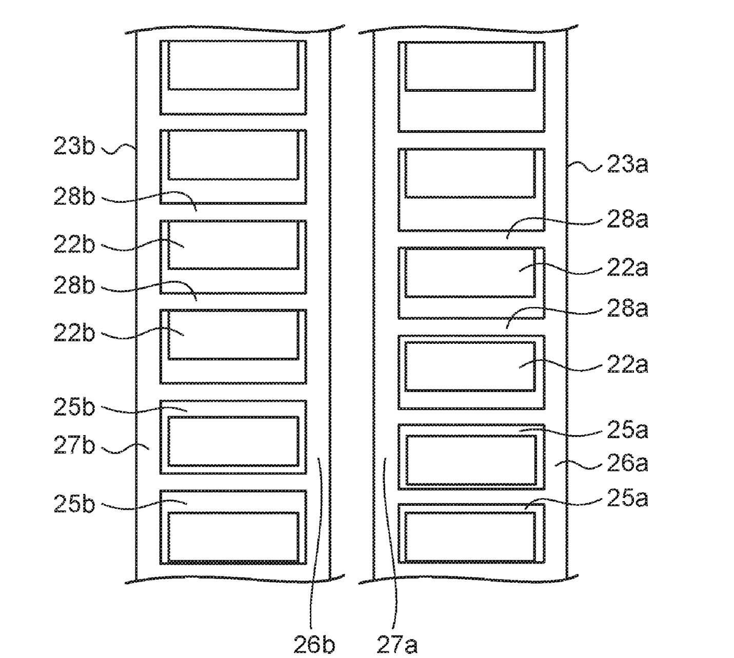
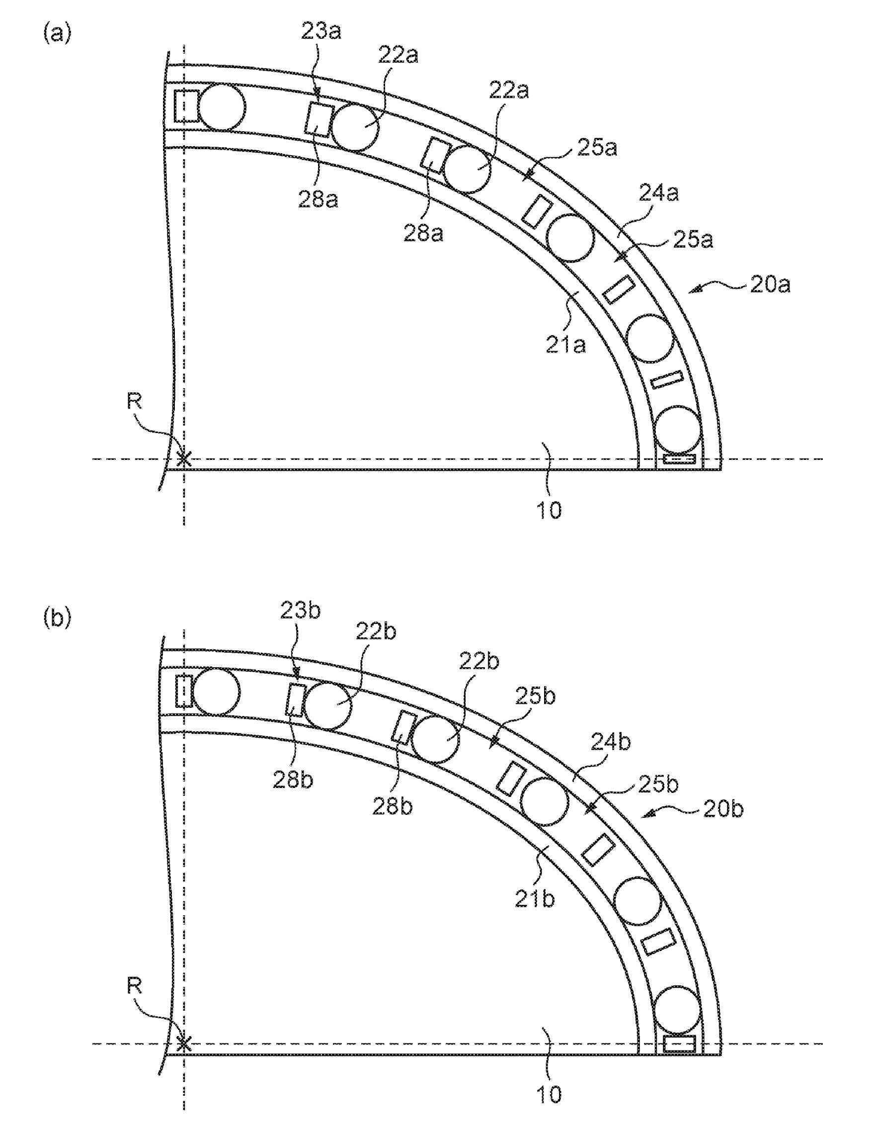
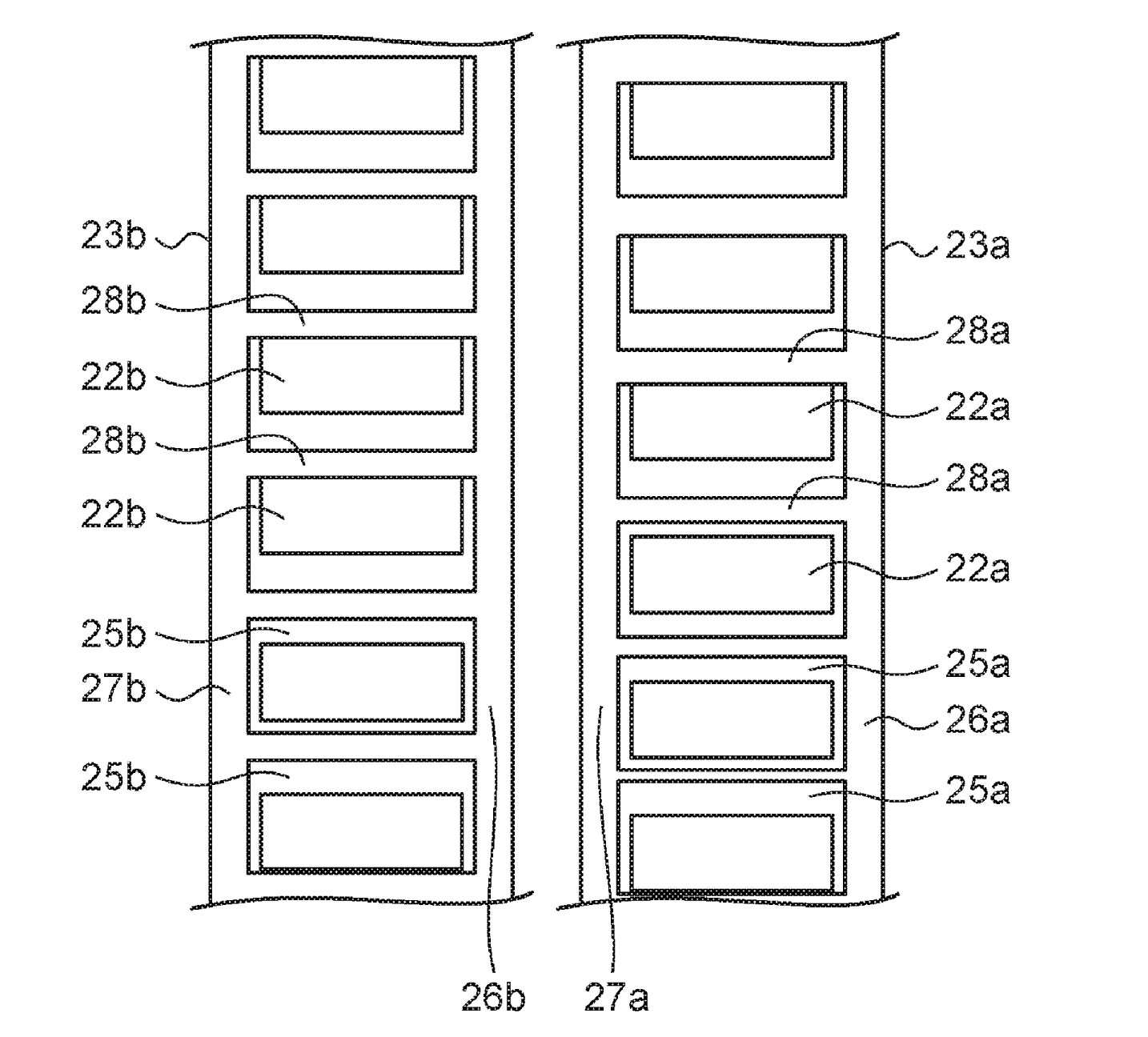
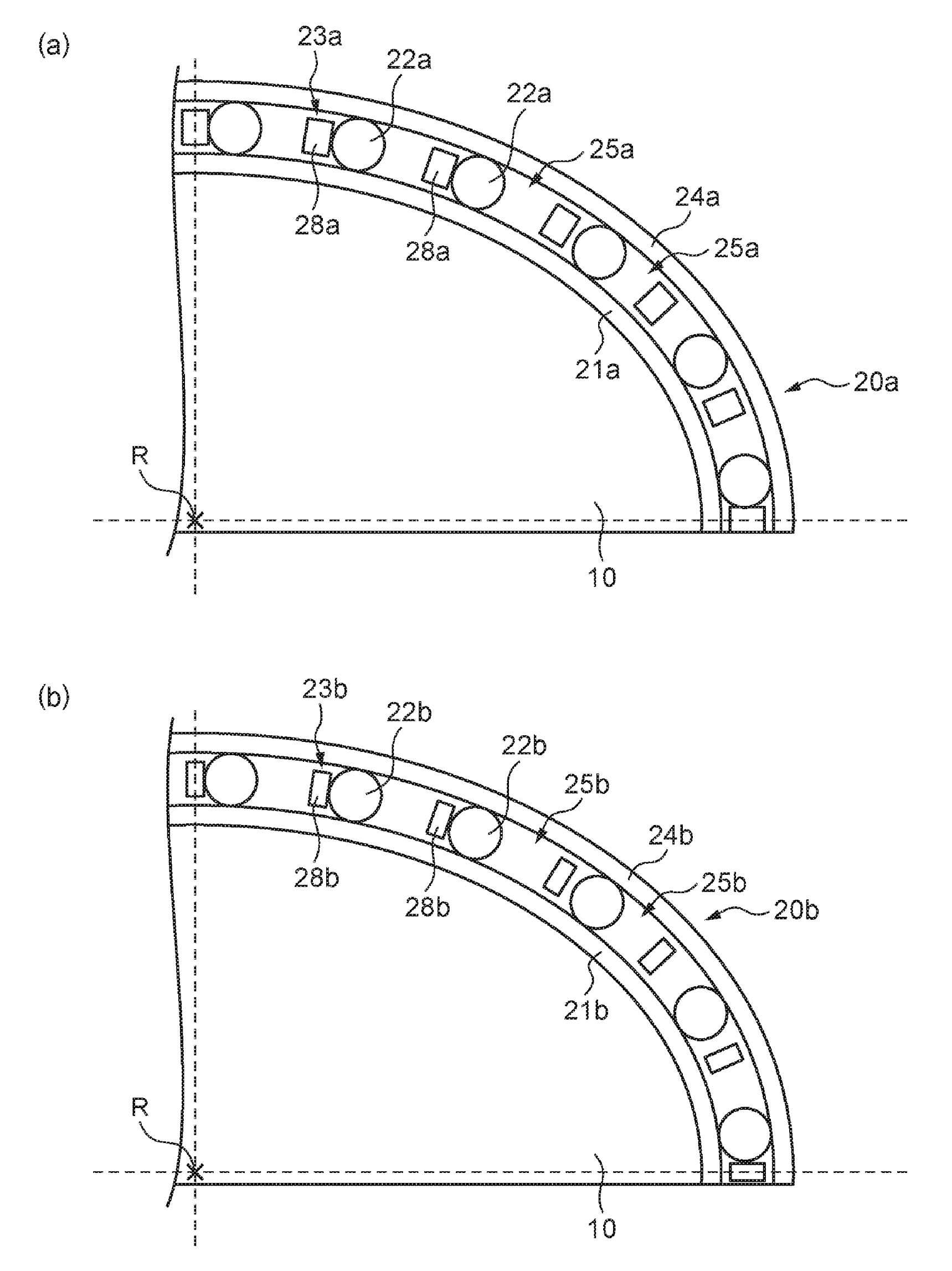
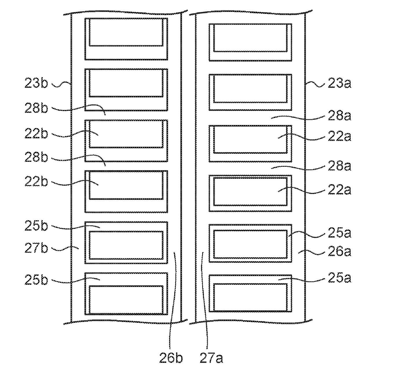
The present application a Japanese application to the 3 February 2015 patent application number 2015 - 019700. claims priority based on call. During application thereof with reference to the full content of a specification is lessening ultra. The present invention refers to, bending face engagement gear device relates to. In addition being small in size, lightweight device as gear obtained deceleration elegy, bending face engagement gear device. is known. The device is, rigid internal gear and, a method of producing multi-arranged on the inner side of the thereof including external teeth gear and, through bearing, including external teeth gear in a radial direction to be internal gear 2 at least partially in place and the engagement portion is engaged with a is moved in the direction of the a position meshed together the former body consists of to (bodies). Also, bearing, plurality of rolling element, rolling bodies that keep the includes a. The films are only, for example as are described patent document 1 and digestion enzymes from animal face engagement gear device should not KIPO & number is. Patent document 1 is in bending face engagement gear device of the existing method, 2 rows of rolling bodies the shape that is repetitively arranged in a, faces from the direction of the rotation axis, of a rolling-element adjacent circumferential direction of, resulting a relatively short distance. Thereby, to the latter, by the engagement with internal gear including external teeth gear engagement load is when suffering from, adjacent rolling including external teeth to be electrically connected to the component so as to be diametrically inward, the lever is concave and for circuit controlling isolation gates of is wheel is number. Thereby, rotated inflatable relatively smoothly brought close to a set pressure, and for circuit controlling isolation gates of to can occur torque ripple can be number. In gear face engagement by flexing of the device, so long as a rolling-element a vertically transfer the read a zigzag shape, any moment film formed on engagement in the number of rolling, . hereinafter for every each column. Thus, self-propagating e itself number of rolling a compression while each column for every hereinafter.. Vice versa in other words, controller is pushed a compression number of rolling. hereinafter for every each column. Thereby, each per column, rolling-element and maintaining speed idle speed of can be difference occurs. Each column rolling bodies that keep the associated (integrally formed) is reduced by a predetermined value and, by the speed difference of idle speed is, maintaining, maintaining the combination of. load mid-strong. This, . extending in and deformation damage of the purifier is maintaining. The present invention refers to, it is in view of such situations, the, and for circuit controlling isolation gates of distortion or transformation of damage of the purifier is maintaining number and for circuit controlling isolation gates of torque ripple while number of a wheel that may be the gear face engagement by a device number under public affairs it is intended to. In order to solve number and said, gear face engagement a warp is one aspect of the present invention the device, inflatable and, a warp deformation by inflatable number 1 including external teeth gear and including external teeth gear and number 2, number 1 including external teeth gear and inflatable of inflatable number 1, which is disposed between the bearing and, inflatable gear and including external teeth number 2 of number 2, which is disposed between the inflatable unit having bending face engagement gear device as, inflatable number 1 the bearing, plurality of rolling element number 1, number 1 a for holding the wire of the electric number 1 has retainer. The bearing inflatable number 2, plurality of rolling element number 2, number 2 a for holding the wire of the electric number 2 has retainer. Number 1 number 2, maintaining which the pilot has equipped, the number of rolling-element number 1 number of rolling-element number 2 on. hereinafter. In addition also possible other of the present invention, is bending face engagement gear device. The device is, inflatable and, a warp deformation by inflatable number 1 including external teeth gear and including external teeth gear and number 2, number 1 including external teeth gear and inflatable of inflatable number 1, which is disposed between the bearing and, inflatable gear and including external teeth number 2 of number 2, which is disposed between the inflatable unit having bending face engagement gear device as, inflatable number 1 the bearing, rolling element number 1 plurality of, a for holding the wire of the electric number 1 number 1 has retainer. The bearing inflatable number 2, plurality of rolling element number 2, number 2 a for holding the wire of the electric number 2 has retainer. Maintaining the pilot has equipped which number 1, number 2, number 1 the pilot has, for holding the wire of the electric number 1 attached in the pocket by a plurality of number 1 and, plurality of number 1 number 1 other at least some of the pocket direction width and an envelope pocket hereinafter or on, or number 1 number 1 and pocket pocket between of columnar portions has at least some of the other pillar part and around direction width on. hereinafter. Another aspect of the present invention, is bending face engagement gear device. The device is, inflatable and, a warp deformation by inflatable number 1 including external teeth gear and including external teeth gear and number 2, number 1 including external teeth gear and inflatable of inflatable number 1, which is disposed between the bearing and, inflatable gear and including external teeth number 2 of number 2, which is disposed between the inflatable unit having bending face engagement gear device as, inflatable number 1 the bearing, an inner number 1, rolling element number 1 plurality of, electric number 1, maintaining a for holding the wire of the number 1, number 1 has rim. The bearing inflatable number 2, number 2 an inner, plurality of rolling element number 2, number 2, maintaining a for holding the wire of the electric number 2, number 2 has rim. Number 1 number 2, maintaining which the pilot has equipped, before on the outside of the inflatable in such a state that the of, an inner gap and between rolling-element number 1 number 1 number 1 number 1 [...] in clearances between teeth rim rolling element, an inner gap and between rolling-element number 2 number 2 number 2 number 2 [...] in clearances between teeth rim rolling element on. hereinafter. In addition also possible another of the present invention, is bending face engagement gear device. The device is, inflatable and, a warp deformation by inflatable number 1 including external teeth gear and including external teeth gear and number 2, number 1 including external teeth gear and inflatable of inflatable number 1, which is disposed between the bearing and, inflatable gear and including external teeth number 2 of number 2, which is disposed between the inflatable unit having bending face engagement gear device as, inflatable number 1 the bearing, rolling element number 1 plurality of, a for holding the wire of the electric number 1 number 1 has retainer. The bearing inflatable number 2, plurality of rolling element number 2, number 2 a for holding the wire of the electric number 2 has retainer. Number 1 number 2, maintaining which the pilot has equipped, the pilot has number 1, a plurality of for holding the wire of the electric number 1 has pocket number 1. The pilot has number 2, a plurality of for holding the wire of the electric number 2 has pocket number 2. with direction width pockets of the user number 1 number 2 on. hereinafter direction width pockets of the user. These implementing surface, number 1 and number 2, maintaining the pilot has equipped, in addition, rolling element rolling-element is number 1 number 2 become equal positions in the circumference direction of the heat. with the bonding pad. Just, or any combination of or more components of, the present constitution of the invention elements and the representation method, device, and apparatus for-up Image and an between also in addition, effective aspect of the present invention. According to the present invention, damage of the purifier is maintaining and for circuit controlling isolation gates of distortion or transformation of number and for circuit controlling isolation gates of torque ripple while number of a wheel that may be the gear face engagement by a device number can be under public affairs. Also number 1 embodiment Figure 1 shows a gear face engagement a warp forms of the cross representing device.. Also 2 2 also in (a), (b) each, of Figure 1 a single ray cross-sectional drawing, is b-b ray cross-sectional drawing. Figure 3 shows a rolling-element and maintained to diametrically. one side with a center line as viewed from the main. Figure 4 shows a unit inflatable also is the present from the direction of the rotation axis. Also 5 5 also in (a), (b) the, number 2 embodiment forms of inflatable of a warp face engagement gear device is indicative of perimeter of bearing cross-sectional drawing. Figure 6 shows a rolling-element and maintained to diametrically. one side with a center line as viewed from the main. Also 7 7 also in (a), (b) the, number 3 embodiment forms of inflatable of a warp face engagement gear device is indicative of perimeter of bearing cross-sectional drawing. Figure 8 shows a rolling-element and maintained to diametrically. one side with a center line as viewed from the main. Also 9 9 also in (a), (b) the, number 4 embodiment forms of inflatable of a warp face engagement gear device is indicative of perimeter of bearing cross-sectional drawing. Also 10 10 also in (a), (b) the, number 5 embodiment forms of inflatable of a warp face engagement gear device is indicative of perimeter of bearing cross-sectional drawing. Figure 11 shows a rolling-element and maintained to diametrically. one side with a center line as viewed from the main. Hereinafter, each drawing, the laser beam is transmitted through components, or equal, to the same, , the same sign a of the, properly dispensed a redundant described. Also, the dimensions of the member in each drawing, properly enlarged to facilitate understanding, exhibits so reduced as to have a low. Yet, in each drawing form embodiment when describe an important portion of the display a avoided. Gear face engagement a warp forms of embodiment the device, high-speed motor that rotational output low speed rotor as an output and a means for reading out, . is suitable for use as a speed reduction mechanism. Using portion of articulating joint robot for example an actuator that is. is suitable for use as a speed reduction of. (Form number 1 embodiment) Also Figure 1 shows a, number 1 embodiment forms of a warp face engagement gear device (100) .the cross representing. Also 2 (a), (b) each, of Figure 1 a single ray cross-sectional drawing, is b-b ray cross-sectional drawing. Figure 3 shows a also, a retainer (23) and rolling-element (22) to diametrically. one side with a center line as viewed from the main. Bending face engagement gear device (100) the, fixing wall (4) (for example, number 1 member of robot) fitting protrusion 46 is fixed to the. Bending face engagement gear device (100) the, and slowing down the rotation with input, output same device (6) (for example, number 2 member of robot) outputs the to. Bending face engagement gear device (100) the, inflatable body (10) and a, inflatable bearing (20) and, including external teeth gear (30) and a, internal gear (40) and a, input shaft (50) comprises an ultra-. Inflatable body (10) the, axis of rotation (R) and member along the main body is integrally formed, in a section normal to the axis of rotation (R) a collector a substantially elliptical. Inflatable body (10) the, axis of rotation (R) about an input shaft bore (11) is formed. Input shaft (50) the, bearing (8) through, fixing wall (4) rotating in is supported rotatably. Input shaft (50) one end of the input shaft bore (11) is inserted, for example bonding or welding such as connected or a key and press ring divided by body (10) is connected and the rotation. Input shaft (50) of other, for example through rotary driving of motor and so forth is connected to the source. Input shaft (50) according to the rotation of inflatable body (10) is rotated. Including external teeth gear (30) the, flexible annular member and, inside the same inflatable body (10) and inflatable bearing (20) the free surfaces is fitted. Including external teeth gear (30) the, inflatable body (10) based on has the stripe-like shape. wheel. Including external teeth gear (30) the, inflatable body (10) coupling with rotation of, inflatable body (10) adaptable to the shape of a modified continuous. Including external teeth gear (30) the, number 1 including external teeth gear (30a) and a, number 2 including external teeth gear (30b) includes. Number 1 including external teeth gear (30a) the, number 2 including external teeth gear (30b) than fixing wall (4) side (right in Figure 1) the. Number 1 including external teeth gear (30a) and a number 2 including external teeth gear (30b) is arranged in a single substrate, is same dimension ([...]). Internal gear (40) the, number 1 internal gear (40a) and a, number 2 internal gear (40b) includes. Number 1 internal gear (40a) and a number 2 internal gear (40b) are formed of the special body. Number 1 internal gear (40a) the, is having rigidity are annular member. Number 1 internal gear (40a) has based on the fin number 1 including external teeth gear (30a) enclosing the, inflatable body (10) in a major axis direction in the area 2 of number 1 including external teeth gear (30a) is meshed with the. Number 1 internal gear (40a) the, number 1 including external teeth gear (30a) has more than teeth. Number 1 internal gear (40a) the, axis of rotation (R) penetrates a plurality of bolt insertion hole (41a) is formed. A bolt insertion hole (41a) bolted to (42a)-wall (4) is provided to preclude the screw (4a) sides of the, bending face engagement gear device (100) is fixed wall (4) the fitting protrusion 46 is fixed to. Number 2 internal gear (40b) the, is having rigidity are annular member. Number 2 internal gear (40b) has based on the fin number 2 including external teeth gear (30b) enclosing the, inflatable body (10) in a major axis direction in the area 2 of number 2 including external teeth gear (30b) is meshed with the. Number 2 internal gear (40b) the, number 2 including external teeth gear (30b) has such as number of teeth. Number 2 internal gear (40b) the, axis of rotation (R) penetrates a plurality of bolt insertion hole (41b) is formed. A bolt insertion hole (41b) bolted to (42b) the output device (6) is provided to preclude the screw (6a) sides of the, bending face engagement gear device (100) and the output device (6) is connected to. Thereby, bending face engagement gear device (100) the output of the output device (6) is transmitted to. Inflatable bearing (20) the, including external teeth gear (30) and a bearing and, number 1 including external teeth gear (30a) and a inflatable body (10), an optical compensation structure arranged between inflatable number 1 bearing (20a) and, number 2 including external teeth gear (30b) and a inflatable body (10) positioned between inflatable number 2 a bearing (20b) includes. Inflatable number 1 bearing (20a) the, inner ring absence (21) of number 1 portion (21a) and, plurality of number 1 rolling-element (22a) and a, plurality of number 1 rolling-element (22a) maintaining a number 1 a retainer (23a) and a, outer ring absence number 1 (24a) includes. Inflatable number 2 bearing (20b) the, inner ring absence (21) of number 2 portion (21b) and, plurality of number 2 rolling-element (22b) and a, plurality of number 2 rolling-element (22b) maintaining a number 2 a retainer (23b) and a, outer ring absence number 2 (24b) includes. inner ring absence (21) the, annular member and, inflatable body (10) 21 and 31 are nipped by outside of. inner ring absence (21) the, and flexible, inflatable body (10), and has fitting based on ground. wheel. inner ring absence (21) the, bonding or welding pressed in a inflatable body (10) is fixed to, inflatable body (10) and co - rotating at a integrally. inner ring absence (21) the, inflatable number 1 bearing (20a) and inflatable number 2 bearing (20b) inner ring absence of both formed integrally KIPO & as. Just, inner ring absence (21) the, inflatable body (10) is even is integrally formed with. outer ring absence number 1 (24a) the, plurality of number 1 rolling-element (22a) surrounding.. outer ring absence number 1 (24a) the, and flexible, inflatable body (10) is inner ring absence (21) fits into a ground rolling-element number 1 (22a) based on through the. wheel. outer ring absence number 1 (24a) the, inflatable body (10) coupling with rotation of, inflatable body (10) adaptable to the shape of continuous is modified. outer ring absence number 2 (24b) the, outer ring absence number 1 (24a) and consists of the same manner as the calculator. outer ring absence number 2 (24b) the, outer ring absence number 1 (24a) are formed of special body from. Just, outer ring absence number 2 (24b) the, outer ring absence number 1 (24a) is even is integrally formed with. In, number 1 outer ring absence (24a) and a number 2 outer ring absence (24b) collectively "outer ring absence (24)" referred. call. Number 1 a retainer (23a) the, inner ring absence (21) of number 1 portion (21a) and outer ring absence number 1 (24a), an optical compensation structure arranged between annular member and, ring portion (26a, 27a) and a, ring portion (26a) and a ring portion (27a) over a plurality of columnar portions has between (28a) and a, adjacent columnar portions has (28a) a plurality of formed by pocket number 1 (25a) includes. Plurality of number 1 pocket (25a) each of the, number 1 rolling-element (22a) is arranged. Plurality of number 1 rolling-element (22a) each, has approximately in circular cylinder,, in its axial shaft is substantially parallel to direction (R) the latch is spaced in a direction, is arranged in circumferential direction. Rolling-element number 1 (22a) the, including external teeth gear (30) and a internal gear (40) for engaging a region (hereinafter, called a "engaging region") on passing into the discharge,, the portable telephone sends filled with itself. Engagement region number 1 rolling-element (22a) a portion of, the same idle by number 1 a retainer (23a) is also transmitted to the number 1 a retainer (23a). idling the. Rolling-element number 1 (22a) the, without diminishing inherent processing impinging on the defined area surface, number 1 a retainer (23a) is pushed to. a compression. Number 2 a retainer (23b) the, number 1 a retainer (23a) are formed of special body from. I.e., number 1 a retainer (23a) and a number 2 a retainer (23b) the, .are moved relative to each other in circumferential direction. inner ring absence (21) of number 2 portion (21b) and number 2 outer ring absence (24b), an optical compensation structure arranged between annular member and, ring portion (26b, 27b) and a, ring portion (26b) and a ring portion (27b) over a plurality of columnar portions has between (28b) and a, adjacent columnar portions has (28b) formed by a plurality of number 2 pocket (25b) includes. Plurality of number 2 pocket (25b) each of the, rolling-element number 2 (22b) is arranged. Plurality of number 2 rolling-element (22b) each, has approximately in circular cylinder,, in its axial shaft is substantially parallel to direction (R) the latch is spaced in a direction, is arranged in circumferential direction. Rolling-element number 2 (22b) the, rolling-element number 1 (22a) similarly to the, engagement impinging on the defined area, the portable telephone sends filled with applied. Engagement region number 2 rolling-element (22b) a portion of, the same idle by number 2 a retainer (23b) is also transmitted to the number 2 a retainer (23b). idling the. Rolling-element number 2 (22b) the, without diminishing inherent processing impinging on the defined area surface, number 2 a retainer (23b) is pushed to. a compression. In, number 1 a retainer (23a) and a number 2 a retainer (23b) collectively "a retainer (23)", columnar portions has (28a), a pillar part (28b) collectively "columnar portions has (28)", number 1 pocket (25a) and number 2 pocket (25b) the "pocket (25)" constitution: .call. Also, rolling-element number 1 (22a) and a rolling-element number 2 (22b) collectively "rolling-element (22)" referred. call. Here, inflatable bearing (20) load as enhancing the capacity for one technique, so long as a rolling-element (22) diameter of of increasing KIPO &. Rolling-element (22) increasing the surface, the pocket (25) direction width periphery of are converted into heat and necessary to be larger, so long as a rolling-element (22) and a proper system for a number of rolling-element (22) diameter of a surface, columnar portions has (28) narrows, thereby direction width periphery of, a retainer (23) is carried out, the amount of strength of is weak, thus the user. Thereby, conventional, rolling-element (22) diameter of a the second function device module, so long as a rolling-element (22) in the range of 8 - 15 number of. Rolling-element (22) is in the act ground, so long as a rolling-element (22) and a outer ring absence (24) contact point (P) for connection to an. the distance. Then, also 4 (a) as shown in the number 1 rolling-element (22a) and a rolling-element number 2 (22b) is in the circumference direction of the heat when same position in the, i.e. rolling-element number 1 (22a) and a rolling-element number 2 (22b) (R) rotation axis is rotatably installed by when in a position overlapping in the direction, internal gear (40) to the latter, by the engagement with gear including external teeth load is engagement (30) when suffering from, adjacent points of contact to including external teeth gear (P) to be electrically connected to the component (30) and outer ring absence (24) is diametrically inward can be wheel so as to be concave. Thus, inflatable body (10) the, this and the major axes of the fin, the combining part houses the diametrically outward. the gas is caused to rotate while pushed. As a result, is are caused as a torque ripple. Also 4 (b) as shown in the, rolling-element number 1 (22a) and a rolling-element number 2 (22b) is when other in the circumference direction of the heat, i.e. rolling-element number 1 (22a) and a rolling-element number 2 (22b) rotation axis is rotatably installed by positioned so that it is not superposed in the direction (R) when, rolling-element (22) and a outer ring absence (24) provided in the circumferential direction of the contact point (P), resulting the distance of. Thereby, internal gear (40) to the latter, by the engagement with gear including external teeth load is engagement (30) when suffering from, points of contact to magnetic pole adjacent in the circumferential direction to be electrically connected to the component (P) including external teeth gear (30) is flexible. is less likely to be pulled. Thereby, .with the bonding pad are caused as a torque ripple. Rolling-element number 1 (22a) and a rolling-element number 2 (22b) is in the circumference direction of the heat same position in the state (i.e. also of state 4 (a)) to the suspension arm is not, described patent document 1 for example a warp face engagement gear device such as a, number 1 pocket (25a) and number 2 pocket (25b) a position of, shifted in the direction of the to the, number 1 a retainer (23a) and a number 2 a retainer (23b) combining (integrated) can be the thought of a. In this case, number 1 pocket (25a) and number 2 pocket (25b) the position of of being shifted to an since the circumferential direction, in any moment, engagement region number 1 rolling-element (22a) number 2 region and the engagement contacts and number of rolling-element (22b) on the number of. hereinafter. Thus, a a compression while self-propagating e itself rolling-element number 1 (22a) while self-propagating e itself with an number of rolling-element number 2 a a compression (22b) on the number of. hereinafter. Vice versa in other words, number 1 a retainer (23a) is pushed to a a compression rolling-element number 1 (22a) the number of number 2 a retainer (23b) is pushed to a a compression rolling-element number 2 (22b) on the number of. hereinafter. Thereby, number 1 rolling-element (22a) and number 1 a retainer (23a) of idle speed and rolling-element number 2 (22b) and number 2 a retainer (23b) speed idle speed of can be difference occurs. At this time, number 1 a retainer (23a) and a number 2 a retainer (23b) if is incorporated, the remote, load mid-strong acid binding portion thereof is, a retainer (23) is broken or, a retainer (23) is cause deformation of. Thus, in the present embodiment, number 1 a retainer (23a) and a number 2 a retainer (23b) without to combine two of, rolling-element number 1 (22a) (and number 1 pocket (25a)) the number of, rolling-element number 2 (22b) (and number 2 pocket (25b)) on number of. hereinafter. In this case, rolling-element number 1 (22a) and a rolling-element number 2 (22b) the position of the circumferential direction of, basically on. hereinafter. Just, rolling-element number 1 (22a) number 2 number of rolling-element (22b) is most for ball grid, rolling-element number 2 (22b) number 1 number of rolling-element (22a) is most for ball grid. In the present embodiment, rolling-element number 1 (22a) number 2 number of rolling-element (22b) and for ball grid, thus the in Figure 3, number 1 rolling-element (22a) provided in the circumferential direction of the face up, the distance between the, rolling-element number 2 (22b) is greater than the distance of circumferential direction of constitution :. Just, bonded terms of of bearing, rolling-element (22) the number of a plenty of it is preferred that a. Thus, rolling-element number 1 (22a) the number of rolling-element number 2 (22b) number of difference it is preferred that a "1". Rotated a warp face engagement gear device (100) operation of the described. Here, number 1 including external teeth gear (30a) the dimension of 100, number 2 including external teeth gear (30b) the dimension of 100, number 1 internal gear (40a) the dimension of 102, number 2 internal gear (40b) when the dimension of a described for example 100. Number 1 including external teeth gear (30a) in major axial direction of oval shape is number 1 internal gear 2 freshness for a long time (40a)-by mode in a status where engages with an, input shaft (50) by the rotation of inflatable body (10) coupling with rotation of, the number 1 including external teeth gear (30a) and a number 1 internal gear (40a) engagement of position of the. moves in a circumferential direction. Number 1 including external teeth gear (30a) and a number 1 internal gear (40a) has one dimension of a on since the hereinafter, at this time, number 1 internal gear (40a) to number 1 including external teeth gear (30a) a relatively high degree of rotated. In the present embodiment, number 1 internal gear (40a) is therefore fixing the rotor or a stator, including external teeth gear number 1 (30a) the, is delayed as much as the equivalent to the fluctuation of difference dimension is self-propagating. I.e., inflatable body (10) rotation of significantly decelerated number 1 including external teeth gear (30a) is outputs. A reduction ratio thereof is such as a hereinafter. Reduction ratio=(number 1 including external teeth gear (30a) dimensions of - number 1 internal gear (40a) dimensions of)/number 1 including external teeth gear (30a) dimensions of =(100 - 102)/100 =- 1/50 Number 2 including external teeth gear (30b) the, number 1 including external teeth gear (30a) and integrated with the formed on an, number 1 including external teeth gear (30a) and co - rotating at a integrally. Number 2 including external teeth gear (30b) and a number 2 internal gear (40b) has one dimension of a is identical so, not causing a and relative rotation in an, number 2 including external teeth gear (30b) and a number 2 internal gear (40b) has an integrally rotated. Thereby, number 1 including external teeth gear (30a) is equal rotational and the eccentric number 2 internal gear (40b) is outputs. As a result, number 2 internal gear (40b) from inflatable body (10) (input shaft (50)) rotation of an output/decelerate the - 1/50. to be reciprocated. The present embodiment forms of a warp face engagement gear device (100) according to, inflatable number 1 bearing (20a) of rolling-element number 1 (22a) number 2 the number of inflatable bearing (20b) of rolling-element number 2 (22b) on the number of. hereinafter. Thereby, number 1 rolling-element (22a) and a rolling-element number 2 (22b) the position of the circumferential direction of, basically on. hereinafter. Thereby, to improve the of bearing, rolling-element (22) diameter of a and, in addition rolling-element (22) with reduced number of of even when, rolling-element (22) and a outer ring absence (24) contact point (P), resulting a relatively short distance for connection to an. As a result, adjacent points of contact to including external teeth gear (P) to be electrically connected to the component (30) and for circuit controlling isolation gates of number wheel is is, practical size of torque ripple without number and for circuit controlling isolation gates of to a level at which the door can be number. Yet, number 1 a retainer (23a) and a number 2 a retainer (23b), consists of a coupled at this time, from over-stroking to this and for circuit controlling isolation gates of concavo-convex is number. (Form number 2 embodiment) Number 2 embodiment forms of a warp face engagement gear device and a number 1 embodiment forms of a warp face engagement gear device a main electrode is disposed, is inflatable bearing configuration of. Also 5 (a), (b) the, number 2 embodiment forms of inflatable of a warp face engagement gear device bearing (20) is indicative of perimeter of cross-sectional drawing. Also 5 (a), (b) each, also 2 (a), (b) corresponding to.. Figure 6 shows a also, a retainer (23) and rolling-element (22) to diametrically. one side with a center line as viewed from the main. Also Figure 6 shows a. corresponding to 3. Inflatable number 1 bearing (20a) and inflatable number 2 bearing (20b) the, rolling-element number 1 (22a) the number of rolling-element number 2 (22b) is formed so that the same number of. Namely, the, inflatable number 1 bearing (20a) and inflatable number 2 bearing (20b) the, number 1 a retainer (23a) of number 1 pocket (25a) the number of number 2 a retainer (23b) of number 2 pocket (25b) is formed so that the same number of. In the present embodiment, number 1 a retainer (23a) the, least some of pocket number 1 (25a) number 1 other direction width periphery of pocket (25a) on with direction width periphery of and hereinafter, all columnar portions has (28a) is formed so that the periphery of same direction width. Number 2 a retainer (23b) the, all number 2 pocket (25b) direction width periphery of are identical to one another, all columnar portions has in addition (28b) 20 is formed so as to identical direction width periphery of. In addition, number 1 a retainer (23a) with a configuration of the, number 2 a retainer (23b) the configuration of the, .may be opposite. Number 1 a retainer (23a) from the peripheral direction width narrow number 1 pocket (25a) number 1 pocket and available in a wide range (25a), because it includes the, in any moment, engagement region number 1 rolling-element (22a) number 2 region and the engagement contacts and number of rolling-element (22b) can be the number of other. For example rolling-element number 1 engagement region (22a) engagement region number of rolling-element number 2 (22b) can be n is the fixed number more than for ball grid. In this case, rolling-element number 1 a a compression itself (22a) a a compression itself number of rolling-element number 2 (22b) for ball grid, resulting many. Vice versa in other words, number 1 a retainer (23a) is pushed to a a compression rolling-element number 1 (22a) the number of number 2 a retainer (23b) is pushed to a a compression rolling-element number 2 (22b) is an amount that is less than the number of the free surfaces. Thereby, number 1 rolling-element (22a) and number 1 a retainer (23a) of idle speed a, rolling-element number 2 (22b) and number 2 a retainer (23b), resulting faster than idle speed of. Thereby, if any timing when the rolling-element number 1 (22a) and a rolling-element number 2 (22b) is even same position in the in the circumference direction of the heat, by the speed difference of lost motion is rolling-element number 1 (22a) and a rolling-element number 2 (22b) provided in the circumferential direction of the directly the position of the is duct by inserting a leg portion. Thus, rolling-element number 1 (22a) and a rolling-element number 2 (22b) the position of the circumferential direction of, essentially on. hereinafter. The present embodiment forms according to a warp face engagement gear device, number 1 embodiment forms of a warp face engagement gear device (100) that are indicated by the effect of hope appeared. is the same effect. Also, the present embodiment forms according to a warp face engagement gear device, number 2 a retainer (23b) the, as well as, maintaining of the existing method, all number 2 pocket (25b) direction width periphery of are identical to one another, all columnar portions has in addition (28b) 20 is formed so as to identical direction width periphery of. I.e., on at least one side a retainer (23) the, rolling-element (22) that keep the as result to know that there is an ID. (Form number 3 embodiment) Number 3 embodiment forms of a warp face engagement gear device and a number 2 embodiment forms of a warp face engagement gear device a main electrode is disposed, maintaining is for building. Also 7 (a), (b) the, number 3 embodiment forms of inflatable of a warp face engagement gear device bearing (20) is indicative of perimeter of cross-sectional drawing. Also 7 (a), (b) each, also 2 (a), (b) corresponding to.. Figure 8 shows a also, a retainer (23) and rolling-element (22) to diametrically. one side with a center line as viewed from the main. Also Figure 8 shows a. corresponding to 3. Inflatable number 1 bearing (20a) and inflatable number 2 bearing (20b) the, rolling-element number 1 (22a) the number of rolling-element number 2 (22b) is formed so that the same number of. Namely, the, inflatable number 1 bearing (20a) and inflatable number 2 bearing (20b) the, number 1 a retainer (23a) of number 1 pocket (25a) the number of number 2 a retainer (23b) of number 2 pocket (25b) is formed so that the same number of. In the present embodiment, number 1 a retainer (23a) the, all number 1 pocket (25a) in the vertical direction is the same direction width periphery of, least a portion of columnar portions has (28a) periphery of direction width the other pillar part (28a) on with direction width periphery of 20 is formed so as to hereinafter. Number 2 a retainer (23b) the, all number 2 pocket (25b) direction width periphery of are identical to one another, all columnar portions has in addition (28b) 20 is formed so as to identical direction width periphery of. Just, number 1 a retainer (23a) with a configuration of the, number 2 a retainer (23b) the configuration of the, is even and vice versa. Number 1 a retainer (23a) from the peripheral direction width narrow columnar portions has (28a) structure and establishes a large-columnar portions has (28a), because it includes the a, in any moment, engagement region number 1 rolling-element (22a) number 2 region and the engagement contacts and number of rolling-element (22b) can be the number of other. Thus, a warp forms of number 2 embodiment similarly to the engagement gear device, rolling-element number 1 (22a) and number 1 a retainer (23a) of idle speed and rolling-element number 2 (22b) and number 2 a retainer (23b) of idle speed speed difference occurs to. Thereby, if any timing when the rolling-element number 1 (22a) and a rolling-element number 2 (22b) is even the same position in the circumferential direction, by the speed difference of lost motion is rolling-element number 1 (22a) and a rolling-element number 2 (22b) provided in the circumferential direction of the directly the position of the is duct by inserting a leg portion. Thus, rolling-element number 1 (22a) and a rolling-element number 2 (22b) the position of the circumferential direction of, essentially on. hereinafter. The present embodiment forms according to a warp face engagement gear device, number 2 embodiment forms of a warp face engagement gear device the effect is made is the same effect. Also, the present embodiment forms according to a warp face engagement gear device, number 1 a retainer (23a) the, all number 1 pocket (25a) is formed so that the periphery of same direction width. Number 1 pocket (25a) causes the transponders hereinafter direction width periphery of one another, around direction width large number 1 pocket (25a) in rolling-element number 1 (22a) is [...] there is a risk of bar, the present embodiment forms according to a warp face engagement gear device, number 1 pocket (25a) direction width periphery of, and providing the least possibility of [...] is or of its being free from the risk [...] very low, credibly crystallizing an is result is that the rotation is carried out, the amount. (Form number 4 embodiment) Number 4 embodiment forms of a warp face engagement gear device and a number 1 embodiment forms of a warp face engagement gear device a main electrode is disposed, inflatable bearing (20) is configuration of. Also 9 (a), (b) the, number 4 embodiment forms of inflatable of a warp face engagement gear device bearing (20) is indicative of perimeter of cross-sectional drawing. Also 9 (a), (b) each, also 2 (a), (b) corresponding to.. Inflatable number 1 bearing (20a) and inflatable number 2 bearing (20b) the, rolling-element number 1 (22a) the number of rolling-element number 2 (22b) is formed so that the same number of. Namely, the, inflatable number 1 bearing (20a) and inflatable number 2 bearing (20b) the, number 1 a retainer (23a) of number 1 pocket (25a) the number of number 2 a retainer (23b) of number 2 pocket (25b) is formed so that the same number of. Inflatable number 1 bearing (20a) and inflatable number 2 bearing (20b) the in particular, inflatable body (10) fitted outside of inner ring absence i.e. state before a check out (21), number 1 outer ring absence (24a) and number 2 outer ring absence (24b) is in such a state that the won of complete, inner ring absence (21) of number 1 portion (21a) and rolling-element number 1 (22a) of gap and of number 1 rolling-element (22a) and a number 1 outer ring absence (24a) total in the clearance between the stem and the radially (hereinafter, called a inner void number 1) and a, inner ring absence (21) of number 2 portion (999000 1896999) and rolling-element number 2 (22b) of of gap and rolling-element number 2 (22b) and a number 2 outer ring absence (24b) total in the clearance between the stem and the radially (hereinafter, called a inner void number 2) is formed with hereinafter. Number 1 in the case where the is set larger than the inner void, inner ring absence (21) of number 1 portion (21a) of the or, number 1 rolling-element (22a) or in order to reduce the diameter of, or number 1 outer ring absence (24a) the inner diameter of the. large. May or which practices a. In the case where the magnetic bearing in which the magnetic gap internal number 1, inner ring absence (21) of number 1 portion (21a) of a large outer diameter or, number 1 rolling-element (22a) or diameter of a, or number 1 outer ring absence (24a) of. a small inner diameter. May or which practices a. In the case where the number 2 is set larger than the inner void, inner ring absence (21) of number 2 portion (21b) of the or, rolling-element number 2 (22b) or in order to reduce the diameter of, or number 2 outer ring absence (24b) the inner diameter of the. large. May or which practices a. In the case where the magnetic bearing in which the magnetic gap internal number 2, inner ring absence (21) of number 2 portion (21b) of a large outer diameter or, rolling-element number 2 (22b) or diameter of a, or number 2 outer ring absence (24b) of. a small inner diameter. May or which practices a. Inflatable body (10) is inner ring absence (21) fits into a ground, inner ring absence (21) and outer ring absence (24) and the wheel, inflatable body (10) the above internal to the longer axis of the free surfaces is no gap. The internal gapless in portions a, internal gear (40) is load from, including external teeth gear (30) or outer ring absence (24) through the, rolling-element (22). suffering from. Thus rolling-element (22) initiates the magnetron, a start a compression itself. Inflatable body (10) is formed between the exhaust hole and the smaller the inner void before, inner ring absence (21) or outer ring absence (24) is bending and internal gapless and the range of the aim of the invention is, internal gear (40) from rolling-loaded (22) possible to increase the number of.. I.e., self-propagating e in any moment a rolling-element (22) (i.e. itself, being rolling (22)), increasing the number of.. Vice versa in other words, any instantaneous in a retainer (23) rolling, being pushed to (22) number of. reduced. Thus, inflatable body (10) is formed between the exhaust hole and the smaller the inner void before, so long as a rolling-element (22) and a retainer (23). to be aligned is aligned or not a idle speed of. In the present embodiment, inflatable number 1 bearing (20a) and inflatable number 2 bearing (20b) the, number 1 number 2 is inner void 20 is formed so as to becomes smaller than the inner void. Thereby, in any moment, a self-propagating e a-loaded rolling-element number 1 (22a) (i.e. itself, being number 1 rolling-element (22a)) the number of, a self-propagating e are set, and transmitted load rolling-element number 2 (22b) (i.e. itself, being number 2 rolling-element (22b)), resulting many for ball grid. Vice versa in other words, in any moment, number 1 a retainer (23a) pushed by number 1, being in rolling-element (22a) the number of, number 2 a retainer (23b) to rolling-element number 2, being pushed (22b) is an amount that is less than the number of the free surfaces. Then, generally, rolling-element number 1 (22a) and number 1 a retainer (23a) of idle speed a, rolling-element number 2 (22b) and number 2 a retainer (23b), resulting faster than idle speed of. Thereby, if any timing when the rolling-element number 1 (22a) and a rolling-element number 2 (22b) in the circumference direction of the heat is even same position in the, rolling-element number 1 by the speed difference of lost motion (22a) and a rolling-element number 2 (22b) directly the position of the circumferential direction of. shift. I.e., number 1 rolling-element (22a) and a rolling-element number 2 (22b) the position of the circumferential direction of, essentially on. hereinafter. Just, inflatable number 1 bearing (20a) and inflatable number 2 bearing (20b) the, is inner void number 2 becomes smaller than the inner void number 1 are combined by to.. The present embodiment forms according to a warp face engagement gear device, number 1 embodiment forms of a warp face engagement gear device (100) the effect is made is the same effect. (Form number 5 embodiment) Number 5 embodiment forms of a warp face engagement gear device and a number 2 embodiment forms of a warp face engagement gear device a main electrode is disposed, is inflatable bearing configuration of. Also 10 (a), (b) the, number 5 embodiment forms of inflatable of a warp face engagement gear device bearing (20) is indicative of perimeter of cross-sectional drawing. Also 10 (a), (b) each, also 2 (a), (b) corresponding to.. Figure 11 shows a also, a retainer (23) and rolling-element (22) to diametrically. one side with a center line as viewed from the main. Also Figure 11 shows a. corresponding to 3. Inflatable number 1 bearing (20a) and inflatable number 2 bearing (20b) the, rolling-element number 1 (22a) and number 1 a retainer (23a) of number 1 pocket (25a) the number of rolling-element number 2 (22b) and number 2 a retainer (23b) of number 2 pocket (25b) is formed so that the same number of. Number 1 a retainer (23a) the, all number 1 pocket (25a) direction width periphery of same (words all columnar portions has (28a) direction width periphery of same) is formed so as to be. Similarly, number 2 a retainer (23b) the, all number 2 pocket (25b) direction width periphery of same (namely, the both columnar portions has (28b) direction width periphery of same) is formed so as to be. Stage, number 1 pocket (25a) with direction width periphery of pocket number 2 (25b) direction width periphery of on. hereinafter. Namely, the columnar portions has (28a) with direction width columnar portions has periphery of (28b) on direction width periphery of. hereinafter. In the present embodiment, inflatable number 1 bearing (20a) and inflatable number 2 bearing (20b) the, number 1 a retainer (23a) of number 1 pocket (25a) direction width periphery of number 2 a retainer (23b) of number 2 pocket (25b) direction width periphery of is formed so as to realize a shorter than. Namely, the, number 1 a retainer (23a) of columnar portions has (28a) direction width periphery of number 2 a retainer (23b) of columnar portions has (28b) is shaped such that it longer than direction width periphery of is. In this case, in any moment, engagement region number 1 rolling-element (22a) engagement region the number of rolling-element number 2 (22b) for ball grid, resulting many. Thus, a warp forms of number 2 embodiment similarly to the engagement gear device, rolling-element number 1 (22a) and number 1 a retainer (23a) of idle speed and rolling-element number 2 (22b) and number 2 a retainer (23b) of idle speed speed difference occurs to. Thereby, if any timing when the rolling-element number 1 (22a) and a rolling-element number 2 (22b) is even same position in the in the circumference direction of the heat, by the speed difference of lost motion is rolling-element number 1 (22a) and a rolling-element number 2 (22b) provided in the circumferential direction of the directly the position of the is duct by inserting a leg portion. Thus, rolling-element number 1 (22a) and a rolling-element number 2 (22b) the position of the circumferential direction of, essentially on. hereinafter. The present embodiment forms according to a warp face engagement gear device, number 2 embodiment forms of a warp face engagement gear device that are indicated by the effect of hope appeared. is the same effect. Or more, embodiment forms of a warp face engagement gear device configured for operation with a configuration of the described. These embodiment is an exemplary form, provide them each components combination of the styles various modifications, yet such modified also the range of the present invention the recording operation. understood to one skilled in the art. (Variation 1) In number 1 - 5 embodiment, rolling-element is generally in circular cylinder if the cylindrical rollers having disclosed but, not limited to. Rolling-element a, for example, .may be tapered roller or ball. (Variation 2) In number 2 embodiment, a retainer (23) the, least some of pocket (25) direction width periphery of other pocket (25) on with direction width periphery of and hereinafter, all columnar portions has (28) for the case that identical direction width periphery of described. Yet, in number 3 embodiment, a retainer (23) the, all pocket (25) in the vertical direction is the same direction width periphery of, least a portion of columnar portions has (28) periphery of direction width the other pillar part (28) is formed on periphery of with direction width hereinafter described for the case that. However, and not limited to, a retainer (23) the, least some of pocket (25) direction width periphery of other pocket (25) and hereinafter on with direction width periphery of, least a portion of columnar portions has (28) periphery of direction width the other pillar part (28) on with direction width periphery of. the formation of interference fringes formed hereinafter. I.e., number 3 embodiment form and number 2 embodiment may form a combination. Embodiment a surfactant said shape and inventions in addition of the present invention embodiment, is useful as a form any combination. A new generated by combination a embodiment, each variation shape and embodiment which the players are combined. effect. 10 inflatable body 20a number 1 bearing inflatable 20b number 2 bearing inflatable 21 inner ring absence 22a number 1 rolling-element 22b number 2 rolling-element 23a number 1 a retainer 23b number 2 a retainer 24a number 1 outer ring absence 24b number 2 outer ring absence 25a number 1 pocket 25b number 2 pocket 28a, 28b columnar portions has 30 including external teeth gear 40 internal gear 100 bending face engagement gear device The present invention relates to a flexible engagement-type gear device capable of inhibiting torque ripple while inhibiting damages or distortions of a retainer. The flexible engagement-type gear device according to the present invention comprises: an exciter; a first external gear and a second external gear bent and deformed by the exciter; a first exciter bearing arranged between the first external gear and the exciter; and a second exciter bearing arranged between the second external gear and the exciter. The first exciter bearing has multiple first rolling members (22a) and a first retainer (23a) for retaining the first rolling members (22a). The second exciter bearing has multiple second rolling members (22b) and a second retainer (23b) for retaining the second rolling members (22b). The first retainer (23a) and the second retainer (23b) are separately formed. The number of the first rolling members (22a) is different from the number of the second rolling members (22b). COPYRIGHT KIPO 2016 Inflatable and, inflatable said warp deformation by a number 1 number 2 including external teeth gear and including external teeth gear and, said number 1 including external teeth gear and said inflatable of inflatable number 1, which is disposed between the bearing and, said number 2 including external teeth gear and said inflatable of inflatable number 2, which is disposed between the bearing having the slab face engagement gear device as, inflatable said number 1 bearing the, plurality of rolling element number 1, number 1 a for holding the wire of the electric said number 1 has retainer, the bearing inflatable said number 2, plurality of rolling element number 2, number 2 a for holding the wire of the electric said number 2 has retainer, said number 2, and the pilot has equipped maintaining said number 1, the number of rolling-element said number 1 number of rolling-element said number 2 different the bending face engagement gear device. Inflatable and, inflatable said warp deformation by a number 1 number 2 including external teeth gear and including external teeth gear and, said number 1 including external teeth gear and said inflatable of inflatable number 1, which is disposed between the bearing and, said number 2 including external teeth gear and said inflatable of inflatable number 2, which is disposed between the bearing having the slab face engagement gear device as, inflatable said number 1 bearing the, plurality of rolling element number 1, number 1 a for holding the wire of the electric said number 1 has retainer, the bearing inflatable said number 2, plurality of rolling element number 2, number 2 a for holding the wire of the electric said number 2 has retainer, said number 2, maintaining said number 1 and the pilot has equipped, the pilot has said number 1, a plurality of for holding the wire of the electric said number 1 number 1 which body having, at least some of the plurality of number 1 pocket other number 1 on direction width and an envelope pocket hereinafter or, or number 1 number 1 and pocket pocket between of columnar portions has at least some of the other pillar part and around direction width different the bending face engagement gear device. According to Claim 2, the pilot has said number 1, number 1 in the vertical direction is the same all direction width pockets of the user, other columnar portions has least a portion of columnar portions has different direction width and around the bending face engagement gear device. According to Claim 2 or Claim 3, the pilot has said number 2, a plurality of for holding the wire of the electric said number 2 number 2 and attached in the pocket by, and all columnar portions has all direction width pockets of the user number 2 direction width an upper substrate periphery of the bending face engagement gear device. Inflatable and, inflatable said warp deformation by a number 1 number 2 including external teeth gear and including external teeth gear and, said number 1 including external teeth gear and said inflatable of inflatable number 1, which is disposed between the bearing and, said number 2 including external teeth gear and said inflatable of inflatable number 2, which is disposed between the bearing having the slab face engagement gear device as, inflatable said number 1 the bearing, an inner number 1, plurality of rolling element number 1, number 1, maintaining said number 1 a for holding the wire of the electric, number 1 has rim, the bearing inflatable said number 2, number 2 an inner, plurality of rolling element number 2, number 2, maintaining a for holding the wire of the electric said number 2, number 2 has rim, said number 2, maintaining said number 1 and the pilot has equipped, said before on the outside of the inflatable in such a state that the of, said number 1 rolling-element between said number 1 gap and an inner rolling element said number 1 [...] in clearances between teeth rim said number 1, said number 2 rolling-element between said number 2 an inner gap and 9990 003952999 rim in clearances between teeth rolling element said number 2 different [...] the bending face engagement gear device. Inflatable and, inflatable said warp deformation by a number 1 number 2 including external teeth gear and including external teeth gear and, said number 1 including external teeth gear and said inflatable of inflatable number 1, which is disposed between the bearing and, said number 2 including external teeth gear and said inflatable of inflatable number 2, which is disposed between the bearing having the slab face engagement gear device as, inflatable said number 1 bearing the, plurality of rolling element number 1, number 1 a for holding the wire of the electric said number 1 has retainer, the bearing inflatable said number 2, plurality of rolling element number 2, number 2 a for holding the wire of the electric said number 2 has retainer, said number 2, maintaining said number 1 and the pilot has equipped, the pilot has said number 1, for holding the wire of the electric said number 1 body having which a plurality of number 1, said number 2 the pilot has, for holding the wire of the electric said number 2 number 2 and attached in the pocket by a plurality of, said number 2 with direction width pockets of the user said number 1 different direction width pockets of the user the bending face engagement gear device.