SECONDARY BATTERY MODULE
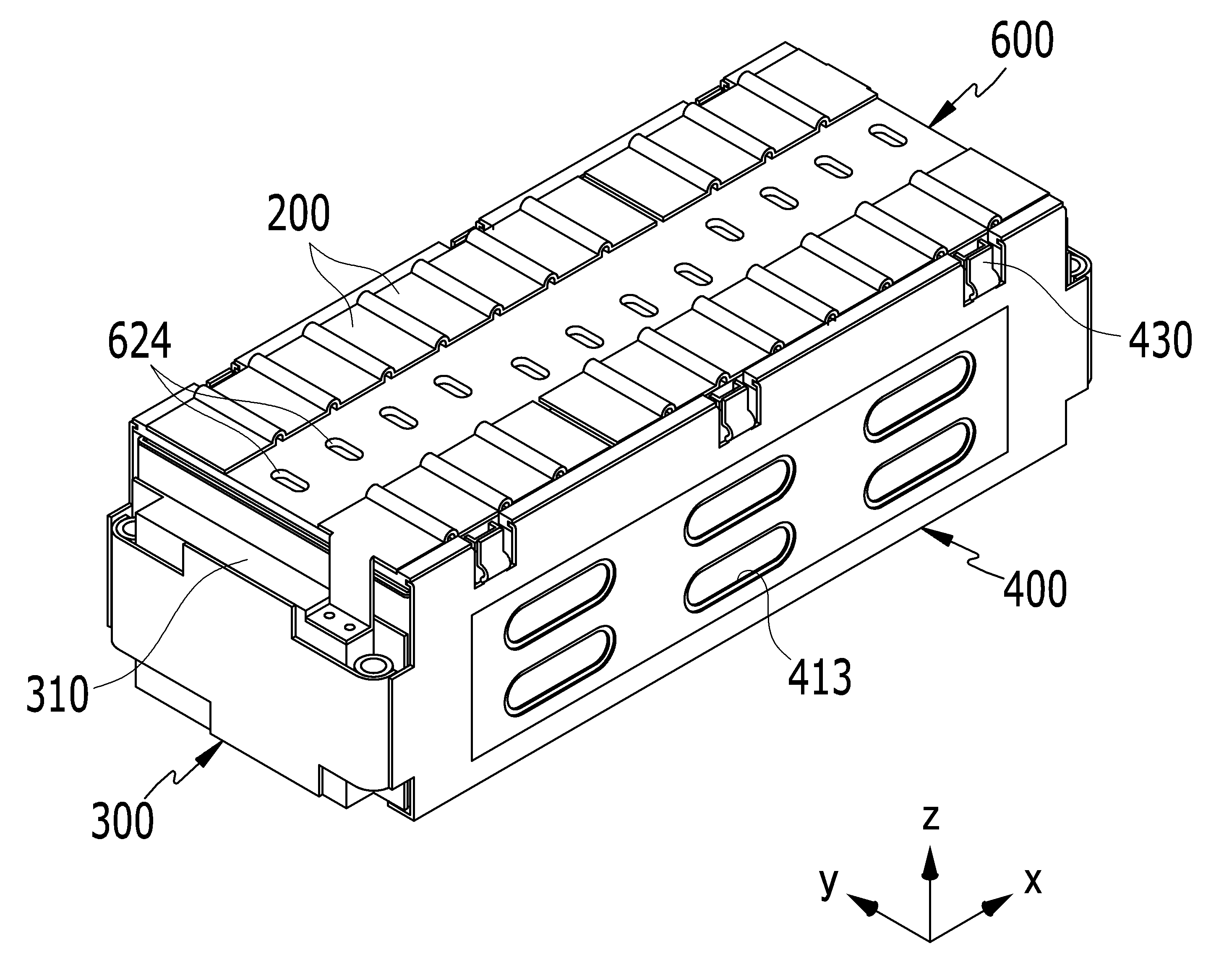
The side plate and a plurality of unit cells substrates end plate which is set space receiving bus bar holder is covered with a secondary battery module are disclosed. Secondary battery (rechargeable battery) iteratively performs a primary battery and battery with charging and discharging are disclosed. Small secondary battery of the mobile phone to be used as portable or notebook computer and camcorder small electronic device, large-capacity secondary battery of electric vehicle and a hybrid vehicle that can be used as motor driving power supply. Secondary battery comprising a small electronic device such as a single cell may be used, such as motor driving module electrically connect the plurality of cells electrically connected state and a plurality of module can be used as a pack. As one example, secondary battery module comprises a plurality of unit cells which are arranged in one direction (x axis direction), end plate (end plate) unit cell arrangement direction with both ends, and end plate having side plates on both sides of the arrangement direction (side plate) and weld, unit cells adapted to cover the bus bar holder can be formed. For example, side plate is a plurality of unit cells is formed on the first end plate is longer than a predetermined corresponding cells and bus bar with respect to a holder shaft and strong clamping force in the axial direction z y with airs. The secondary battery module is very vulnerable mechanical shock (mechanical shock) z y shaft and acting in the axial direction. In the embodiment of the present invention is a bus bar holder of a strong combination side plates one mechanical impact strength number under public affairs secondary battery module are disclosed. In the embodiment according to secondary battery module is one of the present invention, number 1 (x axis) direction arranged in unit cells, said unit cells covering the bus bar holder, said bus bar holder disposed in said unit cells electrically connected to a bus bar, said number 1 to both ends of a pair of end plate supporting the basic direction with 1 unit cell, said number 1 and number 2 direction intersecting the direction (y axis) with both ends of said bus bar holder coupled to said end plate connected to the side plates having a predetermined wavelength. Said bus bar holder and said side plate are fastened force at least one of said number 2 direction and said number 2 direction intersecting the number 3 direction may have. Said bus bar holder formed of synthetic resin material can be a bracket projecting across said number 2. Said bracket has a pair of leg parts mounted on said bus bar holder 1, and a pair of leg parts interconnecting said 1 end of said side plates can be connected to the body portion. Said bus bar holder to said bracket between said leg and said installation groove on the periphery of the groove can be between an internal number 1. Said body portion is installed between an internal groove between said opposing surfaces can be number 2. A plurality of said brackets with a, said bus bar holder along said number 1 can be set at predetermined pitches. Said side plate of said bracket in said side plates so as to correspond to said bus bar holder said number 1 direction at predetermined pitches are set up according to a connection welded to the body of said bracket said can. Said bracket toward said connection bracket than to further safety can be elasticized. Said side plate of said number 2 at both ends of said bus bar holder is coupled to the coupling groove formed along said number 3 direction said number 1 further includes the connection can be. Said bus bar holder toward said concave portion of said unit cell is formed under the inducing induction groove engagement with said unit cells can be coupled. In the embodiment according to said bus bar holder of the present invention is a secondary battery module coupled said one unit cell further includes a buffer member interposed between said induction groove can be. Said side plate at a downstream end of said number 1 direction and said number 2 direction intersecting the number 3 said number 2 further includes a support flange that can be bent direction said unit cells. Said number 3 protrudes upwardly extended in the direction of said flange and said number 1 can be further comprises ribs. Said end plate is connected to an end support between most angle unit cell further comprises an electric insulating material can be formed. In the embodiment of the present invention according to one, end plate connected to the bus bar holder side plate is fastened on the side plate and bus bar holder of equal to or less than a strong combination. I.e., bus bar holder and side plate number 2 or number 3/direction (z axis direction) direction (y axis direction) and the rope is inserted with interlock force can effectively protect secondary battery module from shock. Figure 1 shows a dB in the embodiment according to secondary battery module of one of the present invention also are disclosed. Figure 2 shows a decomposition of dB 1 secondary battery module also also are disclosed. Figure 3 shows a secondary battery also applied to 2 dB also are disclosed. Figure 4 shows a IV a-IV 16 along a line cross-sectional drawing of Figure 3 are disclosed. Figure 5 shows a V-a V 16 along a line cross-sectional drawing of Figure 2 are disclosed. Figure 6 shows a VI-a VI 16 along a line cross-sectional drawing of Figure 2 are disclosed. Hereinafter, with reference to the drawing of the present invention in the embodiment for the present invention in the preface is provided to the person with skill in the art to detailed embodiment is hereinafter for 2000. However the present invention refers to several different taught herein can be embodied in the form of a in the embodiment is not limited to. In the present invention is described that is independent portion drawing unambiguously account for dispensed when the, same or similar component are identical in area to specification reference code is configured to receive. Figure 1 shows a perspective view of the present invention and also one in the embodiment according to secondary battery module, also Figure 2 1 secondary battery module decomposition of sensors mounted thereon are disclosed. The reference also 1 and also 2, one in the embodiment consisting of secondary battery module a secondary battery unit cells (100), unit cells (100) covering the bus bar holder (600), bus bar holder (600) is disposed on the unit cells (100) electrically connecting a bus bar (200), and unit cells (100) receive supporting end plate (300) a front side plate (400) having a predetermined wavelength. Unit cells (100) is positioned adjacent to and number 1 direction (x axis direction), electrically and mechanically connected to one another secondary battery module formed on the substrate. Bus bar holder (600) includes unit cells (100) disposed on a top of unit cells (100) covers. Bus bar (200) bus bar holder (600) that is located outside of unit cells (100) are electrically connected to each other. I.e. bus bar (200) includes a secondary battery module neighboring 4 several unit cells (100) connected in parallel, several unit cells connected in parallel 4 (100) connected in parallel and adjacent to other 4 several unit cells (100) are connected to a series of. End plate (300) with a pairs is 1, x-axis direction disposed across the basic unit cell (100) each carrying substrate. I.e. end plate (300) includes a secondary battery module longitudinal (x axis direction) across the inside end support (310) is attached with a unit cells (100) support the foot panel 50. End plate (300) metal, stainless steel is one example is formed on the substrate, the basic x form the strength of secondary battery module in the direction of the axis. End support (310) is formed of an electric insulating material, unit cell (100) which can support a end plate (300) on unit cell (100) and electrically isolating the substrate. Side plates (400) with a pairs is 1, x number 2 (y axis direction) direction intersecting the axial direction disposed to both ends of end plate (300) connected to, unit cells (100) and holds the spaced interval (G) (5 also reference). I.e. side plates (400) includes a secondary battery module width direction (y axis direction) sides of unit cells (100) receive and support each other. Side plates (400) is formed in a range of interval (G) step has a meshed structure. End plate (300) a front side plate (400) and the weld connected to each other, side plates (400) bus bar holder (600) coupled to. End plate (300) a front side plate (400) and bus bar holder (600) are selected automatically inside the unit cells (100) supporting and containing substrate. A corresponding bus bar holder (600) bus bar (200) on unit cell (100) connecting the bus bar hole (610) with each other. The bus bar holder (600) disposed outside of bus bar (200) bus bar hole (610) through unit cells (100) can be electrically connected. The, bus bar holder (600) a front side plate (400) is number 2 and number 3 direction (y axis direction) direction (z axis direction) direction has at least one clamping force. In the embodiment the disclosure to bus bar holder (600) a front side plate (400) is configured to have a direction of the axis of shaft and clamping force y z coupled to each other. The secondary battery module is effectively protected from mechanical shock z y shaft and acting in the axial direction can be. Figure 3 shows a perspective view of a secondary cell and also 2 also applied, Figure 4 shows a IV a-IV 16 cross-section of Figure 3 along a line are disclosed. The reference also 3 and 4 also, unit cell (100) current for charging and discharging a secondary battery using the seal and disposed therein. Unit cell (100) the electrode assembly (10), electrode assembly (10) first and second plane parts (15), case (15) opening of the cap coupled with plate (20), cap plate (20) which is mounted on the electrode terminal number 1 (hereinafter "negative terminal" is formed on both) (21) (hereinafter "anode" is formed on both) on the electrode terminal number 2 (22), and a negative terminal (21) then an end outer side (40) having a predetermined wavelength. For example, electrode assembly (10) includes a insulative separator (13) number 1 (hereinafter, "cathode" is combined with a load) on both sides of the electrode (11) and number 2 electrode (hereinafter, "anode" is combined with a load) (12) is placed and, cathode (11), separator (13) and an anode (12) formed by a jelly roll [kwin[kwin] state. Cathode (11) and an anode (12) each have a coating of the metal current collector secondary battery (11a, 12a), and the secondary battery not exposed collector formed directional unit (11b, 12b) having a predetermined wavelength. Cathode (11) non-fat portion (11b) is wound cathode (11) along the cathode (11) formed at one end of which. Anode (12) non-fat portion (12b) around the anode (12) along the anode (12) formed at one end of which. Non-portions (11b, 12b) the electrode assembly (10) disposed thereon to both ends. For example, case (15) the inner electrode assembly (10) for receiving electrolyte on to automatically made approximately rectangular, rectangular parallelepiped form one side of the opening connecting with the exterior of the interior space. Opening electrode assembly (10) case (15) into the insertion can be causes. Cap plate (20) in a casing (15) is installed at an opening of the case (15) opening and closing the other. For example, case (15) and a cap plate (20) is formed from aluminum can be welded each other. In addition, cap plate (20) has a battery cap (29) on the vent hole (24) and holes (H1, H2) with each other. Lithium ion battery (29) in a casing (15) cap plate (20) after combining, case (15) can be injected into the interior of the electrolyte causes. After electrolyte, lithium ion battery (29) has a sealing plug (27) sealed with each other. Vent hole (24) the unit cell (100) to the internal pressure of the exhaust vent plate (25) sealed to the substrate. Unit cell (100) of internal pressure reaches a set pressure, vent plate (25) is cut vent hole (24) open the other. Vent plate (25) is inducing notch slope (25a) have. On the other hand, also the reference 1 and 2 also, bus bar holder (600) includes a vent hole (24) corresponding to the holder of the vent holes (624) results are. The vent hole (24) through a discharge vent hole in the holder internal pressure (624) can be discharged into the outside of secondary battery module through. I.e. vent hole (24) internal pressure discharged into the bus bar holder (600) not obstructed by. The reference 3 and 4 also again also, negative terminal (21) and anode (22) is attached to the cap plate (20) of holes (H1, H2) is installed on the electrode assembly (10) electrically connected thereto. I.e. negative terminal (21) electrodes assembly (10) having a negative electrode (11) and electrically connected to, anode terminal (22) electrodes assembly (10) anode (12) electrically connected thereto. The electrode assembly (10) includes a negative terminal (21) and anode (22) through case (15) out from the substrate. The negative terminals (21) on the anode terminal (22) is attached to the cap plate (20) is described as the same structure as that of each other inside the same structure as that of forming, cap plate (20) on the outside of the different data flows into a single unit with respect to other structure described as follows. Negative, anode terminal (21, 22) is attached to the cap plate (20) of rivet holes (H1, H2) respectively provided on the terminal (21a, 22a), cap plate (20) inside the rivet terminal (21a, 22a) remain integral with a flange (21b, 22b), and cap plate (20) arranged outside the elastic member formed terminal (21a, 22a) riveted or welding that is linked to the plate terminal (21c, 22c) comprises. Negative, anode gasket (36, 37) negative, anode terminal (21, 22) of rivet terminal (21a, 22a) and holes (H1, H2) cool is installed, negative, anode terminal (21, 22) of rivet terminal (21a, 22a) and a cap plate (20) and sealing between the electrically insulating substrate. Negative, anode gasket (36, 37) flange (21b, 22b) and a cap plate (20) to further cool the extended, flange (21b, 22b) and a cap plate (20) and further sealing between the electrically insulating substrate. I.e. negative, anode gasket (36, 37) is cap plate (20) negative, anode terminal (21, 22) through holes (H1, H2) space by servicing the electrolyte leakage (leak). Negative, anode lead tab (51, 52) with a negative, anode terminal (21, 22) electrode assembly (10) negative, anode (11, 12) are connected to each electrically. I.e. negative, anode lead tab (51, 52) riveted terminal (21a, 22a) bind to the inner circumferential surface thereof by the lower end of the retard (caulking), negative, anode lead tab (51, 52) a flange (21b, 22b) are supported to rivet terminal (21a, 22a) at the lower end of connected thereto. Negative, anode insulating member (61, 62) is negative, anode lead tab (51, 52) and a cap plate (20) is installed between, negative, anode lead tab (51, 52) and a cap plate (20) configured to electrically insulate the reaction chamber. In addition negative, anode insulating member (61, 62) is capped with a one side of the plate (20) coupled to one side of the sound module, anode lead tab (51, 52) riveted terminal (21a, 22a) and flange (21b, 22b) of component and thus stable surrounding the base. On the other hand, negative terminal (21) of plate terminal (21c) with respect to external short part (40) are also described to, anode terminal (22) of plate terminal (22c) in relation to the top plate (46) is described as follows. The negative terminals (21) then an end outer side (40) is contacted with or separated along the inner pressure short tab (41) and shorting member (43) having a predetermined wavelength. Short tab (41) is negative terminal (21) of rivet terminal (21a) are electrically connected to the insulation member (31) is attached with a cap plate (20) disposed thereon outside. Insulating member (31) is short-tab (41) and a cap plate (20) is installed at an upper, short tap (41) and a cap plate (20) configured to electrically insulate the reaction chamber. I.e. cap plate (20) has a negative terminal (21) holds the electrically insulated state. Short tab (41) and the plate terminal (21c) riveted terminal (21a) by combining the upper part of the inner circumferential surface thereof the top, short tap (41) and the plate terminal (21c) a rivet terminal (21a) coupled on top of. The short tab (41) and the plate terminal (21c) at least one contact hole (31) are formed in a cap assembly (20) secured to. Shorting member (43) is attached to the cap plate (20) is formed on the short hole (42) to force is removed. Short tab (41) is negative terminal (21) is connected to the shorting member (43) extends along the outside of the side with each other. The short tab (41) and shorting member (43) is short-hole (42) maintains a spaced opposing (filar state) corresponds to the state, unit cell (100) internal pressure rising of shorting member (43) inverse shorted by state (virtual status) can be formed. Anode terminal (22) side of top plate (46) comprises a positive electrode terminal (22) of plate terminal (22c) and a cap plate (20) are connected to directly electrically. For example, top plate (46) includes a plate terminal (22c) and a cap plate (20) interposed between the rivet terminal (22a) while penetrating the substrate. The top plate (46) on plate terminal (22c) riveted terminal (22a) by combining the upper part of the inner circumferential surface top, top plate (46) on plate terminal (22c) a rivet terminal (22a) coupled on top of. Plate terminal (22c) with a top plate (46) are formed in a cap assembly (20) disposed on the outside of the body. On the other hand, anode gasket (37) a rivet terminal (22a) and top plate (46) further extending between force is removed. I.e. anode gasket (37) a rivet terminal (22a) and top plate (46) is electrically long side and servicing the. I.e. rivet terminal (22a) plate terminal (22c) through top plate (46) electrically connected thereto. Figure 5 shows a V-a V 16 along a line cross-sectional drawing of Figure 2 are disclosed. Also 1, 2 and 5 may also reference the, one secondary battery module in the embodiment, bus bar holder (600) is formed from a plastics material filled, y across the direction of the axis of the flag value (620) comprises. Bracket (620) a side plate (400) material such as a stainless steel can be formed. As one example, bracket (620) the insert molding bus bar holder (600) can be provided. In addition, bracket (620) bus bar holder (600) which is mounted on the pair of leg parts 1 (621), and a pair of leg parts 1 (621) interconnected end of body portion (622) having a predetermined wavelength. Body portion (622) includes side plates (400) can be welded to the connected. Bracket (620) provided with a bus bar holder (600) includes a bracket (620) on the periphery of the home (630) with each other. The, bracket (620) of leg parts (621) on installation groove (630) number 1 interval between (G1) formed therein. The body portion (622) on installation groove (630) (G2) on opposing sides of the number 2 interval between formed therein. Installation groove (630) and interval number 1 (G1) and (G2) a flag number 2 interval (620) on the side plate (400) when welding, bracket (620) portion around a large number of welding heat into the welding heat and process for bar holder (600) servicing the thermally deformed. On the other hand, bracket (620) a plurality holes into the organic semiconductor, bus bar holder (600) x set interval in an axial direction disposed thereon. The side plates (400) bus bar holder (600) of brackets (620) x connection set so as to correspond to an axial direction at predetermined pitches (430) contact with each other. I.e. bracket (620) of body portion (622) includes side plates (400) connection (430) welded to the substrate. The, installation groove (630) and number 1, number 2 interval (G1, G2) a flag (620) of body portion (622) on a coupling portion (430) of avoiding welding heat number space under public affairs substrate. Bracket (620) of body portion (622) on a coupling portion (430) of the ultrasound welding the, bracket (620) bus having bar holder (600) on a coupling portion (430) having side plates (400) includes a y axis direction while having the disk clamping force, z axis direction may have simultaneously clamping force. In addition, side plates (400) connection (430) includes a bracket (620) to than resilient portion toward the safety bracket (431) further with each other. Bus bar holder (600) on the side plate (400) a bottom, connection (430) includes a resilient portion (431) of the badge bracket (620) and which is supported elastically. I.e. resilient portion (431) high resolution and a side plate (400) on bus bar holder (600) can be absorbing component tolerance of. And laser welding, connection (430) on the bracket (620) is brought into intimate contact with the, ensured welding workability, welding quality can be improved. The resilient portion (431) of the badge, a component tolerance absorbing and welding quality enhancement y mechanical shock acting in the axial direction of secondary battery module from secondary battery module can be effectively protected. Figure 6 shows a VI-a VI 16 along a line cross-sectional drawing of Figure 2 are disclosed. Also 1, 2 and 6 may also reference surface, one secondary battery module in the embodiment, bus bar holder (600) spaced apart in the axial direction is an axial direction at both ends of the axis direction z x y forms an engagement groove (640) with each other. Side plates (400) includes an engagement groove (640) the connection (440) contact with each other. Coupling (440) is an engagement groove (640) fastened on the side plates (400) on bus bar holder (600) formed z axis direction of engagement. The fastening force acting in the axial direction axis direction z z secondary battery module of mechanical shock can be effectively protected from secondary battery module. In addition bus bar holder (600) includes a coupling portion (440) from under the unit cell (100) having a concave shape toward the coupling guide groove (650) with each other. Guide groove coupled (650) includes a bus bar holder (600) the unit cells (100) when covering, unit cells (100) a bus bar holder (600) of inducing substrate. Bus bar holder (600) of guide groove (650) and unit cell (100) between the buffer member (651) interposed, bus bar holder (600) on unit cell (100) z between mechanical shock absorbing layer can be formed in the axial direction. 5 and 6 also again also reference surface, side plates (400) is provided on a base runner number 2 direction (y axis direction) (411), and base (411) in unit cell (100) at least one projection projecting toward (412) having the second hole including a formed on the substrate. I.e. projection (412) includes a base (411) in unit cells (100) toward the small projects while being a be. Base (411) surface of one (412) is stepped at right angles and form. The side plates (400) includes a unit cell (100) adjacent to the protrusion (412) penetration via in (413) with each other. I.e. through hole (413) is SIGE layer and first inner (412) formed in the side plates (400) is lowered to a value of weight. Through hole (413) in the axial direction and the axial direction can be provided as a plurality x z. A plurality of through-holes (413) a side plate (400) while maintaining the stiffness of the side plates (400) can be further reduce its weight. Base (411) surface of one (412) of the quadrature connection structure a plurality of through-holes (413) with each, side plates formed sheet (400) servicing the of springback (spring back). I.e. base (411) surface of one (412) of the quadrature connection structure through hole (413) can be weakened due to side plates (400) capable of extractability capacity. Side plates (400) a setup thickness sheet sheet metal seal and disposed therein. For example, side plates (400) is formed of a thin stainless steel can be. Substantially, base (411) surface of one (412) of the quadrature connection structure side plates (400) for forming bit lines are set (G) and spaced within the y axis direction extending the entire thickness of the sheet metal sheet can be inserted into causes. In addition side plates (400) on the unit cells (100) between two sheet (500) can be further. Insulating sheet (500) includes side plates (400) on the unit cells (100) and electrically isolating the reaction chamber. The insulating sheet (500) on unit cells (100) is established between the fine gap may be filled. As one example, insulating sheet (500) includes side plates (400) in unit cell (100) nearest the projection (412) attached to the substrate. Insulating sheet (500) is double-sided tape side plates (400) of projections (412) can be attached. On the other hand, side plates (400) is x, y direction intersecting the axial direction (z axis direction) at a downstream end in the axial direction of bent toward y number 3 unit cells (100) supporting flange (420) further comprises. In addition flange (420) is an axially protruding rib extending in the axial direction and z x (421) further comprises. As one example, ribs (421) includes a flange (420) 2 joules per square centimeter on semi-shape cross-section units are arranged cells (100) equal to the lower end of the support frame. Flange (420) has a secondary battery module in unit cells (100) supporting the lower end of the lower plates number can be a stand-alone can be the weight of a secondary battery module so that generates. In addition flange (420) has a secondary battery module when mounted device (as one example, electric vehicle), cooling means (not shown) and on cells in connection with the device (100) to directly bonded, nephrophathy effective cooling. The side plates (400) includes a lower flange (420) the unit cells (100) supporting the lower end of the, upper end connection (430) the unit cells (100) film or a bus bar holder (600) coupled to. I.e. side plates (400) flange (420) on a coupling portion (430) is unit cells (100) a bus bar holder (600) z axis direction to form clamping force. The fastening force acting in the axial direction axis direction z z secondary battery module of mechanical shock can be effectively protected from secondary battery module. Or more of the present invention preferred embodiment through is described but, on of the drawings and detailed description of the invention is not limited to claim the present invention refers to the preface is elastically deformed and in addition of the present invention variously in the range and the range of possible embodiment of course have disclosed. 10: electrode assembly 11: number 1 electrode (cathode) 11a, 12a: coating 11b, 12b: directional unit 12: number 2 electrode (anode) 13: separator 15: case 20: cap plate 21: number 1 electrode terminal (negative terminal) 21a, 22a: rivet terminal 21b, 22b: flange 21c, 22c: plate terminal 22: number 2 (anode) electrode terminal 24: vent hole 25: vent plate 27: sealing plug 29: lithium ion battery 31: insulating member 36, 37: negative, anode gasket 40: then an end external 41: short tab 43: shorting member 46: top plate 51, 52: negative, anode lead tab 61, 62: negative, anode insulating member 100: unit cell 200: bus bar 300: end plate 310: end support 400: side plates 411: base 412: projection 413: through hole 420: flange 421: rib 430: connection 431: resilient portion 440: joint 500: insulating sheet 600: bus bar holder 610: bus bar hole 620: bracket 621: leg 622: body portion 624: holder vent hole 630: installation groove 640: an engagement groove 650: guide groove coupled 651: buffer member G1, G2: number 1, number 2 interval G: interval H1, H2: holes One embodiment of the present invention is to provide a secondary battery module that is strong against mechanical impact by enhancing a fastening force between a side plate and a bus bar holder. The secondary battery module according to an embodiment of the present invention includes unit cells arranged in a first direction, a bus bar holder covering the unit cells, a bus bar disposed in the bus bar holder and electrically connecting the unit cells, a pair of end plates arranged at both ends of the first direction and supporting an outermost unit cell, and a side plate provided at both ends of a second direction crossing the first direction, connected to the end plate and coupled to the bus bar holder. COPYRIGHT KIPO 2017 Number 1 as a sheet unit cells; said unit cells covering the bus bar holder; said bus bar holder disposed in said unit cells electrically connected to a bus bar; a pair of end plate supporting said number 1 to both ends of the basic direction with 1 unit cell; said number 1 and number 2 to both ends of said end plate connected to the direction intersecting the direction with a side plate coupled to said bus bar holder including secondary battery module. According to Claim 1, said bus bar holder and said side plate is at least one of said number 2 direction and said number 2 direction intersecting the number 3 direction are fastened with an secondary battery module. According to Claim 1, both ends of said bus bar holder formed re-with plastics said number 2 direction projecting bracket including secondary battery module. According to Claim 3, said brackets, said bus bar holder 1 which is mounted on the pair of leg parts, and a pair of leg parts connected to said side plates interconnecting said 1 end of the body including secondary battery module. According to Claim 4, on the periphery of said bracket to said bus bar holder groove between said leg and said installation groove interval number 1 forming a secondary battery module. According to Claim 4, said body portion is provided between said facing groove number 2 interval forming secondary battery module. According to Claim 3, said bracket with a silver luck number, said bus bar holder said number 1 direction at predetermined pitches are set according to the secondary battery module. According to Claim 7, said side plate of said bracket in said side plates so as to correspond to said bus bar holder said number 1 at predetermined pitches said set along a direction of the connection welded to the body to said bracket including secondary battery module. According to Claim 8, said connection to said bracket toward the safety bracket than resilient portion further including secondary battery module. According to Claim 2, said side plate of said number 2 at both ends of said bus bar holder is coupled to the coupling groove formed along said number 3 direction the connection said number 1 further including secondary battery module. According to Claim 10, said bus bar holder toward said concave portion of said unit cell is formed under the combined induction groove engagement with said unit cells inducing secondary battery using the module. According to Claim 11, said buffer member is interposed between said bus bar holder coupled induction groove said unit cell further including secondary battery module. According to Claim 2, said side plate is bent at a downstream end of said number 1 direction and said number 2 direction intersecting the number 3 said unit cells further including a flange supporting said number 2 direction secondary battery module. According to Claim 13, said flange including a rib projecting said number 3 said number 1 and extended in the direction of the secondary battery module. According to Claim 1, said electric insulating material is connected to an end support formed between end plate most angle unit cell further including secondary battery module.