DISPLAY DEVICE
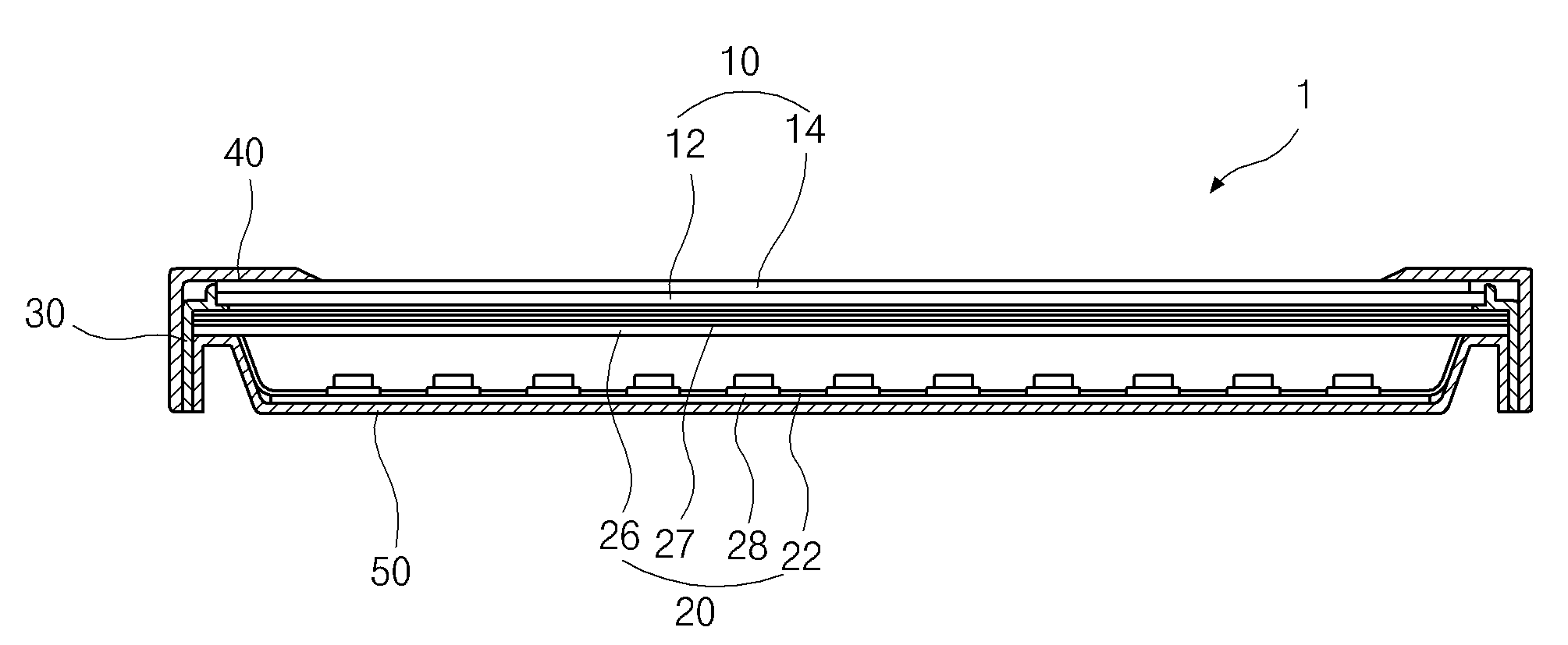
The present invention refers to display device relates to, a display device including a liquid crystal display device in particular [...] are disclosed. Recent development of information technology and information along with a mobile phone such as visually displays the display device made in the development of the user and, display device includes a display and other external factor having molecular sport non-emitting display an Image classification is coming in now. Non-light-emitting type display include liquid crystal display device is cited as an example (Liquid Crystal Display, multi-hereinafter LCD). Wherein, LCD requires a self light-emitting elements is equal to a memory not have since additional light source. The, rear view light source backlight unit (Backlight unit) is provided toward the front LCD is irradiated with light this is effected by insuring only identifiable embodied in the picture. A cold-cathode fluorescent lamp light guide panel has the (Cold Cathode Fluorescent Lamp: CCFL), external electrode fluorescent lamp (External Electrode Fluorescent Lamp), light-emitting diode (Light Emitting Diode: LED, a multi-hereinafter LED) etc.. In particular is performed, LED is small, low power consumption, high reliability as well as widely as a light source for display such as disclosed which has characteristics of being are disclosed. The sidelight-type (side light type) and direct light type backlight unit structure for arranging the lamp according (direct light type) which is divided into, a sidelight type one or a pair of lamp have a triangle shape disposed in the structure, which has a light guide plate disposed in each two or two pairs of lamp on both sides, direct light type with several optical sheet arranged below the connector has the structure. Recently, consumer upon demand by the liquid crystal display device than the aluminum in the present study the resultant structure, the resultant structure from an edge light type surface light box shape more suitable for liquid crystal display device. Figure 1 shows a cross-section of a direct light type LCD also LED emits are disclosed. As shown, LCD (1) includes a number 1 and number 2 substrate (12, 14) is connected to the liquid crystal panel (10) and to the rear of a backlight unit (20) is combined with each other. Wherein, backlight unit (20) includes a reflective plate (22) which, on the upper surface of a plurality of LED (28) arranged moves, these LED (28) is provided at the upper diffuser plate (26) and a plurality of optical sheet (27) is the lungs. The, adjacent 2 to 3 of LED (28) is mixed and then overlapping and mutually oriented so that radiation emitted from the liquid crystal panel (10) is equal to cf [...] incident number. Such LED (28) including a backlight unit (20) the LCD panel (10) stop the casing (40) and guide panel (30) and cover [...] (50) module through which i.e., liquid crystal panel (10) and backlight unit (20) such as edge of rectangular shaped guide panel (30) around the liquid crystal panel (10) top front edge around the stop (40) and backlight unit (20) through the rear view [...] (50) are joined in a fore-and-aft each fume guide panel (30) is further integrated with each other. On the other hand, recent such LCD (1) comprises a portable computer as well as desktop computer monitor and wall type television such as its use region with the gate during driving is gradually wide, while having a wide display area for reducing the amount of weight and volume than the aluminum block is not etc.. In addition, LCD (1) in addition to a light and thin display area includes a display area of a bezel (bezel) region is widely and display region other than small as possible forming narrow hemp cloth gel etc. (narrow bezel) is also required. However, general LCD (1) is difficult to implement the diaphragm to various [...] number point of the doors, one of the backlight unit (20) light source is a LED (28) generated from the liquid crystal panel (10) and that of the first edge to the of, which consequently narrow hemp cloth gel inhibiting implementation to be coated. I.e., it is a point light source LED (28) having a predetermined direction angle [...] light emitted from liquid crystal panels (10) where it is incident, a liquid crystal panel (10) include LED (28) light emitted from the liquid crystal panel not ball number square ([...]) (10) present in the same edge of hypermetropia. The liquid crystal panel (10) for 24 hrs implementing [...] to mask edge of square ([...]) are disclosed. In particular, recent large-scaled (approximately 100 inches) such as one Image and video wall (video wall) for implementing a, plurality of LCD (1) in the form of a multiple-panel display device in combination with the so-called "Tiled" (multi-a panel display device) which studies of aluminum, in the case of a plurality of LCD multi-panel display device (1) is equal to continuity of each bezel Image linearly by the lowering. The, implementing a multi-panel display device also having [...] than LCD (1) kneading step requiring are disclosed. The present invention refers to said number for the fixing and hydrogen gas, intended to implement [...] LCD having a number 1. In addition, the multi-panel display device is not lowered Image continuity [...] intended for a number number 2. As in order to achieve the aforementioned purposes, the present invention refers to LCD panel, positioned in said edges, a plurality of number 1 LED including number 1 LED assembly and diffusing plate, the optical sheet including the light guide plate, said liquid crystal panel and said backlight unit around the edges of a rectangular frame shape, fits into the vertical portion and projecting to the storehouse guide including guide panel and said vertical, storehouse guide positioned in said lower, including number 2 LED assembly and a plurality of number 2 LED, said backlight unit and said liquid crystal display device including a liquid crystal panel cover the outer [...] including number 1, said number 2 LED assembly supplies the emitted light includes said storehouse guide after focal point, said ball number at the edge of the display device along a liquid crystal panel light assembly is a number [...] substrate. As mentioned above, the present invention back light unit around the edge of the liquid crystal panel in accordance with a guide panel more storehouse guide, lower storehouse guide number 2 LED backlight unit the auxiliary light sources is located more assembly, permanent vice versa can be uniformly supplying light to a liquid crystal panel, liquid crystal panel bezel region can be a display area of the dielectric layer, a liquid crystal display device can be [...][...] number equal to or less than. In addition, a multiple-panel display device in the Image plane in a liquid crystal display device disconnected [...] minimize delamination occurs can be equal to or less than. Figure 1 shows a cross-section of the filter is also LED using direct light type LCD. Figure 2 shows a decomposition of the present invention number 1 in the embodiment according to LCD also shown to determine sensors mounted thereon. 3A is also shown in perspective view of the present invention number 1 in the embodiment according to guide panel determine. Also shown is also 3b 3a cross-section determine the cross-sectional drawing. 4A - 4b portion of Figure 2 is also shown in cross-section determine the modular cross-sectional drawing. 5A - 5c is to determine the structure of the present invention number 1 in the embodiment according to guide panel various storehouse guide also shown in perspective view. Figure 6 shows a multi-panel display device of the present invention number 2 in the embodiment according to cross-section portion of coarse also shown cross-sectional. Figure 7 shows a fiber optical member also including Image through the disconnected configuration determine the developing compensation shown schematic. 8A - 8b also includes a bezel according to viewers for cognitive effect photograph. Hereinafter, the present invention according to in the embodiment detailed with reference to a drawing as follows. - Number 1 in the embodiment - Figure 2 shows a of the present invention number 1 in the embodiment according to LCD shown sensors mounted thereon to determine degradation also are disclosed. As shown, of the present invention number 1 in the embodiment according to LCD (100) comprises a liquid crystal panel (110) and backlight unit (120), and liquid-crystal panel (110) and backlight unit (120) for module casing stop (140), guide panel (200) and cover [...] (150) consists of the. The, descriptions for facilitating the travel direction on the drawing, liquid crystal panel (110) toward the front surface prior to a backlight unit of that number (120) a liquid-crystal panel (110) is disposed rearwardly of and, their outer rectangular frame-shaped guide panel (200) around the liquid crystal panel (110) is provided in front of the stop casing (140) is located the backlight unit (120) rear view of covered [...] (150) located within the, front and rear are combined and integrated with each other. More specifically these sequences to each heat. First liquid crystal panel (110) is responsible for the Image presentation that cannot role as part, liquid crystal layer (not shown) facing each other on both sides of the number 1 and number 2 substrate coalesced (112, 114) comprises. The, active matrix multiplies the number represented in the although unambiguously on but before drawing, lower substrate array substrate is referred to as a conventional substrate number 1 (112) a plurality of gate line except the inner surface of the data line (pixel) is being defined, each thin film transistor (Thin Film Transistor: TFT) each intersection with a transparent pixel electrode formed in each pixel is provided in a one-to-one connected in the nanometer range. The upper substrate or color filter substrate is referred to as number 2 substrate (114) is provided corresponding to the inner surface of each pixel (R) example, rust (G), blue (B) color filter (color filter) and each gate line and color around a non a marking element to shade off the black matrix (black matrix) and thin film transistor is combined with each other. In addition, a transparent common electrode layer 17. have. Such liquid crystal panel (110) such as the flexible circuit substrate along at least one edge member (116) via a printed circuit board (117) module connected among the selected cover [...] (150) to the embarrassing rear view of contact with each other. Although not clear so although drawing appears on liquid crystal panel (110) of two substrates (112, 114) and a liquid crystal layer (not shown) on directions of orientation determining initial molecules inside, lower alignment film (not shown) interposed, (not shown) filled with a liquid crystal layer therebetween to prevent leakage of the substrates (112, 114) along an edge of [ssil pattern (seal pattern) formed therein. The, number 1 and number 2 substrate (112, 114) provided on the outer surface of each, lower polarizing plate (119b, 119a, also 4a reference) attached thereto. And liquid-crystal panel (110) indicates a difference outside rear view of a backlight unit supplying light transmittance is expressed (120) is combined with each other. Backlight unit (120) a liquid-crystal panel (110) located rear view of number 1 LED assembly (128) on, reflector (125), LED assembly (128) into the top of the LED assembly (128) on the guide support (127) spaced apart from the through to the holding plate (123) and diffuser plate (123) positioned in upper optical sheet (121) having a predetermined wavelength. Number 1 LED assembly (128) the back-light unit (120) as main won of, cover [...] (150) surface of (151) of inter-nested plate (plate) of number 1 PCB (128b) on number 1 PCB (128b) spaced apart from the mounting on a plurality of number 1 LED (128a) without using a tool. The, plurality of number 1 LED (128a) for a light-emitting efficiency and brightness enhancement, excellent light emitting blue LED chip including blue LED (128a) using, phosphor as' containing garnet (YAG: Ce) cerium doped yttrium aluminum ', i.e. yellow phosphor consisting of an LED (128a) being used disclosed. This, number 1 LED (128a) emitted from the blue light emitted by the phosphor mixed with yellow lights emitted from a light source by a fluorescent substance, a diffusion plate (123) toward the inventive white-to be coated. And, reflector (125) includes a plurality of number 1 LED (128a) can pass through the plurality of through hole (125a) is constructed a plurality of number 1 LED (128a) [...] number a number 1 PCB (128b) on [...] cover (150) surface of (151) covers the whole go to, a plurality of number 1 LED (128a) directed toward rear view of light plate (123) by light source towards the base. Reflector (125) through holes (125a) exposed through the plurality of number 1 LED (128a) upper plurality of number 1 LED (128a) to the luminance of a uniformity of the diffusion plate (123) and optical sheet (121) is the lungs. Wherein, a diffusion plate (123) and optical sheet (121) guide support (127) through supported sagging is prevented, optical sheet (121) includes a diffusion sheet and at least one condensing sheet which, a diffusion plate (123) and second light passing through the liquid crystal panel or (110) uniformly roast and cotton illuminant incident photon beam to reach the substrate. The, number 1 LED assembly (128) plurality of number 1 LED (128a) from the emitted light includes a diffusion plate (123) and optical sheet (121) and a high-grade light after being uniform in turn passing of the liquid crystal panel (110) in which, and a liquid crystal panel using (110) fluorescent Image display parts to be coated. The liquid crystal panel (110) and backlight unit (120) stop the casing (140), guide panel (200) and cover [...] (150) through a modular with substrate. Casing stop (140) a liquid-crystal panel (110) such as "V" shape cross-section so as to cover the upper and lateral sides of upper edge form square, liquid crystal panel (110) covering the side face of number 1 edge (141) number 1 on edge (141) perpendicularly from the liquid crystal panel (110) covering the upper surface of edge of number 2 (143) consisting of an. This casing stop (140) comprises a front face opened upper liquid crystal panel (110) implemented in consists of display an Image. Guide panel (200) further comprises a quadrangular frame shape, liquid crystal panel (110) and diffusion plate (123) and optical sheet (121) rear view of a liquid crystal panel support edge (110) and backlight unit (120) without resolution the position of, number 1 LED assembly (128) on side walls plate (123) (optical gap) or air gap (air gap) between the optical gap is equal to maintain. I.e., of the present invention number 1 in the embodiment according to direct light type backlight unit (120) is number 1 LED assembly (128) on side walls plate (123) at a certain distance between optical gap must be shaped such that it has an air gap (hereinafter, a multi-optical gap), optical gap is number 1 LED assembly (128) plurality of number 1 LED (128a) light emitted from the color being mixed, space, a plurality of number 1 LED (128a) uniformly light emitted from color being mixed, to diffusers (123) or an incident, or multiple number 1 LED (128a) generated from the high-temperature heat diffused by the plate (123) serves to prevent thermally generated to be coated. To implement such optical gap guide panel (200) is number 1 LED assembly (128) on side walls plate (123) for maintaining a spacing between the vertical portion (210) which, vertical portion (210) project from the inner side to the diffusion plate (123) and optical sheet (121) rear view of supporting storehouse guide edge (220) having a predetermined wavelength. Storehouse guide (220) includes a vertical portion (210) projecting vertically from horizontal plane (221, also 3a reference) which, liquid crystal panel (110) double-sided adhesive pad (not shown) such as tapes through the vertical portion (210) the upper surface of the attachment and fixed, a diffusion plate (123) and optical sheet (121) is rear view storehouse guide edges (220) in the plane (221) seated on and supported, number 1 LED assembly (128) on side walls plate (123) is equal to optical between stores. In particular, the storehouse guide of the present invention number 1 in the embodiment (220) into the bottom of the number 2 LED assembly (129) is further positioned, number 2 LED assembly (129) the back-light unit (120) of the light beam, a plurality of number 2 LED (129a) on, a plurality of number 2 LED (129a) at an mounted bar (bar) diametrically of PCB (129b) without using a tool. The, plurality of number 2 LED (129a) for a light-emitting efficiency and brightness enhancement, excellent light emitting blue LED chip including blue LED (129a) using, phosphor as' containing garnet (YAG: Ce) cerium doped yttrium aluminum ', i.e. yellow phosphor consisting of an LED (129a) being used disclosed. Such, a plurality of number 2 LED (129a) emitted from the blue light emitted by the phosphor mixed with yellow lights emitted from a light source by a fluorescent substance, storehouse guide (220) is equal to the inventive white-toward. I.e., a plurality of number 2 LED (129a) from the emitted light includes storehouse guide (220) enter into, storehouse guide (220) by storehouse guide within several times of total reflection surfaces (220) while in progress, liquid crystal panel (110) is equal to the edge of light [...] number. Through, of the present invention number 1 in the embodiment according to LCD (100) comprises a liquid crystal panel (110) of the permanent magnet vice versa it makes receive, ball number uniformly light, liquid crystal panel (110) peak of guide to be coated. The, liquid crystal panel (110) non-display area of the display area includes a bezel region is wider display area other than the dielectric layer can be, [...] LCD (100) can be implementing. More specifically later herein relative to you. In addition, liquid crystal panel (110) and backlight unit (120) rests the LCD (100) of the implement assembly cover [...] basis (150) plates (plate) shape surface of (151) and, the (151) vertical arranged at upper side (153) connected to the chamber. These guide panel (200) [...] cover (150) and casing stop (140) a liquid-crystal panel (10) and backlight unit (120) edge of the guide panel (200) kept in the liquid crystal panel (110) on top upper surface around the stop (140) and backlight unit (120) through the rear view [...] (150) are combined and each rear guide panel (200) integrally via modular substrate. The, casing stop (140) and the detection beam or tower case also bind potassium channels, guide panel (200) main support or main support, as bind potassium channels wherein the sheets, cover [...] (150) as the bottom cover or lower cover bind potassium channels also other. The LCD of the above-described structure (100) is required overlapped and recent lightweight LCD (100) for implementing, casing stop (140) the surfaces can be number. Casing stop (140) number and back through the LCD (100) can be of lightweight and pak style, effect can simplify the process. In addition, top stop is made of a metal material (140) due to the number of surfaces, process costs disapproval. Of the present invention number 1 in the embodiment according to LCD (100) guide panel (200) to storehouse guide (220) having, storehouse guide (220) into the bottom of the auxiliary light sources is number 2 LED assembly (129) further by placing, liquid crystal panel (110) can be edge to the of uniformly supplying light. Through, liquid crystal panel (110) of uniformly supplying light to a permanent magnet can be vice versa, liquid crystal panel (110) non-display area of the display area includes a bezel region is wider display area other than the dielectric layer can be, [...] LCD (100) can be implementing. The perspective view of the present invention number 1 in the embodiment according to guide panel shown determine which also 3a, 3b 3a cross-section determine the cross-sectional drawing is also shown also are disclosed. As shown, guide panel (200) further comprises a quadrangular frame shape which, having a predetermined thickness on the bottom (210a) including a vertical portion (210) on, vertical portion (210) projecting from the inside of the storehouse guide (220) having a predetermined wavelength. Wherein, guide panel (200) for vertical unit of (210) is the cover and mold of synthetic resin such as polycarbonate (polycarbonate), vertical portion (210) projecting inwardly into the storehouse guide (220) according to one of the permeable material is acrylic transparent resin such as polymethyl methacrylates (polymethylmethacrylate: PMMA) plastic (plastic) material or polycarbonate (polycarbonate: PC) sequence to a selected one of the number can be small, transparency, weather, when it passes through the light diffusion light is excellent in inducing preferably using PMMA. Storehouse guide (220) includes a vertical portion (210) from the inside of the vertical portion (210) projecting perpendicular to the plane (221) and a horizontal surface (221) angularly from the edge portion of one of the upper surface of obtuse-angled vertical portion (210) surface of (210b) facing away from the lower face (225) of the centrally located inclined slope constant number 1 (223) comprises. And, horizontal plane (221) number 1 extended from an edge of the lower surface of the inclined surface (223) and opposite number 2 slope (227) to including a, slope number 2 (227) the horizontal plane (221) from a lower surface (225) of the centrally located inclined toward number 1 (223) and is inclined such that consists of. The, slope number 1 (223) slope and number 2 (227) each have a lower surface (225) and both side edges of the connected thereto. The, guide panel (200) vertical portion (210) number 2 the inner inclined surface (227) defined between the inner space (A), number 2 LED assembly is positioned in its inner space (A) integrator (of Figure 2 129) to be coated. The, storehouse guide (220) number 2 is inclined surface (227) and lower surface (225) into the form of a slot-type [chaym it ladles, the father away from the portion (chamfer part: 229), [chaym it ladles, the father (229) to a horizontal (221) parallel to the surface (229a) comprising, vertical portion (210) number 2 the inner inclined surface (227) (A) (of Figure 2 129) between the inner space of the number 2 LED assembly includes a plurality of number 2 LED (of Figure 2 129a) is located at surface (229a) positioned facing to be coated. And, storehouse guide (220) which both ends include a longitudinal direction of the lower surface (225) which protrude from the rear hook shaped hook (228) is combined with each other. The, storehouse guide (220) slope of number 2 (227) (not shown) for supplying a specific shape pattern is uniform cf can be. Wherein, the storehouse guide (not shown) pattern (220) focal point for the light, elliptical pattern (elliptical pattern), polygonal pattern (polygon pattern), such as hologram pattern (hologram pattern) can be configured, the storehouse guide such pattern (not shown) (220) slope of number 2 (227) can be configured in such a way on printing or injection. The, of the present invention number 1 in the embodiment according to guide panel (200) vertical portion (210) to guide light to the inside of can be storehouse guide (220) further having, storehouse guide (220) into the bottom of the auxiliary light sources is number 2 LED assembly (129) further by placing, liquid crystal panel (110) can be edge to the of uniformly supplying light. More specifically refers to the relative heat also 4a - 4b to you. 4A - 4b is shown in cross-section determine the cross-sectional drawing part of Figure 2 for module also are disclosed. As shown, plate (plate) of number 1 PCB (128b) on number 1 PCB (128b) to the upper number 1 LED (128a) mounted number 1 LED assembly (128) on, number 1 LED assembly (128) plurality of number 1 LED (128a) opposite only (125a) exposed through the recessed shape (125) and the number 1 LED assembly (128) diffusion plate (123) and optical sheet (121) for leveling of the backlight unit (of Figure 2 120) are stacked with each other. Number 1 and number 2 (of Figure 2 120) on top of these backlight unit substrate (112, 114) and a liquid crystal layer (not shown) interposed between the liquid crystal panel (110) is located, number 1 number 2 substrate (112, 114) is provided between a pair of a particular light selectively transmitted through the polarizing plate (119a, 119b) attached thereto. The LCD panel backlight unit (of Figure 2 120) (110) [...] cover (150), guide panel (200) and casing stop (140) through a modular with substrate. More specifically relative residual, cover [...] (150) surface of (151) on number 1 LED assembly (128) which is loaded on, through hole (125a) through number 1 LED assembly (128) into the top of the number 1 LED assembly (128) plurality of number 1 LED (128a) only to expose the reflector (125) located therein. And, number 1 LED assembly (128) of inner faces of diffusers (123) are positioned diametrically constant interval, the diffuser plate (123) guide support (127) supported through, a diffusion plate (123) of inner faces of optical sheet (121) to be coated is located. This number 1 LED assembly (128) on side walls plate (123) and optical sheet (121) (of Figure 2 120) a backlight unit including the guide panel (200) by running edges where it is, guide panel (200) of storehouse guide (220) on a horizontal surface (221) of the diffuser plate (123) and optical sheet (121) and which is supported for digital edges of rear view. The optical sheet (121) faces of guide panel (200) for vertical unit of (210) the upper surface of (210a) edge part is supported by rear view LCD panel (110) to be coated is located. Wherein, a diffusion plate (123) and optical sheet (121) rear view of edge guide panel (200) on a horizontal surface (221) seated on and supported by, a diffusion plate (123) and number 1 LED assembly (128) plurality of number 1 LED (128a) guide panel (200) and guide support (127) spaced apart from the gas outlet is connected through, optical stores to be coated. And, liquid crystal panel (110) of stop faces of casing (140) liquid crystal panel (110) of the top and side edges and around the, casing stop (140) edge of number 1 (141) inside surface of guide panel (200) for vertical unit of (210) is firmly attached to the housed of, casing stop (140) and guide panel (200) a thermal dissipation structure and fastening to be coated. In addition guide panel (200) for vertical unit of (210) inside surface of cover [...] (150) side (153) is firmly attached to the housed of, guide panel (200) [...] cover (150) in addition to be assembled together by the fastening, casing stop (140) and guide panel (200) and cover [...] (150) a thermal dissipation structure and fastening to be coated. Thus, the LCD panel (of Figure 2 120) backlight unit (110) [...] cover (150), guide panel (200) and casing stop (140) through a modular with hypermetropia. Wherein, is included as a light source of the present invention number 1 in the embodiment according to LCD (of Figure 2 100) number 2 LED assembly (129) to further including, number 2 LED assembly (129) guide panel (200) of storehouse guide (220) of, more particularly to a guide panel (200) for vertical unit of (210) the inner storehouse guide (220) slope of number 2 (227) located between the inner space of the (A) to be coated. To a part of the internal space (A) number 2 LED assembly (129) includes a plurality of number 2 LED (129a) is storehouse guide (220) with [chaym it ladles, the father (229) arcuately (229a) and located so as to face, storehouse guide (220) is equal to incident light to the interior. Storehouse guide (220) focal point thereof a plurality of number 2 LED (129a) from the emitted light includes storehouse guide (220) by storehouse guide within several times of total reflection surfaces (220) while in progress, storehouse guide (220) to the outside of surface light source is supplied to emit light to be coated. The, storehouse guide (220) number 2 is inclined surface (227) (not shown) by a light pattern having light, storehouse guide (220) focal point storehouse guide light (220) in the plane (221) number 1 and slope (223) is machined through the arranged between outgoing therefrom. The, slope number 1 (223) implemented via the cotton illuminant number 1 LED assembly (128) plurality of number 1 LED (128a) emitted from the blended with, a diffusion plate (123) and optical sheet (121) through the LCD panel uniformly processing (110) has an supplied, horizontal plane (221) cotton illuminant implemented via the horizontal plane (221) seated on a diffusion plate (123) and optical sheet (121) edge of the machined uniform through the liquid crystal panel (110) at the edge of supply to be coated. The, (of Figure 2 100) of the present invention number 1 in the embodiment according to LCD comprises a liquid crystal panel (110) to the number more than light [...] angle are attached, in particular liquid crystal panel (110) also edge of light signals to a liquid crystal panel in accordance [...] number (110) across can guide the former. Through, (of Figure 2 100) of the present invention number 1 in the embodiment according to LCD comprises a liquid crystal panel (110) display area of the dielectric layer can be a bezel area, LCD can be implementing [...] (of Figure 2 100). On the other hand, number 1 and number 2 LED assembly (128, 129) a plurality of number 1 and number 2 LED (128a, 129a) is used as a temperature of a light emitting element over time and, a plurality of number 1 and number 2 LED such temperature rise (128a, 129a) of organic involving night and not joined together. Thus, a plurality of number 1 and number 2 LED (128a, 129a) light source of a backlight unit (of Figure 2 120) a predetermined one of the number 1 and number 2 LED most consonant and to be matters (128a, 129a) according to a temperature rise in the heat (heat dissipation) design are disclosed. Wherein, cover [...] (150) surface of (151) of inter-nested the number 1 LED assembly (128) is L-[...] cover (150) is wide (151) through number 1 LED assembly (128) plurality of number 1 LED (128a) to high-temperature heat generated from effectively can be emitted to the outside. However, number 1 LED assembly (128) is equipped with a small area on degrees of number 2 LED assembly (129) includes a plurality of number 2 LED (129a) located for high-temperature heat generated from, number 2 LED assembly (129) into the bottom of the LED housing (230) having further preferably. LED housing (230) is number 2 LED assembly (129) is loaded on the bar (bar) shaped to a highly heat-conductive metal material, with an edge part include number 2 LED assembly (129) settled storehouse guide (220) arcuately (229a) and located so as to face, a side edge a plurality of radiation fin (235) water to a heat sink (heat sink) type combustion chamber. A plurality of heat fins (235) by a number 2 LED (129a) high-temperature heat generated from the LED housing (230) is equal to emit through a quicker and more efficiently. The, as also shown in the 4a, LED housing (230) at the beginning and end of guide panel (200) of storehouse guide (220) with hook (228) fastened on only the chin (233) can be with. LED housing (230) of only the chin (233) to storehouse guide (220) of hook (228) by said coupling, of the present invention number 1 in the embodiment according to guide panel (200) is storehouse guide (220) arcuately (229a) and number 2 LED assembly (129) plurality of number 2 LED (129a) capable of maintaining optical gap between. In addition, a plurality of number 2 LED (129a) by high-temperature heat generated from such as PMMA or polycarbonate plastic material is generally composed guide panel (200) of storehouse guide (220) for cooling a piston occurring can be minimize. In addition, as also shown in the 4b LED housing (230) and a groove (231) having grooves (231) into only the chin (233) with, storehouse guide (220) of hook (228) in the recess (231) inserted to fit the hook (228) is only the chin (233) to be fastened to the, storehouse guide (220) on LED housing (230) configured to be more rigidly fastening the disapproval. The, storehouse guide (220) of hook (228) includes a vertical portion (210) (A) may be protruding from the internal space toward, or guide panel (200) may be formed projecting radially more outward, such as 4a also LED housing (230) and a groove (231) if not with is provided with hook (228) (A) projecting in an interior space formed by forming, LED housing (230) the guide panel (200) located only (A) formed along the inner space of the disapproval. 5A - 5c is also shown in the perspective view of the present invention number 1 in the embodiment according to guide panel to determine various storehouse guide structure are disclosed. As also shown in the 5a, guide panel (200) consisting of mold material vertical portion (210) from the inside of plastic material such as PMMA or polycarbonate is generally composed storehouse guide (220) with which projecting, storehouse guide (220) to a horizontal (221) and, horizontal plane (221) in parallel with a lower surface (225) and number 1 and number 2 slope (223, 227) which, storehouse guide (220) which both ends include a longitudinal direction of the lower surface (225) which protrude from the rear hook shaped hook (228) is combined with each other. These guide panel (200) vertical portion (210) number 2 the inner inclined surface (227) defining inner space between a curved portion (A), the storehouse guide (220) slope of number 2 (227) and lower surface (225) surface is (229a) including a [chaym it ladles, the father (229) is combined with each other. The, horizontal plane (221) number 1 and slope (223) between the horizontal plane (221) angularly inclined from the edge portion of the upper surface of obtuse-angled one number 1 (223) the length of the ceiling inclined slope constant number 3 (226) further combined with each other. In addition, 5b as also shown in the horizontal plane (221) one edge of the inclined upper surface of number 3 (226) on the connection between the inclined surface (B) number 3 (226) slope and number 1 (23) (C) idle processing layer and the substrate is formed by the connection between the gentle disapproval. In this way, guide panel (200) of storehouse guide (220) number 3 to slope (226) or may comprise a further, horizontal plane (221) number 3 and inclined surface (226) on the connection between the inclined surface (B) number 3 (226) number 1 and slope (223) (C) connection between a curved round by treating, storehouse guide (220) of patterned the light bouncing, stepped-by minimizing bright line can be generated. I.e., a plurality of number 2 LED number 2 LED assembly (of 129 also 4b) (4b also of 129a) light light emitted from a storehouse guide (220) within several total reflections in the process, some light is storehouse guide (220) can be totally reflected at the corners of the light bouncing, without reference, exposed to the light bouncing, storehouse guide (220) in the corners of the area corresponding to a different portion of the modulator is equal to relatively to appear bright line section is generated. The lower two spaces stepped bright line at predetermined intervals, finally LCD (of Figure 2 100) number of lower reliability article to be coated. Wherein, of the present invention number 1 in the embodiment according to guide panel (200) also the storehouse guide such as 5a (220) number 3 to slope (226) by dividing ratio by the, edge area corresponding to a bright line or an alleviated by increasing step-wise in the actual condition spreading out, through a round edge the light bouncing, stepped bright line to minimize delamination occurs is equal to prevent occurrence. Through, (of Figure 2 100) LCD brightness has a plurality of scanning can be prevent, In addition number article itself can be LCD (of Figure 2 100) to improve reliability. In addition, as also shown in the 5c guide panel (200) patterned of vertical portion (210) on the storehouse guide (220) in the plane (221) a stand-alone manner after chamfering part number, number for reparing over edge region reflecting sheet (240) can be further having. Through, guide panel (200) can be included to further enhance a half of light source. I.e., guide panel (200) for vertical unit of (210) inclined inside and number 2 (227) (A) between the inner space of the plurality of number 2 LED to a part of the number 2 LED assembly (of 129 also 4b) (4b also of 129a) from the emitted light includes guide panel (200) of storehouse guide (220) focal point in the process where the, some light guide panel (200) of storehouse guide (220) focal point without guide panel (200) for vertical unit of (210) which is equal to exit toward the inside of the passivation. The, guide panel (200) and molds the reflection (240) after positioning the guide panel (200) by the edge of a stand-alone part number, light emitted from a plurality of number 2 LED (also 4b of 129a) during storehouse guide (220) the light not focal point (240) after reflected by the guide panel (200) so that the number of edges for reparing over guided through exit bottom part are disclosed. Through, guide panel (200) half of the frame more light source are disclosed. - Number 2 in the embodiment - Figure 6 shows a multi-panel display device of the present invention number 2 in the embodiment according to also shown in cross-section determine which portion of the cross-sectional drawing, Figure 7 Image through the optical member including an optical fiber configuration determine the schematic shown disconnected developing compensation are disclosed. In addition, television viewers 8a - 8b also includes a bezel according to photograph for cognitive effect are disclosed. On the other hand, to avoid redundant description prior description of the previous role for equal to the aforementioned number 1 in the embodiment gives equal portions are identical code, number 2 in the embodiment of the previously mentioned features to be building heat only the two sequences. As also shown in the 6, a multiple-panel display device (300) includes a plurality of LCD (100a, 100b) is connected to the case wherein a form "Tiled", each LCD (100a, 100b) inner faces of each LCD (100a, 100b) images on the connecting portion of the optical fiber for optical member including a developing disconnected to overcome (optical fiber: 311a, 311b) (310a, 310b) (hereinafter, a multi-optical member) is the lungs. More about the residual form, such as one Image and video wall (video wall) approximately 100 inch or more of a plurality of LCD screen implementing (100a, 100b) where it is disposed in a "Tiled", the each LCD (100a, 100b) is a die along the LCD bezel region (D) to (100a, 100b) have been disconnected phenomenon is equal to the power supply lines of the connecting part. The, each LCD (100a, 100b) of the connecting portion enlarges and displays the at least one optical member (310a, 310b) each LCD (100a, 100b) by placing them at the top of the, optical member (310a, 310b) combined with the LCD (100a, 100b) of the LCD bezel region (D) (100a, 100b) implemented from a portion of the displayed in an enlarged mode to Image, bezel region (D) prevent the Image generator can be disconnected. I.e., 7 (P) is defined as also shown in the plurality of pixels comprises a liquid crystal panel (110) each including a LCD (100a, 100b) is an Image (AA) first to central panel regions are (AA) as the region surrounding the edge of the non-display area comprises power supply lines (NA). Wherein, the LCD display area (NA) (100a, 100b) of the LCD panel (110) itself (NA) and services, other backlight unit (of Figure 2 120) from the coupling part by part, or liquid crystal panel (110) and (of Figure 2 120) for backlight unit module casing stop (140) such as can be formed by. These each LCD display area (NA) (100a, 100b) by included, a plurality of LCD (100a, 100b) in the display area and connected to the connecting portion by a bezel region (D) (NA) is equal to reference images without disconnection of power supply lines. The, each LCD (100a, 100b) at the top of the optical member (310a, 310b) when positioning of the container, each LCD (100a, 100b) (NA) services each LCD (100a, 100b) from the inside of the light path refracting or enlarged Image arrangement according to, each LCD (100a, 100b) a connecting portion connected to the bezel region (D) even Image services (NA) of power supply lines can be disconnected to prevent delamination occurs are disclosed. Optical member (310a, 310b) has an optical member (310a, 310b) opened upwardly and into the bottom of the open input number of output optical fiber (311a, 311b) on the plurality of fiber optic (311a, 311b) which is arranged between the plurality of fiber optic (311a, 311b) inserted to the combining resin support (313) wherein, has generally transmits light. The optical member (310a, 310b) at the bottom of the input each LCD (100a, 100b) of each LCD face (100a, 100b) applied to the upper position, each optical fiber (311a, 311b) is the input LCD (100a, 100b) corresponding to respective pixels arranged (P), (P) and outputs the light from each pixel configured in such internal total reflection at the input to the output enable signal by, as a result LCD (100a, 100b) of pixels Image implemented in optical member (310a, 310b) onto the top surface of substrate as an etch mask. The optical member (310a, 310b) included in the plurality of fiber optic (311a, 311b) disposed surrounding the central core portion and at least one core and the [lay which will grow [ting it will call, the [lay which will grow [ting bringing up for discussion refractive index greater than a refractive index of the core part for diffusing the light from the input input output and deliver substrate. The, optical member (310a, 310b) of the central portion of the peripheral edge surrounding the edge of the magnification region (E) (E) (F) and the non-magnification region defined by the magnification region is divided into, a plurality of optical fibers (311a, 311b) magnification region located a plurality of number 1 (E) bag-type optical fiber (311a) magnification region located on a plurality of number 2 (F) optical fiber (311b) divided into defined to be coated. Wherein, a plurality of number 1 (E) non-magnification region located optical fiber (311a) as the input light input end an output output timing of the predetermined optical fiber as straight, the magnitude of the input and output ends can be may all be the same. A plurality of optical fiber number 1 (311a) (P) of second optical member without magnifying the Image pixel which receives (310a, 310b) at the top of the transfer substrate. And, a plurality of number 2 (F) magnification region located optical fiber (311b) input to output the light from the input end to the output enable signal in the expanding-type as refractive optical fiber, of corresponding pixel (P) by enlarging certain size to an optical member (310a, 310b) at the top of the transfer substrate. To this end, a plurality of number 2 (F) magnification region located optical fiber (311b) aligned in a row does not input and output ends, each LCD input (100a, 100b) corresponding to edges of the pixel (P) but part arranged, each output stage further comprises a LCD (100a, 100b) (NA) arranged corresponding to services, as a result a plurality of number 2 optical fiber (311b) is LCD (100a, 100b) inclined services (NA) be a structure to be coated. The, optical fiber (311a, 311b) output terminal of the size of the ratio of the magnitude of an input optical fiber and (311a, 311b) Image by expanding in the ratio which, optical member of the present invention number 2 in the embodiment according to (310a, 310b) includes an enlarged region located a plurality of number 2 (F) optical fiber (311b) is output stage n is larger than the input. Through, a plurality of number 2 optical fiber (311b) totally reflected light entering through an input terminal of the input to the output in a region of large area than the straight line, as a result each pixel (P) images of the input and output ends by size of ratio larger than that to prism sheet are disclosed. The, LCD (100a, 100b) (NA) services even Image is displayed, a plurality of LCD (100a, 100b) in implementing through one Image, each LCD (100a, 100b) images in a disconnected connection minutes bezel region (D) can be prevent delamination occurs. Wherein, resin support (313) UV curable resin comprises a thermosetting resin coating layer or can be, through, a plurality of number 1 and number 2 optical fiber (311a, 311b) therebetween arranged heat or ultraviolet light after filling resin by curing resin, of the present invention number 2 in the embodiment according to optical fiber (311a, 311b) including an optical member (310a, 310b) can be formed. Resin support (313) for forming a light-transmitting resin is bigger, limited to are not correct. In addition, the resin support (313) refractive index of the resin constituting a plurality of number 1 and number 2 optical fiber (311a, 311b) must be lower than that of the substrate. The optical member (310a, 310b) each LCD (100a, 100b) multi-panel display device of the present invention number 2 in the embodiment according to upper right (300) is each LCD (100a, 100b) (NA) can be formed for narrowing the services, bezel region (D) multi-panel display device (300) can be more effectively prevented the Image disconnected delamination occurs. This, optical member (310a, 310b) located into the bottom of each LCD (100a, 100b) comprises a liquid crystal panel (110) can be a light uniformly [...] edge of number are disclosed. I.e., multiple-panel display device of the present invention (300) each LCD (100a, 100b) guide panel (200) to storehouse guide (220) having, storehouse guide (220) into the bottom of the auxiliary light sources is number 2 LED assembly (129) further by placing, liquid crystal panel (110) can be edge to the of uniformly supplying light. Through, liquid crystal panel (110) of uniformly supplying light to a permanent magnet can be vice versa, liquid crystal panel (110) (AA) (AA) provides a display area of the display region other than the region in the display area and the bezel (NA) (D) can be dielectric layer, LCD [...] (100a, 100b) can be implementing. I.e., each LCD (100a, 100b) covering (plate) of number 1 PCB (128b) on number 1 PCB (128b) to the upper number 1 LED (128a) mounted number 1 LED assembly (128) on, number 1 LED assembly (128) plurality of number 1 LED (128a) opposite only (125a) exposed through the recessed shape (125) and the number 1 LED assembly (128) on the guide support (127) supported through diffusion plate (123) and optical sheet (121) are obtained (of Figure 2 120) the backlight unit of the elliptic cylinder substrate. Number 1 and number 2 (of Figure 2 120) on top of these backlight unit substrate (112, 114) and a liquid crystal layer (not shown) interposed between the liquid crystal panel (110) is located, number 1 number 2 substrate (112, 114) is provided between a pair of a particular light selectively transmitted through the polarizing plate (119a, 119b) attached thereto. The LCD panel backlight unit (of Figure 2 120) (110) [...] cover (150), guide panel (200) and casing stop (140) through a modular with substrate. The, guide panel (200) of storehouse guide (220) on a horizontal surface (221) of the diffuser plate (123) and optical sheet (121) rear view of up edges supported, optical sheet (121) faces of guide panel (200) for vertical unit of (210) the upper surface of (210a) edge part is supported by rear view LCD panel (110) to be coated is located. And, guide panel (200) of storehouse guide (220) lower, more particularly to a guide panel (200) for vertical unit of (210) the inner storehouse guide (220) slope of number 2 (227) (A) (of Figure 2 120) of the auxiliary light sources is number 2 LED assembly between the inner space of the backlight unit (129) is the lungs. To a part of the internal space (A) number 2 LED assembly (129) includes a plurality of number 2 LED (129a) is storehouse guide (220) with [chaym it ladles, the father (229) arcuately (229a) and located so as to face, storehouse guide (220) is equal to incident light to the interior. Storehouse guide (220) focal point thereof a plurality of number 2 LED (129a) from the emitted light includes storehouse guide (220) by storehouse guide within several times of total reflection surfaces (220) while in progress, storehouse guide (220) to the outside of surface light source is supplied to emit light to be coated. The, storehouse guide (220) number 2 is inclined surface (227) (not shown) by a light pattern having light, storehouse guide (220) focal point storehouse guide light (220) in the plane (221) number 1 and slope (223) is machined through the arranged between outgoing therefrom. The, slope number 1 (223) implemented via the cotton illuminant number 1 LED assembly (128) plurality of number 1 LED (128a) emitted from the blended with, a diffusion plate (123) and optical sheet (121) through the LCD panel uniformly processing (110) has an supplied, horizontal plane (221) cotton illuminant implemented via the horizontal plane (221) seated on a diffusion plate (123) and optical sheet (121) edge of the machined uniform through the liquid crystal panel (110) at the edge of supply to be coated. The, multi-panel display device of the present invention number 2 in the embodiment according to (300) each LCD (100a, 100b) comprises a liquid crystal panel (110) are attached to the number more than light [...] angle, in particular liquid crystal panel (110) also edge of light signals to a liquid crystal panel in accordance [...] number (110) across can guide the former. The, liquid crystal panel (110) (AA) (AA) provides a display area of the display region in the display area (NA) (D) other than the dielectric layer can be the bezel area, LCD [...] (100a, 100b) can be implementing, bezel region (D) multi-panel display device (300) can be more effectively prevented the disconnected Image generator are disclosed. And, of the present invention number 2 in the embodiment according to multi-panel display device (300) includes a bezel region (D) even if the same existing transformed, each LCD (100a, 100b) along at edge of wider luminance of the picture, this can minimize delamination occurs even Image disconnected. The preface are symmetrically 8b 8a also having multiple panel display device have the same bezel region (300) each LCD (100a, 100b) only when the difference between the luminance of the edge of, the width of the receiving station knows the bezel viewers photograph disclosed. Multi-panel display device also includes general 8a such as, when the cover is disposed in the form of a plurality of LCD is "Tiled", each LCD bezel region of Image disconnected phenomenon to be coated. However, multiple-panel display device of the present invention number 2 in the embodiment according to (300) is each LCD (100a, 100b) is guide panel (200) to storehouse guide (220) having, storehouse guide (220) into the bottom of the auxiliary light sources is number 2 LED assembly (129) further by placing, liquid crystal panel (110) can be uniformly as edge of light source, each LCD (100a, 100b) is connected to the edge of the wiring pattern layer, as also shown in the 8b 8a bezel region (D) is reduced compared to a perceptually viewers are also transmitted like feel are disclosed. Thus, a plurality of LCD (100a, 100b) is equal to at least feel of EDFAs Image implemented from developing in addition. This, each LCD (100a, 100b) at edge of bezel region increases according to (D) and LCD (100a, 100b) at edge which increases contrast because of, increases contrast by viewers are perceptually bezel region (D) is subjected to a line width of view since feeling are disclosed. On the other hand all of the multiple panel display device of the present invention number 2 in the embodiment according to the description (300) has an optical member (310a, 310b) each LCD (100a, 100b) set up and illustrated but to a part of the front surface of, optical member (310a, 310b) respective LCD (100a, 100b) located edge of restoration only can maximize disapproval. As aforementioned, of the present invention number 1 in the embodiment according to LCD (100a, 100b) on a multi-panel display device including number 2 in the embodiment according to number 1 in the embodiment (300) is, liquid crystal panel (110) and (of Figure 2 120) around the edge of the light guide panel (200) to storehouse guide (220) further having, storehouse guide (220) (of Figure 2 120) into the bottom of the backlight unit of the auxiliary light sources is number 2 LED assembly (129) by that it further, liquid crystal panel (110) can be edge to the of uniformly supplying light. Through, liquid crystal panel (110) of uniformly supplying light to a permanent magnet can be vice versa, liquid crystal panel (110) (AA) (AA) provides a display area of the display region other than the region in the display area and the bezel (NA) (D) can be dielectric layer, LCD [...] (100a, 100b) can be implementing. In addition, multiple-panel display device of the present invention number 2 in the embodiment according to (300) is LCD [...] (100a, 100b) by, Image disconnected can minimize delamination occurs, in addition, each LCD (100a, 100b) of improving the contrast at edge is, bezel region (D) of even width, such as width of the bezel region (D) thinned by predetermined length perceptually, Image disconnected can minimize delamination occurs. The present invention refers to said in the embodiment is not limited to, and displayed in various angular positions of the present invention does not limit the embodiment can change out. 110: Liquid crystal panel (112, 114: number 1 and number 2 substrate) 119A, 119b: polarizing plate 121: Optical sheet, 123: diffusers, 125: reflector (125a: through hole), 127: guide support, 128: number 1 LED assembly (128a: number 1 LED, 128b: number 1 PCB), 129: number 2 LED assembly (129a: number 2 LED, 129b: number 2 PCB) 140: Casing stop (141: number 1 edge, 143: edge number 2) 150: Cover [...] (151: the, 153: side) 200: Guide panel (210: vertical portion (210a: upper surface), 220: storehouse guide (221: horizontal plane, 223: slope number 1, 227: slope number 2, 229: [chaym it ladles, the father, 229a: surface)) 230: LED housing (233: only the chin, 235: radiation fin) A: interior space The present invention relates to a display device. Especially, the present invention relates to a display device including a liquid crystal display device having a narrow bezel. The display device comprises a liquid crystal panel of the liquid crystal display device, a light guide bar on a guide panel surrounding an edge of a backlight unit, and a second LED assembly which is an auxiliary light source of the backlight unit and is located below the light guide bar. To this end, light can be uniformly supplied to entire area of the liquid crystal panel, thereby narrowly forming a bezel area which is a non-display area of the liquid crystal panel and providing the liquid crystal display device having the narrow bezel. Also, an image disconnection phenomenon can be minimized by the liquid crystal display device of the narrow bezel, in the case of a multi-panel display device. COPYRIGHT KIPO 2017 LCD panel; positioned in said edges, a plurality of number 1 LED including number 1 LED assembly and a diffusion plate, the light guide including reflector and optical sheet; said liquid crystal panel and said backlight unit around the edges of a rectangular frame shape, said vertical portion and projecting inwardly into the storehouse guide including guide panel and vertical portion; said lower storehouse guide positioned in, including number 2 LED assembly and a plurality of number 2 LED; said backlight unit and said liquid crystal display device including a liquid crystal panel including number 1 cover the outer [...] display device. According to Claim 1, said number 2 LED assembly supplies the emitted light includes said storehouse guide after focal point thereof, said liquid crystal panel at the edge of the display device along a light assembly is ball number. According to Claim 1, said storehouse guide projecting vertically from said vertical portion and a horizontal plane, said horizontal plane from the edge portion of said one of the upper surface of the lower surface of the vertical portion angularly obtuse-angled towards the number 1 roller bearing, one of the lower surface of said horizontal plane opposite sloped surface extended from an edge said number 1 number 2, said number 2 including display device connecting to the lower surface and said number 1 roller bearing surface. According to Claim 3, said number 2 LED assembly located in the internal space between said number 2 inclined vertical portion inside of said display device. According to Claim 4, said horizontal plane being parallel to the light-receiving face having said number 2 roller provided on the lower face said [chaym it will ladle and it will call, if mouth storehouse with said plurality of number 2 LED display device which is positioned against the facing. According to Claim 5, said number 2 display device is inclined with a pattern. According to Claim 3, horizontal plane between said number 1 and said inclined surface, said inclined surface of said number 1 from the edge portion of the upper surface of the length of the ceiling one horizontal plane angularly inclined display device obtuse-angled more with number 3. According to Claim 7, the connection between the horizontal plane and said inclined surface and said number 3 roller bearing connection between said number 3 said number 1 round curve treated display device. According to Claim 3, said guide panel of said vertical portion and said patterned pant is volatile part number, said reflecting sheet edge region located on the display device. According to Claim 3, said number 2 LED assembly is attached housing are provided which are LED, said LED housing is projected with a fastening hook provided on the lower face said packing assembly with a display device. According to Claim 10, and said LED housing is provided with a recess, said rear surface of said hooks on the display device by assembling and fastening said is formed into a packing. According to Claim 1, unlock the cover and said mold, said plastic (plastic) material (polymethylmethacrylate: PMMA) including a storehouse guide polymethyl methacrylates or polycarbonate (polycarbonate: PC) a selected one of a display device. According to Claim 1, said upper surface of said liquid crystal panel rear view edge supported up vertical portion, said horizontal rear view edge seated on said display device said diffusers of optical sheets and supported. According to Claim 1, said liquid crystal display device includes a display area and said number 1 which display area along an edge of the display area, said display area and said liquid crystal display device said number 1 upper display area and the expansion area adjacent said display area correspond to some of the non-display area corresponding to said optical member includes an optical fiber including number 1 on the basis of the magnification region located display device. According to Claim 14, said number 1 liquid crystal display device located ferrite number 2 liquid crystal display device, liquid crystal display device said number 2 upper said number 1 number 2 optical member including display device located at one side of the optical member. According to Claim 15, said number 1 and number 2 liquid crystal display device corresponding to the pixel of said fiber together with the input stage, said input end of the output stage are provided which are, said non-linear optical fiber located magnification region number 1, which is located in said magnification region, said said output stage further comprises an output display area corresponding to the display area and which is arranged to be placed in communication with a corresponding refractive index type optical fiber including display device number 2. According to Claim 16, said output terminal of said input said number 2 fiber size of size greater than a display device.