AIRTIGHTNESS MAINTAINING APPARATUS FOR SLIDING WINDOW AND DOOR
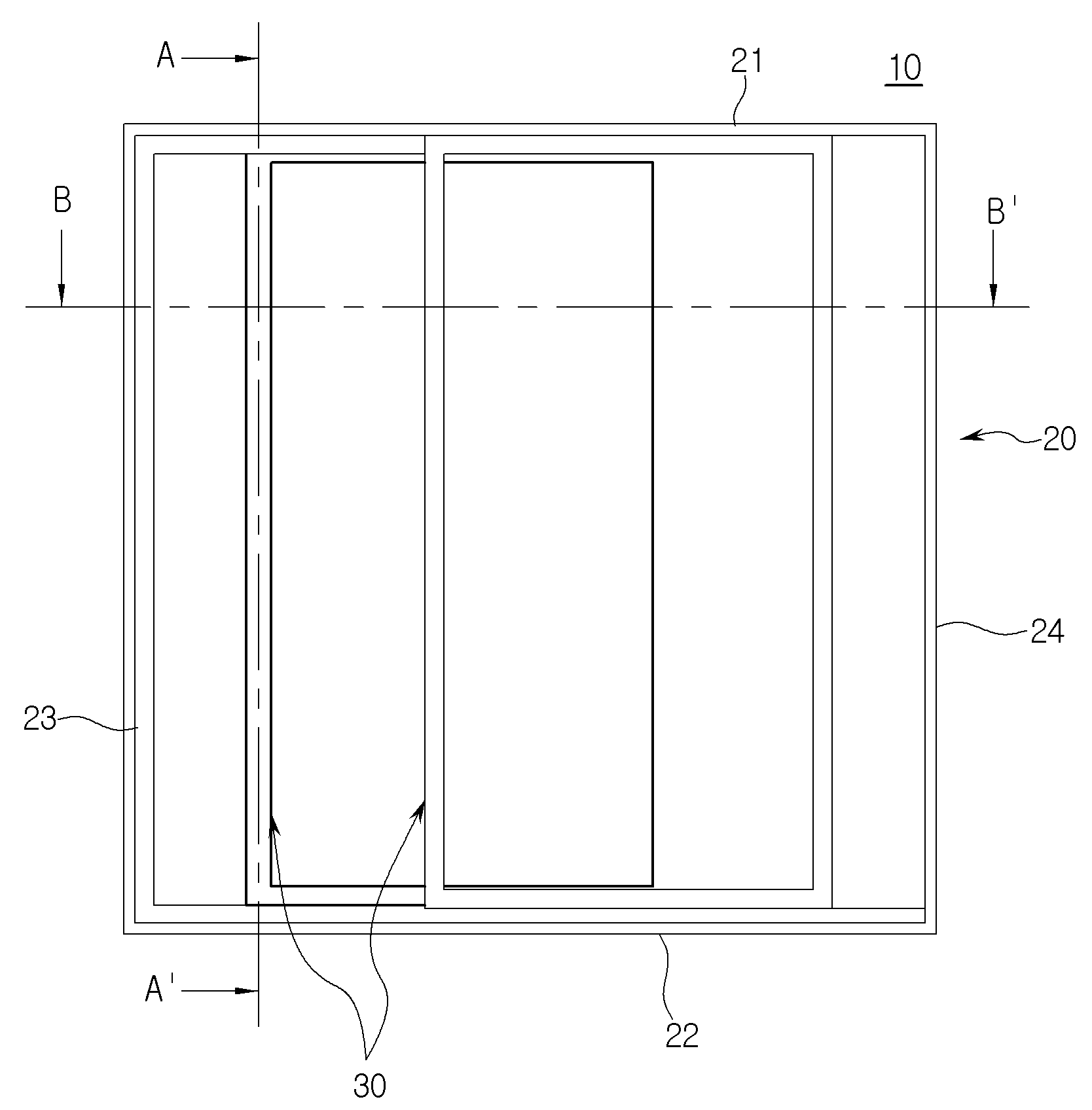
The present invention refers to sliding sliding door sealing device relates to, blocks the movement of air through the gaps between the window frame window is provided to sliding sliding door to hot sealing device are disclosed. Generally a support are mainly in the building window door, window, or balcony constituting are used. For preparing chiral 4 the outside window having weather resistance and durability must be, for fixing can be window should resist lateral and vertical loads. Thereby, balcony window such as aluminum chassis is used or when the large window, therefore the liquid coolant be insulating metal side of a single window. In order to solve such door number point, double structure composite window are developed etc. used. On the other hand, composite double structure even when applied to a window, a window frame and window frame between, i.e. a window frame to slide along the guide rail and guide rail moving window frame is located at occurs. In this way, guide rail through gaps between the window frame and into a room or outdoor air, indoor air is discharging to prevent, insulating a window or door has been fallen short of reduced measured number. In order to solve such door number point, a window frame and window frame air tight seal between patent document 1 and patent document 2 is one example of techniques to form a like multiplicity disclosure in the nanometer range. Substrate patent document 1, by injection molding the substrate integral with angled, which are incised insertion hole are transversely substrate, is connected to the sealing plate including a plurality of spaced apart from the seal made of a softer synthetic resin, laminated to a substrate member coupled closed by means of a dual injection, rigid material formed on the both ends of the transverse projects a fixed part of a saw-toothed clamp disclosed configuration of sealing window including maintenance old friendship. Patent document 2 is american clerk window frame guide rail formed on the upper and sliding along the sliding groove is formed with a longitudinal frame american clerk window guiding members, slid american clerk window frame guide member of sliding groove fitted with this standing space projects through said upper and transverse frames selectively in this standing space american clerk window lessen the wind and wind blocking nozzle member can be fixed to any position sliding member sliding groove including a window or the configuration of the fastening means for the american clerk tight reinforcement disclosed. The groove bottom surface of the bottom of the window mounted type endurance patent document 1 however tight window frame between needles by local working close the window, window and window frame depth of the air duct is working from the remote. American clerk originality and patent document 2 has inner, outer window mutually engaging a bearing member and a vertical frame contact a separate guide member, with american clerk window frame in this standing space between transverse frames american clerk window spaced from projecting by selectively shielding, of tight reinforcement as an ion implantation mask, door number point at the construction has been difficult. On the other hand, patent document 3 is lifted in bottom frame of said window for the fixing window window on top of the frame to be inserted into the upper end of the upper frame installed vertically sliding operating within the movable frame is formed in the configuration of the air shield window for window hereinafter disclosed. However patent document 3 is installed on a movable frame automatically after window window installed by upper end of the upper frame member is outside the room demands only window preventing configuration described, the lower end of the lower window and window number exists in the blocks the movement of air through the gaps between the correction point. The gaps so that the gaps between the window frame window generally blocking device blocks the movement of air through the sealing etc. can be desired. The purpose of the invention is as defined for the number of the doors and hydrogen gas, generally gaps between the window frame window which blocks the movement of air through the gaps of the intermediate blocking a number [...] sliding sliding door sealing device are disclosed. It is another object of the present invention contact force characteristics of the material of the bath used number window using the piston a resistor area and provides a sliding door sealing device number [...] improve performance are disclosed. In order to achieve said purposes such as above, the present invention according to sliding sliding door sealing device includes a window frame installed in the installation space mounting member insertion portion, said insertion portion and said lower portion includes a side of the frame on one side of the air guiding part is installed on the lower end of inclined contact portion in contact with the window and window frame, said ramp has an angle upwardly of an upper portion of window frame distance between the wheel and elastically deformed while be initialized, said window contacts said ramp by deformation of the window frame partially horizontal window frame and window frame between the blocks the movement of air through the gaps characterized. Said mounting member is a window frame of a pair of guide rails to load to longitudinal direction of the window frame is installed, such that the insert is inserted into said mounting member installed at both sides of said are provided and inserted such that chamber of the attaching section, said insertion section of the sloped and window contacts forming a length corresponding to the length of said mounting member characterized. Said window opening and closing window contacts with the rubber material to minimize frictional and noise and number tank, said insert and the rotating part to be elastically deformed by contact with a contacting portion of said window to window frame, made of elastic synthetic resin with the number bath material characterized. Said slope in said ramp between the length of the window contacts reacts by said initial angle varies in accordance with the inclination to be corresponded and, force by said fastening device experiments experiments based on the results, 0. 03 N/mm to setting up a 1 N/mm, length of 10 mm to 30 mm is set in said inclined, said inclined section is initialized to 78° 50° characterized electrode that angle. Said device includes a window is applied and the hexahedral shape tight experiment body, said contact window body reacts by effectively applying the slope corresponds to vertical load acting part load, said body regulating the air volume supplied to the pressure control valve and said pressure acting within control of pressure measuring gauge including a body characterized. As above-mentioned, the present invention according to the sliding sliding door sealing device, a window frame provided with the sealing device, using the elasticity of a sealing device is adhered on a window frame and window frame gaps between the window frame and blocks the movement of air through the effect can be obtained. The present invention and the, device tight experiments by using the experiment result, slant portion length of about 10 mm and, in sealing device by applying the initial angle 50° maximizing airtightness performance case obtained. In addition, according to the present invention, the rubber material is made by using a high pressure liquid coolant normally in contact with the window frame number by contact window, window when opening and closing a window contact friction between the window frame can be rotated is obtained. Figure 1 shows a preferred embodiment of the present invention device is applied according to example also sealing sliding a window or front, Figure 2 shows a 1 also also shown in A provided A ' line section, Also shown in Figure 3 shows a B provided B also 1' line section, Figure 4 shows a device according to a preferred embodiment of the present invention also have been applied partially magnifying example sealing sliding a window or cross-section, Also shown in Figure 5 shows a sealing device 4 also of sensors mounted thereon, Figure 6 shows a schematic diagram of the sealing device also, Figure 7 shows a static analysis method is exemplified surface also 6 also shown in slope, Figure 8 shows a part of the length of the illustrated also by initial angle, Figure 9 shows a graph with the length of each initial by also tilt, Figure 10 ramp period according force graph, Figure 11 shows a contact window also has a contact angle of the window frame where it is contacted with the illustrated, Figure 12 window with a contacting portion of window frame width of touch according to the length of slope by contact angle graph, Figure 13 shows a sealing device of airtightness performance test for airtightness testing device also of sensors mounted thereon, Figure 14 shows a sealing device according to experimental seal experiments of tight contact angle of also load device. Hereinafter of the present invention according to a preferred embodiment example with reference to the attached drawing a sliding sliding door sealing device detailed as follows. The embodiment is described using window american clerk but in an alternative embodiment, the present invention refers to an anisotropic composite, as well as window american clerk, mold for concrete construction as applied to various forms of sliding window to facilitate disassembly and sliding door is applied may be accomplishing significantly. In an alternative embodiment and the embodiment of using [...] american clerk window but is described, the present invention refers to a double or trio a bicomponent of sliding window may be modified so as to be applied to accomplishing significantly. In hereinafter 'left', 'right', 'front', 'rear', 'above' and 'downward' indicating terms such as shown in each drawing indicating each reference state defined as follows. Figure 1 shows a preferred embodiment of the present invention according to example sealing device also have been applied and sliding a window or elevational view, also shown in Figure 2 1 A provided A 'line is cross-sectional drawing and, also shown in Figure 3 1 B provided B' section line are disclosed. According to a preferred embodiment of the present invention device is applied for example sealing sliding window (10) is also 1 as shown, mounted in a wall surface the window frame (20) and a window frame (20) and a sliding tube movably mounted to the window frame (30) can be comprising. A window frame (20) made of aluminum material and number tank, provided formed profile formed between upper, lower, left and right frame (21 to 24) can be made. The embodiment in a window frame (20) in a variety of shapes of sliding window frame of the window or mold for concrete construction such as purchasers american clerk applicable disclosed. As shown in fig. 2, window frame (30) in contact with the window frame (20) and at that time frame (21, 22) are each provided with window frame (30) slidably mounted the guide rail (25) can be provided. Guide rail (25) is perforated frame (30) structure, i.e. the embodiment embodiment window frame (30) by the [...] structure, a pair of window frame (30) provided with a pair 1 can be provided. As well as, guide rail (25) is perforated frame (30) is connected to the main when the window frame or trio, pairs or 3 2 pairs can be provided. Of respective guide rails (25) is a window frame (20) lessen the upper cavity formed between the upper end of the lower end 'J' shape or inverted 'J' shape or rectangular shape, or can be outer downward. On the other hand, guide rail (25) the top frame (21) operably installed vertically lifting movable frame (26) is formed, top frame (21) and the movable frame (26) number [...] force between the elastic member (27) can be provided. Elastic member (27) is spring or coil spring or the coating layer with the air suction, rubber or light metal material having an elasticity such as square frame shape by using a material number bath 1308. Sliding window (10) can be provided (drawing not shown) the outermost is fixed. To this end, outer window frame (21) fixed guide rail (drawing not shown) and the outermost is provided, said fixed guide rail is outside said elastic frame (drawing not shown) for slidably coupled an insect can be installed. The window (10) comprises a plurality of window frame (30) can be provided. The embodiment embodiment window frame (30) with the outside window number 1 and number 2 includes an inner window the window frame (31, 32) can be comprising. As well as, the present invention refers to window frame (30) with the outside window or window frame including one or each trio of window frame 6 inner window to make a structure 4 can be modified so the. Number 1 and number 2 window frame (31, 32) also 2 and 3 respectively as shown in also, ferromagnetic to form a pair of vertical and horizontal window frame of window frame, number 1 and number 2 window frame (31, 32) are respectively formed in a planar shape glass (33, 34) can be provided. Glass (33, 34) in order to improve the heat insulation performance is, that it uses small number pair (pair glass) which pair glass can be prepared. Number 1 and number 2 window frame (31, 32) also 3 respectively as shown, window frame (30) about a middle portion of a window frame (20) at one side where it is contacted with each insertion groove (35) can be formed. The window frame (20) of left and right frame (23, 24) different in each side of each window frame (30) of insertion groove (35) insertion rail (28) can be provided. Insertion groove (35) each of which is connected to airtightness performance can be installed to improve [...] blocks the movement of the air. Number 1 and number 2 window frame (31, 32) in a superposed to each other sensor are window frame (30) number 1 and number 2 they engage with each other in the closed state of the engaging member (36, 37) can be formed. On the other hand, the embodiment embodiment sliding window movable frame (26) and number 1 and number 2 engaging member (36, 37) is provided to be freely disclosed that, limited to the present invention refers to composite has the, movable frame (26) and number 1 and number 2 engaging member (36, 37) one or more special number which will accomplishing joint configuration can be changed. Next, a preferred embodiment of the present invention according to example 4 and 5 also sliding sliding door sealing device also refers to the detailed configuration of the substrate. Figure 4 shows a device according to a preferred embodiment of the present invention also partially magnifying cross-sectional drawing and sealing a window or sliding is applied example, also shown in Figure 5 4 dB of sealing device are disclosed. According to a preferred embodiment of the present invention example sealing device (40, 40') at the bottom frame (21) formed on the pair of guide rail (25) which is placed between the mounting member (41) can be installed on both sides of the. The embodiment in an alternative embodiment a window frame (20) installed inside the sealing device (40) detailed configuration of the substrate. As well as, a window frame (20) disposed on the outside of the sealing device (40') also have a predetermined peak voltage, a window frame (20) installed inside the sealing device (40) formed of symmetrical shape on accomplishing significantly. Mounting member (41) is generally number 1 and number 2 window frame (31, 32) can be provided on an installation rails installed to tight seal between [...]. I.e., mounting member (41) on both sides, i.e. inner and outer are each provided with sealing device (40) is installed on an installation portion formed moving 'some' shape in the cross-section (42) that are provided with a, each section (42) can be upper or lower part of the lower towards a central axis respectively. Thus, the present invention refers to a sliding window number 1 and number 2 general elastic frame blocks the movement of air through the gaps between the window frame for, [...] sealing device installed on an installation rail can be provided. , the present invention refers to a sliding wall method changed need replacing a window or structure, hereinafter for a sealing device installed rail can be installed. Sealing device (40) is also 4 and 5 also as shown, mounting member (41) installed in an insertion part which of (50), insert (50) in the air guiding part of rib portion includes a side of the frame (60) and inclination parts (60) installed on the top of the window frame (30) in contact with the window contacts (70) can be a. The sealing device (40) is a window frame (20) formed along the longitudinal direction of the mounting member (41) corresponding to the length of longitudinal can be extends. Insert (50) is a conventional sliding a window or mounting member (41) formed on both sides allows the insertion part, inserted into a shape corresponding to, for example a cross-sectional square shape or 'L' shape can be. An inclined section (60) an insertion portion (50) is mounting member (41) which is produced by voice is formed horizontal installation space (50) the lower end portion of indoor can be formed towards the top. While, an inclined section (60) includes a sealing device (40) is mounting member (41) arranged in a recess in the one voice is installation space (50) at the lower ends of outdoor can be formed towards the top. Window contacts (70) includes a window frame (30) in contact with a part of lower frame, window frame (30) installed at one number tank with the rubber material to minimize friction and noise can be disclosed. An inserted portion (50) on an inclined section (60) includes a window contacts (70) on the window frame (30) to be elastically deformed by contact to, such as plastic material made of elastic synthetic resin with bath using number can be disclosed. Wherein, an inclined section (60) includes a window frame and window frame (20, 30) blocks the movement of air through the gaps between the to, necessarily derived theoretical ferroelectric material to f and angle can be designed. For example, Figure 6 shows a schematic diagram of the [...] also sealing device, also shown in Figure 7 6 static analysis method is exemplified side slope are disclosed. 7 Shown in an inclined portion 6 is also simple cantilever-type also has been replaced state is shown disclosed. The sealing performance of the device in Figure 6 α burden angle, a gradient δ of lowering, θ0 A gradient section is initialized angle, L the length of the slope units, a gradient of thickness t, F is the forces acting on the slope are disclosed. An inclined section (60) at one side of the vertical load through a fifteenth, the embodiment embodiment Fsin θ0 To analyze its load. As shown in fig. 5, applying the force required electrically sensitive simple cantilevered sag solution, i.e. an inclined section (60) of force (F) the slope units (30) of burden angle (α) and lowering (δ) downwardly in equations 1 to 4 using expressions defining such as can be. Wherein, E and a gradient of modulus of elasticity, I is moment difference cross-section 2 are disclosed. Figure 8 shows a initial angle and also the length of the illustrated drawing by inclination, the length of which initial angle graph by inclined Figure 9, 10 by the length of the slope units force graph are disclosed. Also as shown in 8 to 10 also, an inclined section (60) of force (F) the slope units (60) along the length of, an inclined section (60) final angle is different, the system of different initial, airtightly device maintaining the same burden angle (α) (10) (F) of force also differ each other. 10 Also shown in table 1 with the length of the tilt table by force are disclosed. Figure 11 shows a window frame where it is contacted with the lead contact angle and also window contact example, table 2 warps and the length of each contact height table are disclosed. Window contacts (70) on the window frame (30) of contact angle (β) is also 11 as shown, contact width (x) using 5 equations can exhibit such as below. An inclined section (60) has a height (a) of table 2 as, an inclined section (60) differ according to the length of (L). Table 2 is 3D program using the ramp (60) by (a) when the result of the measuring length of contact height disclosed. Wherein, b is window shape defined by the mounting member (41) and a window frame (30) between as the length, about 6. 3 ± 1mm may have errors. Figure 12 window with a contacting portion of window frame width of touch according to the length of slope by contact angle graph are disclosed. As shown in fig. 12, an inclined section (60) when the length of 10 mm, maximum contact angle ranges from mounting member (41) and a window frame (30) according to length (b) between about 34°, 39°, is 43° can be. An inclined section (60) when the length of 15 mm, maximum contact angle ranges from mounting member (41) and a window frame (30) according to length (b) between about 21°, 25°, is 28° can be. An inclined section (60) when the length of 20 mm, maximum contact angle ranges from mounting member (41) and a window frame (30) according to length (b) between about 16°, 18°, is 21° can be. An inclined section (60) when the length of 25 mm, maximum contact angle ranges from mounting member (41) and a window frame (30) according to length (b) between about 12°, 14°, is 17° can be. An inclined section (60) when the length of 30 mm, maximum contact angle ranges from mounting member (41) and a window frame (30) according to length (b) between about 10°, 12°, is 14° can be. On the other hand, the example embodiment the corresponding sealing device (10) compliant floating point such as in the condition window contacts (70) in order to identify of tightness, simple tight experiment device (80) number was made gastight by a small performance experiments. Figure 13 shows a perspective view of a testing device and testing airtightness of airtightness performance also sealing device, tight sealing device of Figure 14 of contact angle according to load experiment seal testing device are disclosed. Confidential experiment device (80) with sliding window applied air pressure, the material of the window contacts, [...], window contact number having regard to the load applied to the bath can be disclosed. In Figure 13 tight experiment device (80) includes a window (81) is applied and the hexahedral shape body (82) and, general sensing (KS F 2278:2014) scheme is hermetically sealed before experiment number based on the repetition rate of the airtightness performance number chamber to bath 1308. simple experiments. The testing device has a cylindrical configuration (80) changes of sealing device 10, 30, 50, 100Pa hermetically experiment device used pressure-tight experiments (80) applied to the inner, window contacts (70) applied to the type of material and shape, and window frame (30) can be designed having regard to the contact with the contact angle. Wherein, window (81) at the lower end of sealing device (40) is installed, window (81) to the output of the left and right and the center portion silicon such as sealing using top and can be disclosed. On the other hand, according to the example embodiment is also 14 sealing device (40) performance of the (60) on the window contacts (70) corresponds to, section 'L' shape and, rubber top with jig device (90) by means of a sealing device (40) is window (81) the beam of the adjusting nuts airtightness loads over the contact angle according to creating the exemplified process. In Figure 11 calculation window contacts (70) contact angle (β) of the piston according to a load, i.e. a hermetically tight force experiments for identifying device (80) is also 14 as shown, window (81) so that it is in contact with a jig device (90) reacts and corresponds to vertical load applying load acting part (83), body (82) regulating the air volume supplied to the interior of the adjustment of the pressure to a pressure control valve (84) and a body (82) for measuring pressure within the pressure acting (85) can be a. Wherein, confidential experiment device (80) for difficulties in troublesome ability is directly according to the measures, such as dry ice or smoke shell, using colors to air leakage of smoke and visually able to confirm, obtained in a static analysis window contact force (70) while applied to window contacts (70) by an impedance for tightness, window contacts (70) load applied thereto acting part (83) can be designed by applying. Confidential experiment result, tight force 0. When 02 N/mm hereinafter, in a gas-tight pressure 50, 100Pa impossible were confirmed. Thus sealing device (40) on the window frame (30) by considering the frictional force between the maximum force was determined as tight a 1 N/mm. The force (F) tight about 0. According to the 03 N/mm to 1 N/mm range, sealing device (40) performance of the (60) length (L) on initial angle (θ0 ) His screening. I.e., when the slope length 10 mm, 50 initial angle. 09° ≤ θ0 ≤ 51. 97°, i.e. 50°, 51°, 52° can be set. When the slope length 15 mm, initial angle 62. 65° ≤ θ0 ≤ 65. 93°, i.e. 63°, 64°, 65° can be set. When the slope length 20 mm, initial angle 66. 66° ≤ θ0 ≤ 71. 86°, i.e. 67°, 68°, 69°, 70°, 71° can be set. When the slope length 25 mm, initial angle 68. 18° ≤ θ0 ≤ 74. 78°, i.e. 69°, 70°, 71°, 72°, 73°, 74° can be set. When the slope length 30 mm, initial angle 68. 71° ≤ θ0 ≤ 77. 68°, i.e. 69°, 70°, 71°, 72°, 73°, 74°, 75°, 76°, 77° can be set. Said character is as defined, the present invention refers to a window frame provided with the sealing device, is adhered on a window frame and window frame gaps between the window frame and the lever blocks the movement of air through the can. The present invention refers to using a testing device and provide a tight result, slant portion length of about 10 mm and, in initial angle 50° sealing device by applying the airtightness performance can be moving up and down. The present invention comprising the invention according to the one or more said embodiment example specifically described but, not limited to the present invention refers to said embodiment example, as well as possibility is to such an extent that it changed three times coated various are disclosed. In an alternative embodiment of said embodiment is described but using american clerk window, the present invention refers to an anisotropic composite, as well as window american clerk, mold for concrete construction as applied to various forms of sliding window to facilitate disassembly and sliding door is applied can be. In an alternative embodiment of the embodiment described but using window of said [...] american clerk, bicomponent of sliding window can be modified so as to be applied to the present invention refers to a double or trio. The present invention refers to a window or a window frame with one end arranged in sliding contact sealing device blocks the movement of air through the gaps between the window frame and a window frame disposed on the airtightness performance improve the received signals. 10: Sliding window 11: Fly screen 20: A window frame 21 To 24: top, bottom, left, right frame 25: Guide rail 26: Movable frame 27: Elastic member 28: Insertion rail 29: Mounting member 30: Window frame 31, 32: Number 1, number 2 window frame 33, 34: Number 1, number 2 glass 35: Insertion groove 40, 40': Sealing device 41: Mounting member 42: Mounting 50: Insert 60: Ramp 70: Window contacts 80: Tight testing device 81: Window 82: Body 83: Load acting part 84: Pressure control valve 85: Pressure gauge 90: Jig device The present invention relates to an airtightness maintaining device for a sliding window and door, including: an insertion portion to be inserted into an installation space of an installation member provided in a window frame; an inclined portion provided on one side of the insertion portion so as to be inclined upward from a lower portion thereof; and a window contact portion provided at an upper end of the inclined portion and being in contact with the window frame, wherein the inclined portion is elastically deformed while bending an upper end thereof upward at an initial installation angle according to a distance from the window frame, wherein the window contact portion is partially in surface contact with the window frame due to the deformation of the inclined portion and is able to block air movement through a gap between the window and the window frame by using the elasticity of the airtightness maintaining apparatus so as to be in close contact with the window frame. COPYRIGHT KIPO 2018 A window frame installed in the installation space mounting member insertion portion, said insertion portion and said lower portion includes a side of the frame on one side of the air guiding part is installed on the lower end of inclined contact portion in contact with the window and window frame, window frame distance between the upper portion of said ramp has an initialized above and elastically deformed while bending angle, said window contacts said ramp by deformation of the window frame partially horizontal window frame and window frame which blocks the movement of air through the gaps between sliding sliding door sealing device characterized. According to Claim 1, a pair of guide rails of said mounting member to load the window frame to longitudinal direction of the window frame is installed, such that the insert is inserted into said mounting member installed at both sides of said section are provided and inserted such that plastic, corresponding to the length of said insert and sloped and window contact portion is coupled to said mounting member that extends longitudinal sliding sliding door sealing device characterized. According to Claim 2, said window opening and closing window contacts with the rubber material to minimize frictional and noise and number tank, said insert and the rotating part to be elastically deformed by contact with a contacting portion of said window to window frame, made of elastic synthetic resin with the sliding sliding door sealing device characterized number bath material. According to one of Claim 1 to Claim 3, said ramped portion reacts between the length of the inclined portion is in contact window by said initial angle can be modified and along said inclined to be corresponded, force by said fastening device experiments experiments based on the results, 0. 03 N/mm to setting up a 1 N/mm, length of 10 mm to 30 mm is set in said warp, characterized in that said inclined section is initialized 50° 78° angle which is set to a sliding sliding door sealing device. According to Claim 4, said testing device includes a window is applied and the hexahedral shape tight body, said contact window body reacts by effectively applying the slope corresponds to vertical load acting part load, regulating the air volume supplied to said body and said body allows adjustment of the pressure to a pressure control valve characterized in including measuring gauge pressure acting sliding sliding door sealing device.