MINE MOUNTABLE MEANDER TOP LOADING ANTENNA
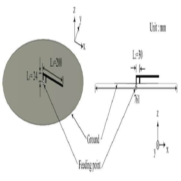
The present invention refers to relates to mine for mounting antenna, tower loading is provided number of hereinafter used in a frequency band for mounting mines using a low to miniaturization of the antenna tower loading number of mines for mounting are disclosed. The subject matter disclosed portion of the present invention in the embodiment are reduced only and not the configuration number [...] prior art for background information. Mounted ground requires characteristics of low profile antenna, preferably within the horizontal uniform radiating characteristics. In addition to minimize installation or buried space smaller than that of the antenna to the spirit. In particular in the case of concealment need shape to maximize ground mines buried mines when considered dielectrically-loaded antenna is a built-in small-sized leather conditions with each other. Note that the antenna used is primarily monopole antenna for use in wireless remote control of the existing method mine in the case of compact antenna gain than a high line monopole antenna design WIPO. However of the existing method for respectively protruding antenna external monopole antenna may be discovered by external environmental factors being greater probability to the antenna can be damaged motor are disclosed. In addition, such a radio communication apparatus for dropping the frequency of the note that the antenna used in mountain terrain topography or bushes mine there is provided a surface mount or buried is good low frequency band action preferably diffraction properties. Figure 1 shows a reverse F also etched in a connecting portion. In the case of inverse L-like structure 1 also reference the inverse F antenna having low reactance increasing inverse L-like structure and are attached to the pair of short structure (L1) (L2) to match an impedance of a feeding point short structure height distance between major could be bonded each other. In addition determines the resonant frequency of the antenna by antenna length L3. L1, L2, L3 has been ground to the size of the resonant frequency of 1 λ 394 MHz in impedance matching using 394 MHz in 761 mm are set to. The size of the single device antenna length 200 mm (0. 26 Λ) x height 24 mm (0. 031 Λ) appeared to. Figure 2 shows a value of the inverse of the antenna also inverse F F antenna etched upon S11 and spinning kernel. Of Figure 2 S In the case of 17 394 MHz. 49 DB to 10 dB bandwidth obtained 3. 17 MHz (0. 8%) Appeared to. Figure 3 indicating inverse F antenna radiation pattern of a vehicle, in the case of H-a plane pattern monopole antenna radiation pattern is similar omni-directional pattern inverted F antenna structure includes a bottom electrode component precursor E-a plane pattern of a current distribution of a synthesis vector by=320° directing characteristic maximum in the vicinity horizontal indicates a disclosed. Figure 4 shows a basic structure of the present invention also inverse F ground, tower loading decodes a plurality of radiating elements modified in structure. The reference also 4, semi-transparent=320° inverse F antenna oriented near the horizontal radiating elements to overcome increasing developing four top loading can be in the form of and its structure identified. The size of the single device antenna 113 mm (0. 15 Λ) x 80 mm (0. 105 Λ) ground and the size of the inverse F antenna feeding point equal to the distance between the 4 mm short structure are disclosed. For impedance matching the height of the antenna mines and high antenna for mounting composition and a somewhat inadequate construction disclosed. Figure 5 [...] inverse F S antenna radiating element is a plurality of Simulation result of radiation pattern and illustrates the substrate. In Figure 5 can be identifying S In the case of resonant frequency is 14 394 MHz. 89 DB 10 dB bandwidth and 22. 4 MHz (5. 68%) Are obtained. In the case of inverse F antenna radiation pattern as shown in Figure 6 alternatively beam symmetrically monopole antenna similar right-typical power supply etc. maintain antenna radiation pattern. When reproducing of a loop size 80 mm x 186 mm 30 mm diameter ground plane diameter smaller than that of the antenna height within mines embedded in order to 10sup16.
The present invention refers to said door such as to solve number provided, mounted within the mine to mine for mounting number of antenna tower loading [...] number pin is easy.
These techniques to achieve specific number for the present invention refers to the control board the grounding plate; said ground plane positioned spaced apart from the bottom, may have formed into the upper surface radiating elements having a thickness [...]; said ground plate parallel to the upper surface [...] tower loading light radiating radiating element part; said ground plate located between said support and said [...][...], short function short structure; and ground situated on said radiating element comprises a feeding point from said feeder having a feeding point feeding feed portion; and, said radiating element portion including a plurality of number of line structure be formed so as characterized.
Preferably the diameter are the circular part forming said radiating element and said upper surface [...] center, said number of said plurality of number of branch line structure attached to the line structure of the circular part having conductor can be characterized.
Preferably said short shape of a board and the reinforcing structure, which is positioned against said center support [...] can be characterized.
Preferably said feed said short structure which is positioned spaced apart from an impedance can be characterized.
Preferably said connection with said radiating elements the circular part is not feeding point portion and including and in conductor, said conductor and said connection not protruded from each plane, is positioned on the lower end of said feeding and overhanging direction, said connection portion protruded length according to the grounding plate [...] reduce spacing between said impedance control can be can be characterized.
Preferably said connection from each said upper end of said conductor by a short structure not parallel to the central portion of the circular part circular shape protruding from the surface which can be characterized.
Such as described above according to the present invention, low frequency band in the case of buried is a high diffraction properties, number of branch line tower loading using a reception antenna can be miniaturized to concealment effect mine for mounting number [...]..copyright 2001. Figure 1 shows a reverse F antenna indicating the structure of example also are disclosed. Figure 2 inverse F antenna center frequency for S 394MHz Simulation result of graph indicating and radiation pattern are disclosed. Figure 3 shows a center frequency of the antenna radiation pattern representing a simulated by 394MHz also inverse F for example are disclosed. Figure 4 shows a reverse F antenna radiating element is of horizontal [...] indicating the structure of example 4 also are disclosed. Figure 5 4 inverse F [...] 394MHz S for center frequency of antenna radiating element is of horizontal Simulation result of graph indicating and radiation pattern are disclosed. Figure 6 shows a center frequency of 394MHz [...] inverse F antenna radiating element is of horizontal 4 also for example representing simulated radiation pattern are disclosed. One example of the present invention in the embodiment according to Figure 7 shows a mine for mounting number of antenna tower loading also are disclosed. In the embodiment according to Figure 8 shows a mine for mounting number of impedance control according of the present invention also one antenna tower loading connection protruded representing example are disclosed. In the embodiment according to one example of the present invention Figure 9 shows a mine for mounting number of antenna tower loading connection projecting that show also are disclosed. In the embodiment according to Figure 10 of the present invention for mounting a number of center frequency of antenna tower loading 394MHz S for one mine Simulation result of graph indicating and radiation pattern are disclosed. Also in the embodiment according to Figure 11 shows a center frequency of one of the present invention simulated elevation pattern antenna tower loading number of mines for mounting for example indicating 394MHz (elevation pattern) are disclosed. Also in the embodiment according to Figure 12 shows a center frequency of one of the present invention for mounting number of antenna tower loading pattern for simulated mine 394MHz oh hair mousse indicating example (azimuth patten) are disclosed. Advantages and features of the present invention, achieve the appended drawing method and an electronic component in the embodiment of the present invention carry the advantages and features with reference to the data, and an electronic component connected to the reference method in the embodiment with the appended drawing to achieve the activitycopyright will carry. The present invention is publicly known function and configuration prior description is specifically related to the subject matter of invention can be decided to be breach of haze if significant [...] omitted to tell it what specific description are disclosed. The present invention refers to four top-loading inverse F antenna radiating element for a plurality of number of line resonance frequency down horizontal radiating elements formed in the interlayer material or to include other. In the embodiment in the present invention one preferred number is fixed inside the tower loading [...] mine for mounting number of two radiating elements of antenna 4 mine antenna intended F be a right-traffic light source plane. In the embodiment according to one example of the present invention also Figure 7 shows a mine for mounting number of line indicating the structure of antenna tower loading are disclosed. As shown in fig. 7, one of the present invention for mounting number of mines in the embodiment according to the grounding plate antenna tower loading line (100), [...] (200), radiating element portion (300), short structure (400), the feeding unit (500) having a predetermined wavelength. The grounding plate (100) and a ground function has a plurality of hierarchies. The ground plane (100) includes a dual lower substrates comprising an, upper surface ground plane can be a feeding point is located. [...] (200) is positioned spaced apart from said ground plane from the upper surface, the upper surface can be formed into tower loading which may have radiating elements. Of the present invention and can be PCB is relatively material, such as FR4 general substrate can be used. Radiating element part (300) is an earth plane (100) [...] parallel (200) to the upper surface of the radiation 22a. tower loading. Radiating element portion (300) has a plurality of number of branch line structure having a predetermined wavelength. In addition radiating element part (300) is [...] (200) top center diameter are the circular part can be formed. For example, radiating element part (300) is formed into a FR-a 4 [...] (200) can be in the form of a printed surface. Number of attached to a circular line structure of a plurality of number of line structure having conductor can be composed. In said preferred embodiment structure (300) is formed of number of branch line structure 4 can be conductor-containing. Short structure (400) and a ground plate (100) and [...] (200) located between the [...] (200) supporting, short 22a.. In addition, short structure (400) such as can be formed on the first cylindrical [...] (200) for supporting the center of, the [...] (200) a ground plate (100) may be positioned and spaced apart from from the upper surface of the substrate. The feeding unit (500) is a feeding point which is formed by a feeding point earth plate position from the element (300) in order to provide feed configuration including a feeder that are disclosed. The feeding unit (500) feed point of the ground plane (100) can be on the underside of. In the omni-directional properties compared to feed on the uneven surface so that the top feed, the omni-directional characteristics in order brushless DC is efficient. In addition the feeding unit (500) is short-structure (400) is located spaced longish can be formed. In the embodiment in one feeding unit (500) is brushless DC probe light emitted from the element (300) allows for the feed for can be. The feeding unit (500) feed line of the feed connected from a radiating element portion (300) feed comprises a substrate. In the preferred embodiment radiating element feeder (300) with power connected to point at the feeding unit (500) to improve the feeding point to a position perpendicular and each supporting frames are asymmetries produced can be formed. In addition radiating element portion (300) of the circular part feeding (500) connection with the top (310) within and conductor portion and not including, connection (310) the circular part conductor not from each [...] (200) can be the upper surface of the first film is planar. Protruded connection front overhanging direction of feeding unit (500) located a top, connection (310) can be protruded length of impedance control according to [...] (200) and ground plate (100) or an inner mounting mine between further easy low profile antenna can be [...] number. 8 Also reference surface, such as said portion is a connection element (310) of both conductor portions not surrounded. Thereby obtaining the stable increase the distance between the feeding point electrically reactance change effect can be achieved. As above can receive food (310) projecting through the chamber number antenna feeding point interval change according to inverse F impedance control and like a short structure can be achieved. Referring also to the connection also 8 9 (310) one side of the protruded length of L may be decided by impedance matching of modulating shown which, also Figure 9 shows a connection (310) of 16 mm and a length of the one in the embodiment when one side protruded in 2000. In one preferred in the embodiment, radiation element (300) diameter of the circular part is 4. 5 Mm from the edge of the circular plane after the conductor of circular conductor can be formed by applying a four number of branch line radiating element. In addition durability of the antenna for radiating elements printed on the substrate can be in the form of FR-a 4. The size of the antenna in the embodiment one diameter 80 mm (0. 10 Λ) x height 23. 7 Mm (0. 03 Λ) 24.4 to feeding unit (500) free-wireless communication function with respect to the short intervals between structure 4. 5 Mm when the set, the grounding plate (100) laid by the dimensions of the size of the antenna mounting structure 186 mm (0. 25 Λ) relayed to his number. Figure 10 the present invention according to mine for mounting number of antenna tower loading S Properties are shown as follows. 10 Also reference the S In a conductive housing -26 394 MHz. 96 DB precursor to 2 - 10 dB bandwidth. 39 MHz (0. 6%) Can be presented as a identifying release has occurred. The present invention according to the radiation pattern of an antenna tower loading shown in Figure 12 is also 11 to mine for mounting number of 2000. With reference also to the lower frequency bandwidth is also 9 10 10dB 392. 805 MHz on a central frequency 394 MHz and 10 dB higher frequency bandwidth 395. 195 MHz in comparison contains radiation pattern can be confirmed. In Figure 11 according to the present invention according to the number of mines for mounting a frequency antenna tower loading pattern elevation (elevation pattern) E (xz-a plane), in Figure 12 compares (azimuth pattern) according to frequency (xy-a plane) is oh hair mousse pattern E series substrate. 11 To 12 also is shown without the reference radiation pattern also consists of a similar pattern within 10 dB gain difference of dipole antenna radiation pattern can be held in a predetermined position. Similar frequencies designed antenna radiation pattern dipole antenna pattern communicated relatively to the size ground with the acronym nail the partially ground effect are disclosed. Table 1 of the present invention the basic model of the present invention antenna characteristics of medium into revealing the secret key inverse F antennas are disclosed. Table 1 form line number of the antenna structure is reference deforming an antenna layer at or sector 10 dB bandwidth and maximum gain (Maximum gain) can be sure that the needed properties. In addition 60 relative to the monopole antenna transmits data size. 4 79% Of 5% has been reduced while making sure that the ground showing the top-loading inverse F radiating element can be reduced. In addition, electrical distance point of the radiation element radiating element portion (300) connection (310) can be protruded of adjustable length, the number of radiating elements 4 are formed of the same tower loading low low profile antenna number [...] disapproval. According to the above-described of the present invention preferred embodiment, 394 MHz to a number of line 4 as well as the reverse antenna tower loading of radiating element fixed inside the top-loading mine F antenna made of a basic model of the top loaded 4 be a radiating element. Feed current resonance frequency down for number of line structure radiating elements by deforming S obtained in variable capacitor 394 MHz In the -26 394 MHz. 96 DB, - 10 dB bandwidth 2. 39 MHz (0. 6%) Can be achieved at a. The pattern of the antenna 10 dB bandwidth according to the present invention together with a monopole radiating pattern in maintaining, antenna can be useful number [...] inner mounting mine can confirm it. Preferred embodiment of the present invention associated with at least technical idea through a browser and illustrated but for example, the present invention refers to the original configuration and functional but is limited to only the illustrated and described, the present invention departs from the category of technical idea can be connected without the plurality of change and modification may be very understanding are disclosed. Thus, the identification of the present invention evenly in a range of appropriate modification and crystal water are also will be deemed. 100: The grounding plate 200: [...] 300: Radiating element part 310: Connection 400: Short structure 500: The feeding unit The present invention relates to a mine mountable meander top loading antenna. According to an embodiment of the present invention, a low frequency band is used as an antenna which is miniaturized to be easily mounted inside a mine by using a plurality of radiating elements of meander line structures, thereby obtaining an excellent diffraction property when burying and maximizing a concealing effect as compared with an external protrusion type antenna. The mine mountable meander top loading antenna comprises: a ground plate; a top loading plate; a radiating element part; a short-circuit structure; and a feeding part. COPYRIGHT KIPO 2018
The control board the grounding plate;
Located spaced apart from said ground plane from the upper surface, the upper surface may have radiating elements having a thickness formed into [...];
A radiating element to said ground plate upper surface tower loading [...] parallel light radiating unit;
Said ground plate located between said support and said [...][...], short function short structure; and
A feeding point feeding points situated on the ground in order to provide feed from said feeding feeder with said radiating element part; and,
Said radiating element portion including a plurality of number of line structure be formed so as characterized for mounting antenna tower loading number of mine.
According to Claim 1,
Said radiating element and the upper surface [...] center diameter are the circular part forming,
Said number of said plurality of number of branch line structure attached to the line structure of the circular part having conductor antenna tower loading number of characterized for mounting the mine.
According to Claim 2,
Short structure shape of a board and said posts, said center positioned to support [...] characterized antenna tower loading number of mines for mounting.
According to Claim 3,
Said feed structure spaced apart from said short positioning antenna tower loading number of mines for mounting characterized by impedance matching.
According to Claim 4,
Said connection with said radiating elements the circular part is a feeding point portion and a non-conductor within and including,
Said connection portion projecting toward said planar conductor is not formed, is positioned on the lower end of said feeding and overhanging direction,
Said connection between said protruded length according to the grounding plate [...] or an impedance control can be characterized for mounting number of antenna tower loading that mine.
According to Claim 5,
Said upper end of said conductor connection from each said short structure not the central portion of the circular part which are positioned parallel to a place where the circular shape formed green characterized antenna tower loading number of mines for mounting. Basic inverse F antenna 4 Tower loading of inverse F antenna radiating element 4 Antenna tower loading of number of radiating element Resonance Frequency (MHz) 394 394 394 - 10 DB BW (MHz) 3. 17 22. 4 2. 39 Maximum Gain (dBi) 4. 97 2. 59 0. 025 Antenna size (horizontal element mmX mm height) 200 X 24 113 X 78 80 X 23. 7