Rod-in-tube optical fiber preform and method
[0001] 1. Field of the Invention [0002] This invention relates to optical fiber preforms, and particularly to such preforms of the rod-in-tube (RIT) variety. The invention also concerns a method of drawing an optical fiber using a RIT preform. [0003] 2. Discussion of the Known Art [0004] Optical fibers for data and information transmission are commonly produced by inserting one end of a glass fiber preform rod into the mouth of a vertical fiber draw furnace, and heating the inserted end of the rod as it descends into a hot zone of the furnace. A soft glass drop is formed at the end of the rod from which an optical fiber is then drawn. The preform rod itself may be produced, e.g., by a modified chemical vapor deposition (MCVD) process by which the rod acquires a refractive core region extending axially of the rod, and a cladding region which surrounds the core region. See U.S. Pat. No. 4,217,027 (Aug. 12, 1980), all relevant portions of which are incorporated by reference. [0005] As disclosed in the '027 patent, preform rods produced by the MCVD process involve the passage of gases such as SiCl4 and GeCl4 axially through a hollow silica glass tube. The tube is rotated about its axis and simultaneously heated from outside by a torch while the gases pass inside the tube, thus causing a layer of submicron sized glass particles to be deposited on the tube's inner circumference. By moving the torch repeatedly along the long direction of the tube, multiple layers of glass particles are deposited inside the tube. Once a determined number of layers are formed, the tube is heated again until it softens and collapses into the shape of a solid rod with the deposited glass particles forming the core region and the collapsed glass tube forming the cladding region. [0006] The described MCVD process does, however, impose a limit on the maximum wall thickness of the glass tube. That is, as the wall thickness increases, the rate at which heat is transferred from the outside moving torch to the reactant-containing gases inside the tube, decreases. If sufficient heat transfer does not occur, bubbles or incomplete sintering can occur in the deposited glass layers. To overcome this condition, the rate at which the outside torch moves is decreased, thereby increasing the overall time needed to deposit each glass particle layer. Yet, the greatest tube wall thickness that a given MCVD process can tolerate still may not be adequate to yield a sufficient amount of cladding on the drawn fiber for certain applications. This problem is overcome by the rod-in-tube (RIT) method. [0007] In the RIT method, a preform rod made, for example, according to a MCVD process is inserted axially within a so-called glass overclad tube. The overclad tube is heated so as to soften and collapse onto the preform rod, wherein the tube glass consolidates with the cladding on the preform rod. An optical fiber having an outer (cladding) diameter greater than that which could be attained from the MCVD preform rod alone, is then drawn from the combined preform rod and overclad tube. This process is also sometimes referred to as overclad during draw or ODD. See also commonly owned U.S. patent application Ser. No. 09/515,227 filed Feb. 29, 2000, and entitled “Apparatus and Method For Making Multiple Overclad Optical Fiber Preforms and Optical Fiber Therefrom”, all relevant portions of which are incorporated by reference. [0008] According to the method disclosed in the mentioned '227 application, a preform rod is positioned inside a first overclad tube, and a second overclad tube is disposed over the first overclad tube. The preform rod and the overclad tubes are heated under such conditions as to cause a partial collapse of the tubes at one end of the rod, thus forming a unitary multiple overclad preform rod. The one end of the overclad rod is later set up for insertion into a vertical fiber draw furnace, and an ODD fiber having a desired outer diameter and core-to-cladding mass ratio is produced as remaining portions of the tubes collapse and consolidate with the cladding on the rod. [0009] The preform rod may also be provided in the form of a solid glass rod comprised of desired core material only, with the overclad tube(s) serving as the only source of cladding material on the fibers to be drawn. Accordingly, the preform rod as described above in connection with the RIT process will be referred to hereafter simply as a “core rod”, whether the rod is formed to have an outer layer of cladding material, or is comprised solely of core material. [0010] A problem that arises when carrying out the known RIT methods concerns the additional heating step prior to fiber draw, wherein the preform comprising a core rod and one or more coaxial overclad tubes is consolidated and sealed at the one end to hold the rod and surrounding tubes together for insertion into the draw furnace during start-up. This preliminary step is not desirable since it entails a significant added expense, viz., capital intensive overclad lathes, and heat source and material handling equipment. The step also produces significant stress in the preform glass when it cools and is then later re-heated in the fiber draw furnace. Such stresses create a high tendency for the preform to crack and fracture, and greatly increase repair rates, scrap and waste. Further, in an attempt to alleviate the problem, special measures must be implemented such as, e.g., increasing the insertion time of the preform in the draw furnace when drawing fiber. [0011] According to the invention, an overclad optical fiber preform includes a core rod, and an overclad tube having a first open end and a second open end opposite the first open end. The first open end of the overclad tube is dimensioned to enter into a mouth of a vertical fiber draw furnace. A plug is supported within the first open end of the tube, and the core rod is disposed axially inside the tube so that a distal (i.e., lower) end of the rod is restrained from downward movement by the plug when the first open end of the tube enters the mouth of the draw furnace and descends into a hot zone of the furnace. [0012] According to another aspect of the invention, a method of drawing an optical fiber includes inserting a core rod inside an overclad tube, inserting a plug in an open distal end of the overclad tube, and fixing the plug in the vicinity of the distal end. The distal end of the overclad tube is positioned for insertion into a mouth of a vertical fiber draw furnace. The overclad tube descends into and is heated by the draw furnace until the plug and the tube soften and fuse with one another. The tube then collapses onto the core rod to produce a drop from which an optical fiber having desired properties may be drawn. [0013] For a better understanding of the invention, reference is made to the following description taken in conjunction with the accompanying drawing and the appended claims. [0014] In the drawing: [0015] [0016] [0017] [0018] [0019] [0020] [0021] In the illustrated embodiment, the fiber preform 10 includes a core rod 18 and a glass overclad tube 20, lower portions of which are shown in [0022] The taper angle T approximates a neck down inclination 13 that is assumed by the lower end 16 of the preform 10 when it softens in a hot zone 15 of the fiber draw furnace 14 to form a glass drop 17, as seen in [0023] A cylindrical plug 22 is supported inside the open distal end of the glass overclad tube 20. The plug 22 is formed, e.g., from commercially available natural or synthetic fused silica, or equivalent material. Openings 24, 26 are drilled or otherwise formed through the conically shaped wall of the tube 20 at diametrically opposed locations at the distal end of the tube, and along an axis O (see [0024] During assembly of the preform 10, the overclad tube 20 may be supported horizontally, and an upper end (not shown) of the rod 18 is inserted axially into the open, distal end of the tube 20. Preferably, the rod 18 and the tube 20 are dimensioned so that a radial clearance gap G of, e.g., 1 mm +/−0.5 mm exists between the inner periphery of the overclad tube 20 and the outer periphery of the inserted rod 18. The plug 22 is then placed into the distal end of the tube 20 so that opposite ends of the plug bore 30 register with the openings 24, 26 in the tapered tube wall, and the pin 28 is inserted as explained above. [0025] When the assembled RIT optical fiber preform 10 is vertically oriented as shown in [0026] In accordance with the invention, the RIT preform 10 is assembled in a relatively simple manner with no requirement for joining a part of the overclad tube 20 to the core rod 18 by a separate heating step prior to fiber draw. By eliminating the prior heating step, manufacturing costs are significantly reduced and the yield obtained from the preform 10 increases. Moreover, various preform sizes and fiber types (e.g., single or multi-mode) can be realized by the present invention. [0027] Typical dimensions and taper angles for the assembled RIT preform 10, given in the following Tables I and II with reference to [0028] [0029] [0030] In addition to the single overclad tube 20, one or more additional overclad tubes may be fixed coaxially about the tube 20 so as to initiate a multiple overclad fiber draw process. For example, in [0031] The inner overclad tube 60 in [0032] Because it is important that the core rod 18 and its associated overclad tube(s) be fed together at the same rate into the furnace 14 during the fiber draw process, it may in some instances be necessary to provide means for blocking potential upward vertical axial movement or slippage of the rod 18 (or 18′) with respect to the overclad tubes. [0033] Suitable blocking means at the top of the preform 10 may act to maintain the top of the core rod 18 at a constant position with respect to the top of the overclad tubes, and therefore reduce or negate the possibility of preferential feeding. In a presently preferred embodiment, the outer overclad tube 20 is occluded or stepped radially inward at its top so that the inner diameter of the tube is less than the outer diameter of the core rod 18, and the top edge of the rod is in close proximity to the occluding wall of the tube 20 when the plug 22 is fixed at the lower (tapered) end portion of the tube. Thus, the core rod 18 is restrained from axial movement in either downward or upward directions with respect to the overclad tube(s) during the entire RIT fiber draw process, and a constant feed rate for both the rod and the tube through the fiber draw furnace 14 is maintained. [0034] While the foregoing represents preferred embodiments of the invention, it will be understood by those skilled in the art that various modifications and changes may be made without departing from the spirit and scope of the invention, and that the invention includes all such modifications and changes as come within the scope of the following appended claims. An optical fiber preform includes a core rod and an overclad tube having an open, distal end dimensioned to enter the mouth of a vertical fiber draw furnace. A plug is fixed in the region of the distal end of the tube, and the core rod is disposed axially inside the overclad tube so that a distal end of the rod is restrained from downward movement by the plug as the tube enters and descends into a hot zone of the draw furnace. The distal end of the tube is heated in the furnace hot zone until the tube and the plug soften and fuse with one another. The tube then collapses onto the core rod to produce a drop from which an optical fiber having desired properties may be drawn. 1. An overclad optical fiber preform suitable for setting up at the mouth of a vertical optical fiber draw furnace having an interior hot zone, comprising:
a core rod; an outer overclad tube having an open distal end that is formed to enter into the mouth of the draw furnace, and a tube axis; a plug fixed in the vicinity of the distal end of the outer overclad tube; and the core rod is disposed axially inside the outer overclad tube so that a lower end of the rod is restrained from downward movement by the plug at the distal end of the tube as the distal end of the tube enters the mouth of the vertical draw furnace and descends into the hot zone of the furnace. 2. A preform according to 3. A preform according to 4. The preform of 5. A preform according to 6. The preform of 7. A preform according to 8. A preform according to 9. The preform of 10. A method of drawing an optical fiber, comprising:
inserting a core rod axially inside an outer overclad tube; inserting a plug in an open distal end of the outer overclad tube and fixing the plug in the vicinity of said distal end; positioning the distal end of the outer overclad tube for entry into a mouth of a vertical fiber draw furnace having a hot zone; lowering the outer overclad tube with the inserted core rod and plug into the hot zone of the draw furnace; heating the distal end of the outer overclad tube in the hot zone until the plug and the tube soften and fuse with one another; collapsing the outer overclad tube onto the core rod in the region of the hot zone of the draw furnace; and producing a drop comprised of the core rod and the outer overclad tube for initiating a draw of an optical fiber having desired properties. 11. The method of 12. The method of 13. The method of 14. The method of 15. The method of 16. The method of BACKGROUND OF THE INVENTION
SUMMARY OF THE INVENTION
BRIEF DESCRIPTION OF THE DRAWING
DETAILED DESCRIPTION OF THE INVENTION
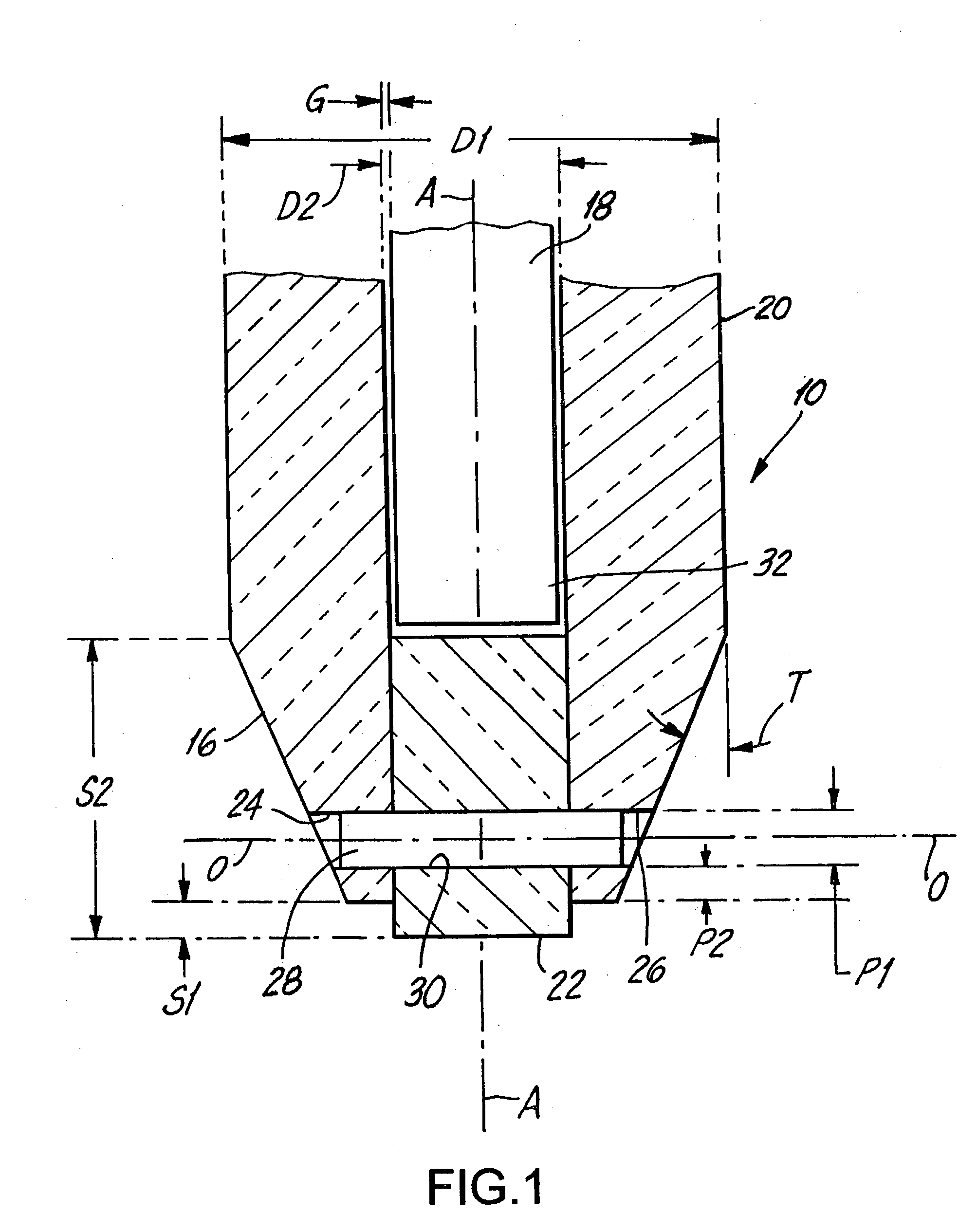
D1 (O.D. of tube 20 above tapered portion) 60 to 200 D2 (I.D. of tube 20) 20 to 75 S1 (axial length of exposed end of plug 22) 10 S2 (axial length of plug 22) (axial length of tapered portion + S1) P1 (diameter of pin 28) 10 to 16 P2 (axial spacing between bottom of pin 10 bore 30 and distal end of tube 20) T 24 to 27