Ejector type refrigerating cycle
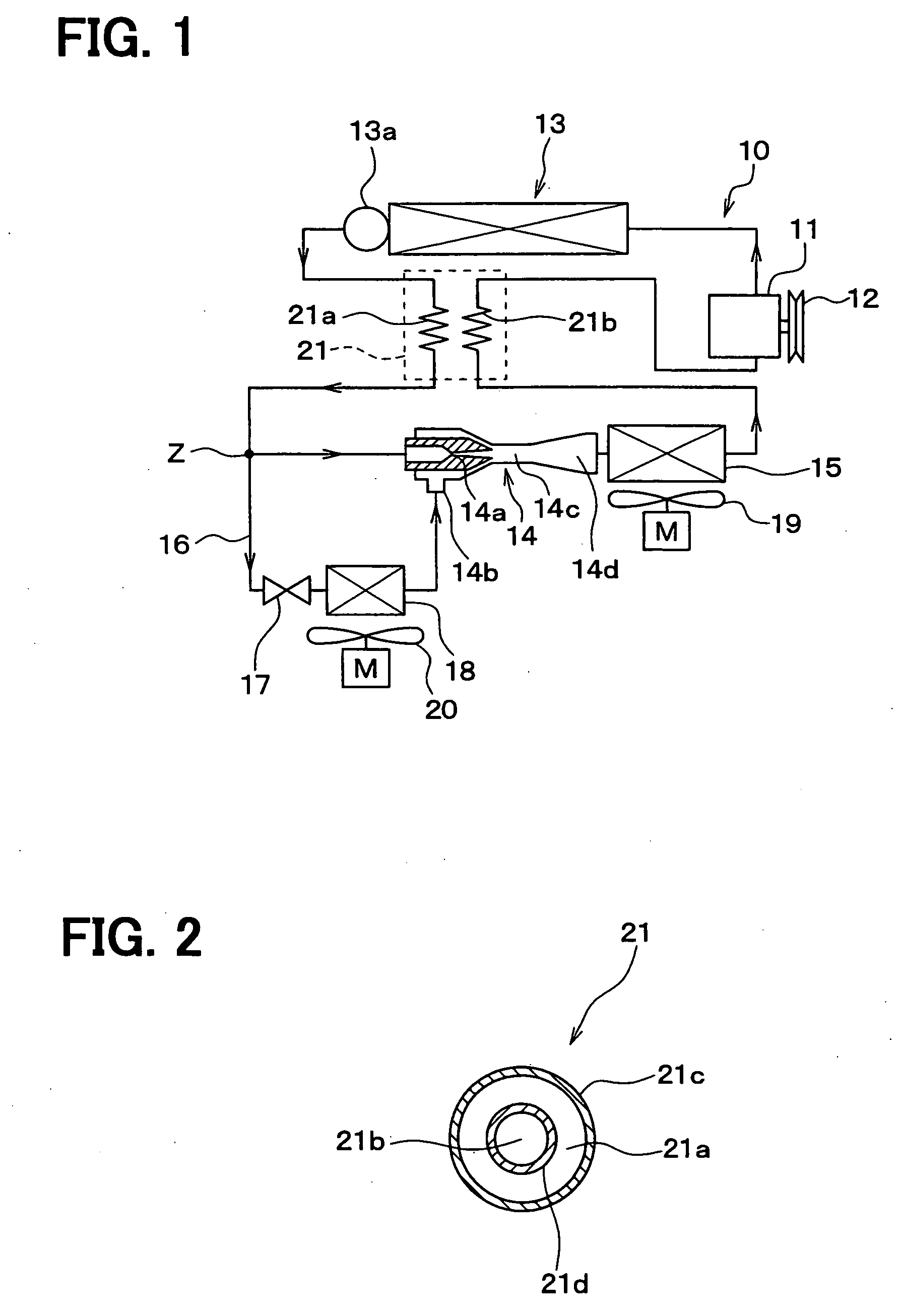
This application is based on Japanese Patent Applications Nos. 2005-105992 filed on Apr. 1, 2005, 2005-195105 filed on Jul. 4, 2005 and 2006-36532 filed on Feb. 14, 2006, the disclosures of which are incorporated herein by reference. The present invention relates to an ejector type refrigerating cycle having an ejector for depressurizing and circulating refrigerant, multiple vaporizing devices, and an internal heat exchanger. The present invention is preferably applied to a refrigerating cycle for an air conditioning apparatus and a refrigerating apparatus. An ejector type refrigerating cycle is proposed, for example as disclosed in Japanese Patent No. 3322263, in which an ejector is used as a means for depressurizing and circulating refrigerant in the refrigerating cycle of a gas compression type. According to the above prior art (JP Pat. No. 3322263), as shown in In the above ejector type refrigerating cycle, a gas phase refrigerant discharged from the second vaporizing device 62 is sucked into the ejector 14 by pressure decrease caused by jet flow at expansion of the refrigerant, and speed energy is converted into pressure energy by a defusing portion (a pressure increasing portion) 14 Heat absorbing operation (cooling operation) can be carried out by the two vaporizing devices 61 and 62 for independent two spaces or one common space. It is further disclosed in the above prior art that, according to the ejector type refrigerating cycle, only one vaporizing device 62 is arranged between the refrigerant outlet side of the gas-liquid separator 63 and the refrigerant suction port 14 It is, however, a problem in the ejector type refrigerating cycle of the above prior art that flow amounts of the refrigerant to the respective (first and second) vaporizing devices 61 and 62 are not easily adjusted, because the respective flow amounts of the refrigerant to the first and second vaporizing devices 61 and 62 must be adjusted by the one ejector 14, whereas the operation (function) of the ejector 14 for circulating the refrigerant (suck-in operation of the gas phase refrigerant) is performed at the same time. Furthermore, in a low load operation, in which a thermal load for the cycle is small, pressure difference between high-pressure side and low pressure side of the refrigerant in the cycle becomes smaller, and input energy of the refrigerant to the ejector is correspondingly small. As a consequence, the refrigerant suck-in performance is decreased at the ejector 14, the flow amount of the refrigerant passing through the second vaporizing device 62 is thereby decreased. This results in another problem that the performance for the cooling operation at the second vaporizing device 62 is decreased. This problem also occurs in the ejector type refrigerating cycle having the internal heat exchanger, which is disclosed in the drawings 34 to 38 of the above prior art (JP Pat. No. 3322263). The present invention is made in view of the foregoing problems, and has an object to provide an ejector type refrigerating cycle having multiple vaporizing devices, according to which flow amounts of the refrigerant to the respective vaporizing devices can be easily adjusted. It is another object of the present invention to provide an ejector type refrigerating cycle, in which high performance of the cooling operation at a second vaporizing device, which is connected to a refrigerant suction port of an ejector, can be realized. It is a further object of the present invention to provide an ejector type refrigerating cycle having an internal heat exchanger, in which performance of the cooling operation can be improved. According to a feature of the present invention, an ejector type refrigerating cycle comprises a compressor (11) for sucking refrigerant and compressing the same, and a heat radiating device (13, 13 An ejector (14) is provided in the refrigerating cycle, which has a nozzle portion (14 The refrigerating cycle further comprises a first vaporizing device (15) for evaporating the refrigerant from the ejector (14) to perform a cooling operation, a first bypass passage (16) bifurcated at an inlet side (Z) of the ejector (14) for supplying a part of the refrigerant from the heat radiating device (13, 13 According to the above feature, the refrigerant can be introduced into both of the first and second vaporizing devices (15, 18) at the same time, in the above ejector type refrigerating cycle in which an operation of high efficiency is achieved by reducing driving force for the compressor. Heat absorbing operation can be simultaneously performed in an intended space (or spaces) for cooling operation by the first and second vaporizing devices (15, 18). Furthermore, the refrigerant flow amount for the first vaporizing device (15) can be controlled by a restriction characteristic of the ejector (14). The refrigerant flow amount to the second vaporizing device (18) can be independently adjusted by the first restricting device (17) provided in the first bypass passage (16). Accordingly, the respective refrigerant flow amounts for the first and second vaporizing devices (15, 18) can be independently adjusted in accordance with thermal loads for the vaporizing devices. Since the first bypass passage (16) supplies the refrigerant bifurcated at the inlet side (Z) of the ejector (14) to the suction port (14 Furthermore, since the internal heat exchanger (21, 211, 212) is provided for the heat exchange between the low-pressure refrigerant in the inlet side of the compressor (11) and the high-pressure refrigerant in the outlet side of the compressor (11), the enthalpy of the high-pressure refrigerant at the outlet side of the heat radiating device (13, 13 The high-pressure refrigerant in the outlet side of the compressor (11) is meant to include the refrigerant in the refrigerant passage from the outlet side of the compressor (11) to the outlet side of the heat radiating device (13, 13 According to another feature of the present invention, an ejector type refrigerating cycle comprises a compressor (11) for sucking refrigerant and compressing the same, and a heat radiating device (13) for radiating heat from high-pressure refrigerant pumped out from the compressor (11). An expansion valve (30) is provided in a refrigerant passage (31) on an outlet side of the heat radiating device (13) for controlling condition of low-pressure refrigerant at the inlet side of the compressor (11) by adjusting a passage opening area of the refrigerant passage (31). An ejector (14) is also provided in the refrigerating, wherein the ejector (14) comprises a nozzle portion (14 The refrigerating cycle further comprises a first vaporizing device (15) for evaporating the refrigerant from the ejector (14) to perform a cooling operation, a bypass passage (16) bifurcated at an inlet side (Z) of the ejector (14) for supplying a part of the refrigerant from the expansion valve (30) to the suction port (14 According to the above feature, the second vaporizing device (18) provided in the suction port side of the ejector (14) is arranged in the bypass passage (16) bifurcated from the inlet side of the ejector (14), and the high-pressure refrigerant at the inlet side of the expansion valve (30) or the inter-mediate pressure refrigerant at the outlet side of the expansion valve (30) is cooled down in the internal heat exchanger (21). The enthalpy of the refrigerant is thereby reduced, so that the cooling capability at the first and second vaporizing devices (15, 18) can be likewise improved. In addition, the condition of the low-pressure refrigerant at the inlet side of the compressor (11) is controlled by adjusting, by the expansion valve (30), the passage opening area of the refrigerant passage (31) at the outlet side of the heat radiating device (13, 13 According to a further feature of the present invention, an ejector type refrigerating cycle has first and second refrigerating cycles. The first refrigerating circuit includes; a compressor (11) for compressing gas phase refrigerant and pumping out compressed high-pressure refrigerant; a heat radiating device (13) connected to an outlet side of the compressor (11) for cooling down the high-pressure refrigerant; an ejector (14) having an inlet port, an outlet port (14 The second refrigerating circuit includes; the compressor (11); the heat radiating device (13); a bypass passage (16) bifurcated from the inlet side of the ejector (14) and connected to the suction port (14 The ejector type refrigerating cycle further comprises an internal heat exchanger (21, 211, 212) having high-pressure side and low-pressure side refrigerant passages (21 The above and other objects, features and advantages of the present invention will become more apparent from the following detailed description made with reference to the accompanying drawing. In the drawing: FIGS. 4 to 8 are schematic diagrams, respectively showing an ejector type refrigerating cycle according to second to sixth embodiments; FIGS. 10 to 19 are schematic diagrams, respectively showing an ejector type refrigerating cycle according to seventh to sixteenth embodiments; and Any type of compressor can be used as the compressor 11, for example, a capacitor variable type compressor which can adjust refrigerant discharge performance depending on variation of the discharge amount, or a fixed capacitor type compressor which can adjust refrigerant discharge performance by changing an operating rate thereof with ON-OFF of the electromagnetic clutch 12. In the case that an electrically operated compressor is used, the refrigerant discharge performance can be adjusted by controlling rotational speed of an electric motor. A heat radiating device (condenser) 13 is connected to a discharge side (outlet side) of the compressor 11. The heat radiating device 13 carries out heat exchange between high-pressure refrigerant discharged from the compressor 11 and outside air (the air outside the vehicle) brown by a cooling fan (not shown), to cool down the high-pressure refrigerant. Fluorocarbon gas, hydrocarbon gas and the like, high pressure of which does not exceed its critical pressure, is used as the refrigerant for the refrigerating cycle 10, wherein a sub-critical cycle of gas compression type is formed. The heat radiating device 13 is, therefore, operated as a condenser for condensing the refrigerant. A receiver 13 Another well known heat exchanger can be used as the heat radiating device 13. Namely, a heat exchanger for condensing the refrigerant can be provided at an upstream side of the refrigerant flow, and the receiver 13 A high-pressure side refrigerant passage 21 Various kinds of structures can be used as a structure for the internal heat exchanger 21. According to the embodiment, a double pipe structure is used for the internal heat exchanger 21, as shown in An ejector 14 is arranged at an outlet side of the high-pressure side refrigerant passage 21 The ejector 14 comprises a nozzle portion 14 A mixing portion 14 A refrigerant bypass passage 16 is bifurcated from a bifurcating point Z (between the heat radiating device 13 and an inlet port of the ejector 14), and its downstream end is connected to the suction port 14 A restricting device (e.g. a fixed orifice) 17 is provided in the bypass passage 16 and the second vaporizing device 18 is arranged at a downstream side of the restricting device 17. The restricting device 17 is formed by a fixed restriction valve, such as a capillary tube, or an orifice, and operates as a depressurizing means for adjusting the refrigerant flow amount to the second vaporizing device 18. An electrically driven valve device can be used for the restriction device 17, so that a valve opening degree (a passage opening area) can be adjusted by an electromagnetic actuator. In the above first embodiment, a first refrigerating circuit is formed by the compressor 11, the heat radiating device 13, the high-pressure side refrigerant passage 21 According to the embodiment, the first vaporizing device 15 is used as an evaporator for performing an air-conditioning operation for an automotive passenger room, wherein air blown by an electrical air blowing device 19 is cooled down by the first vaporizing device 15 and the cooled air is blown into the automotive passenger room. The second vaporizing device 18, according to the embodiment, is used for cooling an automotive refrigerating apparatus, wherein the air of the refrigerating apparatus blown by an electrical air blowing device 20 is cooled down by the second vaporizing device 18 and the cooled air is blown (circulated) into the refrigerating apparatus to cool the inside thereof. An operation of the first embodiment will be explained. When the compressor 11 is driven by the automotive engine, the gas phase high-temperature and high-pressure refrigerant discharged from the compressor 11 flows into the heat radiating device 13, at which the gas phase refrigerant of the high-temperature and high-pressure is cooled down by the air and condensed. The condensed high-pressure refrigerant from the heat radiating device 13 flows into the receiver 13 The liquid phase refrigerant flows out from the receiver 13 The super cooled high-pressure refrigerant is bifurcated at the bifurcating point Z, being separated into the refrigerant flow to the ejector 14 and the refrigerant flow to the bypass passage 16. The refrigerant flowing into the ejector 14 is depressurized and expanded at the nozzle portion 14 The refrigerant ejected from the nozzle portion 14 The refrigerant flows out from the defusing portion 14 The refrigerant flowing into the bypass passage 16 is depressurized by the restricting device 17, so that the refrigerant is changed to the low-pressure refrigerant. The low-pressure refrigerant flows into the second vaporizing device 18, in which the low-pressure refrigerant will be evaporated by absorbing the heat from the air blown by the electrical air blowing device 20. The gas phase refrigerant from the second vaporizing device 18 is sucked into the ejector 14 through the suction port 14 According to the embodiment, as described above, the refrigerant at the downstream side (the outlet port) of the defusing portion 14 In the above operation, the refrigerant pressure of the evaporation in the first vaporizing device 15 corresponds to the refrigerant pressure increased at the defusing portion 14 As above, the refrigerant evaporation pressure (the refrigerant evaporation temperature) in the second vaporizing device 18 can be made lower than the refrigerant evaporation pressure (the refrigerant evaporation temperature) in the first vaporizing device 15. Since, according to the embodiment, the first vaporizing device 15 is used for the cooling operation of the passenger room, whereas the second vaporizing device 18 is used for the cooling operation of the refrigerating apparatus, the temperature in the refrigerating apparatus can be controlled at a lower value than that for the passenger room. In other words, the cooling operations for the passenger room and the refrigerating apparatus can be independently controlled at two different (higher and lower) temperatures. Furthermore, the refrigerant flow amount to the second vaporizing device 18 can be independently controlled by the restricting device 17, without depending on the function of the ejector 14. The refrigerant flow amount to the first vaporizing device 15 can be also adjusted by the control of the refrigerant discharge performance of the compressor 11 and the restricting characteristic of the ejector 14. As a result, the refrigerant flow amounts to the respective first and second vaporizing devices 15 and 18 can be easily controlled depending on the respective thermal loads. In the above operation, the refrigerant pressure is increased at the defusing portion 14 In an operational condition, in which the thermal load is small in the cycle, the refrigerant pressure difference in the cycle becomes smaller, and the input energy of the refrigerant to the ejector 14 becomes correspondingly smaller. According to the refrigerating cycle of the above mentioned prior art (JP Pat. No. 3322263), as shown in According to the present invention, however, the high-pressure refrigerant is bifurcated at the upstream side (the bifurcating point Z) of the ejector 14, and the bifurcated refrigerant flows through the bypass passage 16 and sucked into the suction port 14 The refrigerant can be, therefore, supplied to the second vaporizing device 18 not only by the suck-in operation of the refrigerant at the ejector 14 from the bypass passage 16, but also by use of the performance of the refrigerant suction and refrigerant discharge of the compressor 11. Accordingly, even when the input energy of the refrigerant to the ejector 14 is reduced, and the suck-in operation of the refrigerant at the ejector 14 is thereby reduced, the decrease of the refrigerant flow to the second vaporizing device 18 can be suppressed to a smaller amount, in comparison with the case of the above mentioned prior art (JP Pat. No. 3322263). Even in the operational condition, in which the thermal load is small in the cycle, the necessary performance of the cooling operation by the second vaporizing device 18 can be easily achieved. Furthermore, since the high-pressure refrigerant at the outlet side of the heat radiating device 13, more specifically at the outlet side of the receiver 13 The refrigerating cycle with the internal heat exchanger 21 generally has a disadvantage that the temperature of the discharged refrigerant at the compressor 11 would become higher as a result that the super heat of the refrigerant at the inlet side of the compressor is increased. According to the embodiment of the present invention, however, the increase of the temperature of the discharged refrigerant from the compressor can be avoided by incorporating the internal heat exchanger 21 into the ejector type refrigerating cycle. This will be explained with reference to a Molier diagram shown in In the comparison example, a point “a” shows a condition of the refrigerant which has absorbed the heat through the heat exchange in the internal heat exchanger 21 (heated to the point “a”) and will be sucked into the compressor. When the refrigerant is compressed to such a discharge pressure, which is determined by the cycle balance, the condition of the refrigerant moves from the point “a” to a point “b”. As a result, the temperature of the refrigerant discharged from the compressor is increased to such a temperature, which is determined by the point “b”. In According to the ejector type refrigerating cycle of the present invention, the evaporation pressure of the refrigerant at the first vaporizing device 15 becomes higher than that of the second vaporizing device 18, by a predetermined pressure increase amount “c”, due to a pressure increasing effect at the defusing portion 14 The pressure of the refrigerant to be sucked into the compressor 11 is thereby increased by the above pressure increase amount “c”, so that a compression ratio at the compressor 11 can be made smaller. As a result, the condition of the discharged refrigerant from the compressor moves to a point “d”. As shown in the drawing, when compared with the comparison example (the point “b”), the point “d”, is moved to the lower temperature side of the isothermal line, so that the temperature of the discharged refrigerant from the compressor can be made lower than that of the comparison example. According to the embodiment shown in Accordingly, an assembling and mounting process of the refrigerating cycle into the vehicle can be made simpler and easier by use of the internal heat exchanger 21 having the double pipe structure. In the above first embodiment, the high-pressure side refrigerant passage 21 According to the second embodiment, only the high-pressure refrigerant bifurcated to the bypass passage 16 is cooled down by the internal heat exchanger 21. The super cooling degree of the refrigerant is thereby increased, and the enthalpy of the refrigerant at the inlet side of the second vaporizing device 18 is reduced. On the other hand, since the high-pressure refrigerant passing through the ejector 14 is not cooled down by the internal heat exchanger 21, the enthalpy of the refrigerant at the outlet side of the receiver 13 The ejector type refrigerating cycle can be operated without decreasing the pressure increase amount at the defusing portion 14 A restricting device 23 and a third vaporizing device 24 are provided in the second bypass passage 22. The restricting device 23 is formed by a fixed restriction valve, such as a capillary tube, or an orifice, and operates as a depressurizing means for adjusting the refrigerant flow amount to the third vaporizing device 24. An electrically driven valve device can be used for the restriction device 23, so that a valve opening degree (a passage opening area) can be adjusted by an electromagnetic actuator. Air in a space, for which cooling operation is carried out, is blown to the third vaporizing device 24 by an air blowing device 25. An outlet side of the third vaporizing device 24 is linked up with the outlet side of the first vaporizing device 15 and connected to the inlet side of the low-pressure side refrigerant passage 21 In the above third embodiment, the first and second refrigerating circuits are formed in the same manner to the first embodiment. A third refrigerating circuit is formed by the compressor 11, the heat radiating device 13, the high-pressure side refrigerant passage 21 According to the third embodiment, an intended space for the cooling operation by the first vaporizing device 15 is, for example, a front seat passenger room, whereas an intended space for the cooling operation by the third vaporizing device 24 is a rear seat passenger room. Accordingly, the front and rear seat passenger rooms can be simultaneously and independently cooled by the respective first and third vaporizing devices 15 and 24. In the case that the vehicle refrigerating apparatus is selected as an intended space for the cooling operation by the second vaporizing device 18, as in the same manner to the first embodiment, the refrigerating apparatus can be also simultaneously cooled together with the cooling operation for the front and rear seat passenger rooms. When the internal heat exchanger 21 is formed by the double pipe structure in the second and third embodiments, the assembling and mounting process of the refrigerating cycle to the vehicle can be made easier, as in the same manner to the first embodiment. In the first embodiment, the first and second vaporizing devices 15 and 18 are independently constructed to respectively perform the cooling operation. According to a fourth embodiment, as shown in According to such structure, the first and second vaporizing devices 15 and 18 can be handled as one unit, so that an assembling process of the first and second vaporizing devices 15 and 18 into the casing 26 can be made simpler. The vehicle passenger room or the vehicle refrigerating apparatus is selected as an intended common space for the cooling operation by the first and second vaporizing devices 15 and 18. According to the fourth embodiment, therefore, a common air blowing device 27 is provided for blowing the air to the first and second vaporizing devices 15 and 18. In this embodiment, the first vaporizing device 15, in which the evaporation temperature of the refrigerant is higher, is arranged at an upstream side of the blowing air (indicated by an arrow “D”) from the air blowing device 27, whereas the second vaporizing device 18, in which the evaporation temperature of the refrigerant is lower, is arranged at a downstream side of the blowing air (indicated by the arrow “D”). With such a structure, a temperature difference can be realized between the evaporation temperature of the refrigerant at the first vaporizing device 15 and the blowing air and between the evaporation temperature of the refrigerant at the second vaporizing device 18 and the blowing air. The first and second vaporizing devices 15 and 18 can effectively bring out the cooling capability. The cooling capability by the first and second vaporizing devices 15 and 18 to the common intended space for the cooling operation can be effectively improved in its combination. In the above fourth embodiment, parts for the vaporizing devices 15 and 18, such as tubes, fins, tanks and so on, are preferably formed from metal material, such as aluminum or the like, and those parts are integrally brazed to each other, so that the vaporizing devices can be manufactured with high productivity. In the above first to fourth embodiments, the receiver 13 The accumulator 28 separates the refrigerant into the gas phase and liquid phase refrigerants by use of difference of the refrigerant density, and accumulate the liquid phase refrigerant at its bottom portion and sends out the gas phase refrigerant to the low-pressure side refrigerant passage 21 In a sixth embodiment, as shown in In the above fifth and sixth embodiments ( (Variations for the Refrigerant Passages of the Internal Heat Exchanger 21, in the First to Sixth Embodiments) The high-pressure side and low-pressure side refrigerant passages 21 More specifically, the high-pressure side refrigerant passage 21 On the other hand, the low-pressure side refrigerant passage 21 Accordingly, there are seven different positions for the high-pressure side refrigerant passage 21 In the above first to sixth embodiments and in the variations of the refrigerant passages of the internal heat exchanger shown in In the above seventh embodiment, the heat radiating device is divided into the first and second heat radiating devices 13 Since the second part 21 The internal heat exchanger 21 is arranged such that the refrigerant in the low-pressure side refrigerant passage 21 As above, the refrigerant flow in the first and second parts 21 In the case that an electrically driven compressor is used for the compressor 11, dew drops are likely to be produced at a surface of the refrigerant suction side pipe, because temperature at such surface portion becomes low. As a result, an electrical trouble, such as a short-circuit in electrical circuit portions, may be easily caused by water component of the dew drops. According to the seventh embodiment, the first part 21 Accordingly, in the heat exchange between the first part 21 In the above seventh embodiment, multiple parts 21 According to the above seventh embodiment, the heat radiating device is divided into the first heat radiating device 13 More specifically, the second bypass passage 22 is provided in parallel with the first bypass passage 16, as in the same manner to the third embodiment of The first internal heat exchanger 211 is constructed that the heat exchange is carried out between a high-pressure side refrigerant passage 211 On the other hand, the second internal heat exchanger 212 is constructed that the heat exchange is carried out between a high-pressure side refrigerant passage 212 An outlet side of the low-pressure side refrigerant passage 212 The high-pressure side refrigerant passage 211 According to the above eighth embodiment, the first and second internal heat exchangers 211 and 212 are respectively provided in the first and second bypass passages 16 and 22. This means that the heat exchange amount in the first internal heat exchanger 211 can be independently designed so that the cooling capability can be effectively brought out at the second vaporizing device 18. And in the same manner to the above, the heat exchange amount in the second internal heat exchanger 212 can be independently designed so that the cooling capability can be effectively brought out at the third vaporizing device 24. In the above seventh and eighth embodiments, the intended spaces for the cooling operations by the first and second vaporizing devices 15 and 18 can be independent two spaces, or can be single common space. For example, the former case corresponds to the first to third embodiments ( The expansion valve 30 is arranged in a refrigerant passage 31, which is provided between the high-pressure side refrigerant passage 21 The expansion valve 30, therefore, comprises a valve body (not shown) for adjusting a valve opening degree (the opening area of the refrigerant passage) for the refrigerant passage 31, and a valve driving mechanism 30 The valve driving mechanism 30 Characteristic features of the ninth embodiment will be explained. The high-pressure refrigerant from the heat radiating device 13 is depressurized (first depressurization) when the refrigerant passes through the expansion valve 30, so that the refrigerant pressure is decreased to a predetermined intermediate pressure. The refrigerant of the intermediate pressure is bifurcated at the bifurcating point Z, so that it is divided into the refrigerant flow to the ejector 14 and the refrigerant flow to the bypass passage 16. Those refrigerants are further depressurized (second depressurization) by the ejector 14 and the restricting device 17, respectively, and the refrigerant pressure is decreased to a predetermined low pressure. Since the temperature dependent type expansion valve 30 is provided in the refrigerant passage 31 at the upstream side of the bifurcating point Z, the total refrigerant flow amount to the first and second vaporizing devices 15 and 18 can be properly controlled by adjusting the valve opening degree (the opening area of the passage) for the refrigerant passage 31, so that the super heat degree of the refrigerant at the outlet side of the first vaporizing device 15 controlled at the predetermined value. Since the refrigerant from the first vaporizing device 15 is sucked into the compressor 11, after the refrigerant has absorbed the heat when passing through the low-pressure side refrigerant passage 21 Furthermore, the refrigerant flow amount can be controlled so that almost all the liquid phase refrigerant is evaporated in the first vaporizing device 15, by controlling the refrigerant condition immediately from the first vaporizing device 15 to be the condition equal or close to the saturated gas having the super heat degree of 0° C. As above, the heat absorbing operation of the latent heat can be carried out at the whole area of the first vaporizing device 15 through the evaporation of the liquid phase refrigerant, without causing the return of the liquid phase refrigerant to the compressor 11. As a result, high cooling capability can be brought out at the first vaporizing device 15. In the ninth embodiment, the super cooling degree of the high-pressure refrigerant at the upstream side of the expansion valve 30 can be also increased by the internal heat exchanger 21, and the enthalpy difference of the refrigerant between the inlet and outlet sides of the first and second vaporizing devices 15 and 18 can be thereby increased, so that the cooling capability at the vaporizing devices 15 and 18 is enhanced. The temperature increase of the refrigerant at the outlet side of the compressor 11, which might occur in the ejector type refrigerating cycle, as explained in Since the low-pressure side refrigerant passage 21 The expansion valve 30 may not be necessarily composed of a pure mechanical structure. Instead, an electrical expansion valve can be used as the expansion valve 30, which electrically adjusts the valve opening degree (the opening area of the refrigerant passage) in accordance with detected electrical signals from a refrigerant temperature sensor and a refrigerant pressure sensor. In the above ninth embodiment, the temperature dependent type expansion valve 30 is provided at the downstream side of the high-pressure side passage 21 More specifically, the intermediate-pressure side refrigerant passage 21 Since the intermediate-pressure side refrigerant passage 21 In the case that the intermediate-pressure refrigerant flowing into the nozzle portion 14 As a result, when the enthalpy of the intermediate-pressure refrigerant flowing into the nozzle portion 14 According to the eleventh embodiment, however, only the refrigerant in the bypass passage 16 is heat exchanged, while the refrigerant of the intermediate-pressure is introduced directly from the expansion valve 30 into the nozzle portion 14 The refrigerant of the intermediate-pressure in the bypass passage 16 is super cooled by the internal heat exchange (heat radiation) to decrease its enthalpy, so that the cooling capability at the second vaporizing device 18 can be improved. The high-pressure refrigerant from the heat radiating device 13 is depressurized by the primary depressurizing operation at the expansion valve 30 to the gas-liquid phase refrigerant of the intermediate-pressure. According to the above eleventh embodiment ( According to the thirteenth embodiment, the refrigerant of the intermediate-pressure is liquefied by heat radiation to the low-pressure refrigerant at the refrigerant passage 21 The unsteady flow of the air bubbles can be suppressed in the restricting device 17 and the nozzle portion 14 Namely, the capillary tube 17 is formed as not only the restriction device in the bypass passage 16 but also a part (the refrigerant passage 21 More specifically, the internal heat exchanger 21 of the double pipe structure is constructed such that the capillary tube 17 is formed as the inside pipe and a refrigerant passage from the first vaporizing device 15 (i.e. a refrigerant passage for the compressor inlet side) is formed as the outside pipe. The inside heat exchange 21 may be alternatively constructed such that the capillary tube 17 and the refrigerant passage from the first vaporizing device 15 (i.e. a refrigerant passage for the compressor inlet side) are connected with each other, so that the heat conduction between them can be performed in a good condition. A part 17 According to the fifteenth embodiment, the refrigerant of the intermediate-pressure from the expansion valve 30 is depressurized by the capillary tube 17 and at the same time the heat can be radiated to the low-pressure refrigerant in the inlet side of the compressor 11. According to the eleventh embodiment of Since the refrigerant density largely varies from the super cooled liquid phase condition to the gas-liquid condition, it is difficult to perform an appropriate depressurizing characteristic for both cases of the super cooled liquid phase refrigerant and the gas-liquid refrigerant, by means of the restricting device, such as the capillary tube 17, which has a fixed restriction. According to the fifteenth embodiment, however, the gas-liquid phase refrigerant of the intermediate-pressure from the expansion valve 30 is depressurized by the capillary tube 17 and at the same time the heat is radiated to the low-pressure refrigerant in the inlet side of the compressor 11. Namely, while the condition of the gas-liquid phase refrigerant is maintained in the capillary tube 17, the depressurizing operation as well as the heat radiating operation can be carried out. Therefore, it is easier to design the refrigerating cycle, so that the depressurizing characteristic of the capillary tube 17 can be adjusted to an intended depressurizing characteristic (the intended depressurizing amount). In the case that the whole length of the capillary tube 17 was constructed as the refrigerant passage of the internal heat exchanger 21, the refrigerant temperature would be decreased at a certain downstream portion of the capillary tube 17, to become lower than that of the low-pressure refrigerant in the compressor inlet side. In such a case, the heat could be reversely absorbed from the low-pressure refrigerant in the compressor inlet side. According to the fifteenth embodiment, however, the part 17 The present invention should not be limited to the above explained embodiments, but various kinds of modifications are possible as below. (1) In the above embodiments, electrically controlled valves, such as electromagnetic valves, may be provided in the refrigerant passage for the first vaporizing device 15, the first bypass passage 16 and the second bypass passage 22 for respectively controlling the passage areas thereof, so that the refrigerant flow to the first, second and/or third vaporizing devices 15, 18, 24 can be freely selected. In such a modification, the electrically controlled valves may be used for the restricting devices 17, 23 in the first and second bypass passages 16, 22, so that those restricting devices can bring out not only the restricting operation but also an opening-closing operation of the refrigerant passages. (2) In the refrigerating cycles shown in the first to fourth embodiments, in which the receiver 13 (3) In the above embodiments, the sub-critical cycle of the gas compression type is formed by the refrigerant, such as fluorocarbon gas, hydrocarbon gas and the like, high pressure of which does not exceed its critical pressure. The present invention can be also applied to a super critical cycle of the gas compression type, which is operated with the refrigerant, such as carbon dioxide (CO2), high pressure of which exceeds its critical pressure. In the super critical cycle, the heat of the refrigerant from the compressor is radiated at the heat radiating device 13 in the super critical condition, but the refrigerant is not condensed. The receiver 13 In case of the super critical cycle, therefore, the accumulator may be provided at the outlet side of the first vaporizing device 15 for operating as the gas-liquid separator in the low-pressure side, as shown in In the above embodiments, the ejector 14 of a fixed type, in which the nozzle portion 14 As an example of the variable type ejector, it may be constructed such that a movable needle is inserted into a passage portion of the nozzle portion and a relative position of the needle with respect to the nozzle portion is varied by an electrical actuator, so that the passage area at the nozzle portion can be adjusted. The refrigerant pressure at the high-pressure side can be controlled in the sub-critical and super critical cycles by adjusting the passage area of the nozzle portion of the variable type ejector. (5) In the first embodiment and other embodiment, the present invention is applied to the refrigerating cycle, by which the air conditioning operation for the vehicle passenger room as well as the cooling operation for the vehicle refrigerating apparatus are performed. However, both of the first vaporizing device 15, the refrigerant evaporation temperature in which is on the high temperature side, and the second vaporizing device 18, the refrigerant evaporation temperature in which is on the low temperature side, can be used for the air conditioning operation for the vehicle passenger room, but for the different spaces (for example, the front seat space and the rear seat space). (6) Furthermore, both of the first vaporizing device 15, the refrigerant evaporation temperature in which is on the high temperature side, and the second vaporizing device 18, the refrigerant evaporation temperature in which is on the low temperature side, can be used for the cooling operation for the vehicle refrigerating apparatus. Namely, the first vaporizing device 15, the refrigerant evaporation temperature in which is on the high temperature side, may be used for cooling a chill room, whereas the second vaporizing device 18, the refrigerant evaporation temperature in which is on the low temperature side, may be used for cooling a freezing compartment. An electromagnetic valve may be combined with a fixed restriction to form the restricting devices 17, 23, so that a passage closing operation can be added to the operation for the flow amount control by the fixed restriction. An ejector type refrigerating cycle comprises a compressor, a heat radiating device, an ejector, and a first vaporizing device, which are connected in a circuit to form a refrigerating cycle. A bypass passage is provided between an inlet port and a suction port of the ejector, so that a part of the refrigerant is bifurcated to flow through the bypass passage. A second vaporizing device is provided in the bypass passage. An internal heat exchanger is further provided between an outlet side of the heat radiating device and the inlet side of the ejector, so that the enthalpy of the high-pressure refrigerant from the heat radiating device is reduced, to thereby increase an enthalpy difference between the inlet side and outlet side of the first and second vaporizing devices. As a result, the cooling capability by the both vaporizing devices can be improved. 1. An ejector type refrigerating cycle comprising:
a compressor for sucking refrigerant and compressing the same; a heat radiating device for radiating heat from high-pressure refrigerant pumped out from the compressor; an ejector having a nozzle portion for depressurizing and expanding the refrigerant from the heat radiating device, a suction port for sucking the refrigerant by high speed refrigerant flow ejected from the nozzle portion, and a pressure increasing portion for mixing the high speed refrigerant ejected from the ejector nozzle with the refrigerant sucked from the suction port and for increasing fluid pressure of the refrigerant while converting the speed energy of the refrigerant to pressure energy; a first vaporizing device for evaporating the refrigerant from the ejector to perform a cooling operation; a first bypass passage bifurcated at an inlet side of the ejector for supplying a part of the refrigerant from the heat radiating device to the suction port of the ejector; a first restricting device provided in the first bypass passage for depressurizing the part of the refrigerant from the heat radiating device; a second vaporizing device provided in the first bypass passage at an outlet side of the first restricting device for evaporating the refrigerant to perform a cooling operation; and an internal heat exchanger for carrying out heat exchange between low-pressure refrigerant on an inlet side of the compressor and high-pressure refrigerant on an outlet side of the compressor. 2. An ejector type refrigerating cycle according to a high-pressure side refrigerant passage of the internal heat exchanger is arranged in the first bypass passage at an inlet side of the first restricting device. 3. An ejector type refrigerating cycle according to a second bypass passage bifurcated at the inlet side of the ejector for supplying a part of the refrigerant from the heat radiating device to the inlet side of the compressor; a second restricting device provided in the second bypass passage for depressurizing the part of the refrigerant passing through the second bypass passage; a third vaporizing device provided in the second bypass passage at an outlet side of the second restricting device for evaporating the refrigerant to perform a cooling operation. 4. An ejector type refrigerating cycle according to a low-pressure side refrigerant passage of the internal heat exchanger is arranged in a refrigerant passage at a downstream side of a link-up point of an outlet side of the first vaporizing device and an outlet side of the third vaporizing device. 5. An ejector type refrigerating cycle according to the internal heat exchanger comprises at least first and second heat exchanging devices, a first high-pressure side refrigerant passage is formed in the first heat exchanging device, so that high-pressure refrigerant flowing in the first bypass passage passes through the first high-pressure side refrigerant passage, and a second high-pressure side refrigerant passage is formed in the second heat exchanging device, so that high-pressure refrigerant flowing in the second bypass passage passes through the second high-pressure side refrigerant passage. 6. An ejector type refrigerating cycle according to a gas-liquid separator provided at an outlet side of the first vaporizing device for separating the refrigerant into gas phase and liquid phase refrigerants, wherein the low-pressure side refrigerant passage of the internal heat exchanger is arranged at an outlet side of the gas-liquid separator. 7. An ejector type refrigerating cycle according to at least one of the high-pressure side and low-pressure side refrigerant passages comprises multiple passage portions, which are respectively arranged in different refrigerant passages of the refrigerating cycle. 8. An ejector type refrigerating cycle according to the internal heat exchanger is formed into a double pipe structure having an inside pipe formed in an inside of an outside pipe, the high-pressure side refrigerant passage is formed by one of the passage of the inside pipe and the passage formed between the inside and outside pipes, and the low-pressure side refrigerant passage is formed by the other of the passage of the inside pipe and the passage formed between the inside and outside pipes. 9. An ejector type refrigerating cycle comprising:
a compressor for sucking refrigerant and compressing the same; a heat radiating device for radiating heat from high-pressure refrigerant pumped out from the compressor; an expansion valve provided in a refrigerant passage on an outlet side of the heat radiating device for controlling condition of low-pressure refrigerant at the inlet side of the compressor by adjusting a passage opening area of the refrigerant passage; an ejector having a nozzle portion for depressurizing and expanding the refrigerant from the expansion valve, a suction port for sucking the refrigerant by high speed refrigerant flow ejected from the nozzle portion, and a pressure increasing portion for mixing the high speed refrigerant ejected from the ejector nozzle with the refrigerant sucked from the suction port and for increasing fluid pressure of the refrigerant while converting the speed energy of the refrigerant to pressure energy; a first vaporizing device for evaporating the refrigerant from the ejector to perform a cooling operation; a bypass passage bifurcated at an inlet side of the ejector for supplying a part of the refrigerant from the expansion valve to the suction port of the ejector; a restricting device provided in the bypass passage for depressurizing the part of the refrigerant from the expansion valve; a second vaporizing device provided in the bypass passage at an outlet side of the restricting device for evaporating the refrigerant to perform a cooling operation; and an internal heat exchanger for carrying out heat exchange between low-pressure refrigerant on the inlet side of the compressor and high-pressure refrigerant on an inlet side of the expansion valve, or between the low-pressure refrigerant on the inlet side of the compressor and intermediate-pressure refrigerant on an outlet side of the expansion valve. 10. An ejector type refrigerating cycle according to the internal heat exchanger carries out the heat exchange between a high-pressure side refrigerant passage provided at the inlet side of the expansion valve and the low-pressure side refrigerant passage provided at the inlet side of the compressor. 11. An ejector type refrigerating cycle according to the internal heat exchanger carries out the heat exchange between an intermediate-pressure side refrigerant passage provided in the bypass passage at the inlet side of the restricting device and the low-pressure side refrigerant passage provided at the inlet side of the compressor. 12. An ejector type refrigerating cycle according to the internal heat exchanger carries out the heat exchange between an intermediate-pressure side refrigerant passage provided between the outlet side of the expansion valve and a bifurcating point of the bypass passage and the low-pressure side refrigerant passage provided at the inlet side of the compressor. 13. An ejector type refrigerating cycle according to the restricting device is formed by a capillary tube, and the heat exchange of the internal heat exchanger is carried out between the capillary tube and the low-pressure side refrigerant passage on the inlet side of the compressor. 14. An ejector type refrigerating cycle according to the expansion valve controls the condition of the low-pressure refrigerant between the outlet side of the first vaporizing device and the low-pressure side refrigerant passage in accordance with temperature and pressure of such refrigerant. 15. An ejector type refrigerating cycle according to the first and second vaporizing devices are integrally formed into one unit. 16. An ejector type refrigerating cycle comprising:
a first refrigerating circuit including;
a compressor for compressing gas phase refrigerant and pumping out compressed high-pressure refrigerant; a heat radiating device connected to an outlet side of the compressor for cooling down the high-pressure refrigerant; an ejector having an inlet port, an outlet port and a suction port, in which the inlet port of the ejector is connected to an outlet side of the heat radiating device, the ejector further having a nozzle portion for depressurizing and expanding the refrigerant from the heat radiating device, wherein the outlet port mixes the high speed refrigerant ejected from the nozzle portion with the refrigerant sucked from the suction port and increases fluid pressure of the refrigerant while converting the speed energy of the refrigerant to the pressure energy; and a first vaporizing device connected at its inlet side to the outlet port of the ejector, and at its outlet side to the inlet side of the compressor; a second refrigerating circuit including;
the compressor; the heat radiating device; a bypass passage bifurcated from the inlet side of the ejector and connected to the suction port of the ejector; a second vaporizing device provided in the bypass passage; and the first vaporizing device; and an internal heat exchanger having high-pressure side and low-pressure side refrigerant passages, wherein the high-pressure side refrigerant passage is provided between the outlet side of the heat radiating device and the inlet port of the ejector, and/or between the outlet side of the heat radiating device and the inlet side of the second vaporizing device, whereas the low-pressure side refrigerant passage is provided between the outlet side of the first vaporizing device and the inlet side of the compressor. 17. An ejector type refrigerating cycle according to a third refrigerating circuit including;
the compressor; the heat radiating device; a second bypass passage bifurcated from the inlet side of the ejector and connected to the outlet side of the first vaporizing device; and a third vaporizing device provided in the second bypass passage. 18. An ejector type refrigerating cycle according to a gas-liquid separator provided at the outlet side of the heat radiating device. 19. An ejector type refrigerating cycle according to a restricting device provided in the bypass passage at the inlet side of the second vaporizing device. 20. An ejector type refrigerating cycle according to a restricting device provided in the second bypass passage at the inlet side of the third vaporizing device. 21. An ejector type refrigerating cycle according to an accumulator provided between the outlet side of the first vaporizing device and the low-pressure side refrigerant passage of the internal heat exchanger. 22. An ejector type refrigerating cycle according to the heat radiating device comprises first and second heat radiating portions, the high-pressure side refrigerant passage of the internal heat exchanger comprises first and second refrigerant passage portions, the first refrigerating circuit is formed by the compressor, the first heat radiating portion, the first refrigerant passage portion of the internal heat exchanger, the second heat radiating portion, the inlet and outlet ports of the ejector, the first vaporizing device, an accumulator, and the low-pressure side refrigerant passage of the internal heat exchanger, and the second refrigerating circuit is formed by the compressor, the first heat radiating portion, the first refrigerant passage portion of the internal heat exchanger, the second heat radiating portion, the second refrigerant passage portion, a restricting device, the second vaporizing device, the suction and outlet ports of the ejector, the first vaporizing device, the accumulator, and the low-pressure side refrigerant passage of the internal heat exchanger. 23. An ejector type refrigerating cycle according to the internal heat exchanger comprises first and second heat exchanging portions, the first refrigerating circuit is formed by the compressor, the heat radiating device, the inlet and outlet ports of the ejector, the first vaporizing device, an accumulator, and the low-pressure side refrigerant passage of the first heat exchanging portion, the second refrigerating circuit is formed by the compressor, the heat radiating device, the high-pressure side refrigerant passage of the first heat exchanging portion, a restricting device, the second vaporizing device, the suction and outlet ports of the ejector, the first vaporizing device, the accumulator, and the low-pressure side refrigerant passage of the first heat exchanging portion, and a third refrigerating circuit is formed by the compressor, the heat radiating device, the high-pressure side refrigerant passage of the second heat exchanging portion, a restricting device, a third vaporizing device and the low-pressure side refrigerant passage of the second heat exchanging portion. 24. An ejector type refrigerating cycle according to an expansion device provided between the outlet side of the high-pressure side refrigerant passage of the internal heat exchanger and the inlet port of the ejector, and between the outlet side of the high-pressure side refrigerant passage of the internal heat exchanger and the inlet side of the second vaporizing device. 25. An ejector type refrigerating cycle comprising:
a first refrigerating circuit including;
a compressor for compressing gas phase refrigerant and pumping out compressed high-pressure refrigerant; a heat radiating device connected to an outlet side of the compressor for cooling down the high-pressure refrigerant; an expansion valve arranged at the outlet side of the heat radiating device for depressurizing the refrigerant from the heat radiating device; an ejector having an inlet port, an outlet port and a suction port, in which the inlet port of the ejector is connected to an outlet side of the expansion valve, the ejector further having a nozzle portion for depressurizing and expanding the refrigerant from the expansion valve, wherein the outlet port mixes the high speed refrigerant ejected from the nozzle portion with the refrigerant sucked from the suction port and increases fluid pressure of the refrigerant while converting the speed energy of the refrigerant to the pressure energy; and a first vaporizing device connected at its inlet side to the outlet port of the ejector, and at its outlet side to the inlet side of the compressor; a second refrigerating circuit including;
the compressor; the heat radiating device; the expansion valve; a bypass passage bifurcated from the inlet side of the ejector and connected to the suction port of the ejector; a second vaporizing device provided in the bypass passage; and the first vaporizing device; and an internal heat exchanger having intermediate-pressure side and low-pressure side refrigerant passages, wherein the intermediate-pressure side refrigerant passage is provided between the outlet side of the expansion valve and the inlet side of the second vaporizing device, whereas the low-pressure side refrigerant passage is provided between the outlet side of the first vaporizing device and the inlet side of the compressor. 26. An ejector type refrigerating cycle comprising:
a first refrigerating circuit including;
a compressor for compressing gas phase refrigerant and pumping out compressed high-pressure refrigerant; a heat radiating device connected to an outlet side of the compressor for cooling down the high-pressure refrigerant; an expansion valve arranged at the outlet side of the heat radiating device for depressurizing the refrigerant from the heat radiating device; an ejector having an inlet port, an outlet port and a suction port, in which the inlet port of the ejector is connected to an outlet side of the expansion valve, the ejector further having a nozzle portion for depressurizing and expanding the refrigerant from the expansion valve, wherein the outlet port mixes the high speed refrigerant ejected from the nozzle portion with the refrigerant sucked from the suction port and increases fluid pressure of the refrigerant while converting the speed energy of the refrigerant to the pressure energy; and a first vaporizing device connected at its inlet side to the outlet port of the ejector, and at its outlet side to the inlet side of the compressor; a second refrigerating circuit including;
the compressor; the heat radiating device; the expansion valve; a bypass passage bifurcated from the inlet side of the ejector and connected to the suction port of the ejector; a second vaporizing device provided in the bypass passage; and the first vaporizing device; and an internal heat exchanger having intermediate-pressure side and low-pressure side refrigerant passages, wherein the intermediate-pressure side refrigerant passage is provided between the outlet side of the expansion valve and the inlet port of the ejector and between the outlet side of the expansion valve and the inlet side of the second vaporizing device, whereas the low-pressure side refrigerant passage is provided between the outlet side of the first vaporizing device and the inlet side of the compressor. 27. An ejector type refrigerating cycle comprising:
a first refrigerating circuit including;
a compressor for compressing gas phase refrigerant and pumping out compressed high-pressure refrigerant; a heat radiating device connected to an outlet side of the compressor for cooling down the high-pressure refrigerant; an expansion valve arranged at the outlet side of the heat radiating device for depressurizing the refrigerant from the heat radiating device; an ejector having an inlet port, an outlet port and a suction port, in which the inlet port of the ejector is connected to an outlet side of the expansion valve, the ejector further having a nozzle portion for depressurizing and expanding the refrigerant from the expansion valve, wherein the outlet port mixes the high speed refrigerant ejected from the nozzle portion with the refrigerant sucked from the suction port and increases fluid pressure of the refrigerant while converting the speed energy of the refrigerant to the pressure energy; and a first vaporizing device connected at its inlet side to the outlet port of the ejector, and at its outlet side to the inlet side of the compressor; a second refrigerating circuit including;
the compressor; the heat radiating device; the expansion valve; a bypass passage bifurcated from the inlet side of the ejector and connected to the suction port of the ejector; a second vaporizing device provided in the bypass passage; and the first vaporizing device; and an internal heat exchanger having intermediate-pressure side and low-pressure side refrigerant passages, wherein the intermediate-pressure side refrigerant passage is provided between the inlet side of the ejector and the inlet side of the second vaporizing device, whereas the low-pressure side refrigerant passage is provided between the outlet side of the first vaporizing device and the inlet side of the compressor, wherein a capillary tube is provided in the bypass passage, an upstream portion of which forms the intermediate-pressure side refrigerant passage of the internal heat exchanger, and a downstream portion of the capillary tube is formed at an outside of the internal heat exchanger, so that the refrigerant in the downstream portion is not heat exchanged with the refrigerant in the low-pressure side refrigerant passage of the internal heat exchanger. 28. An ejector type refrigerating cycle according to the first and second vaporizing devices are integrally formed into one unit.CROSS REFERENCE TO RELATED APPLICATION
FIELD OF THE INVENTION
BACKGROUND OF THE INVENTION
SUMMARY OF THE INVENTION
BRIEF DESCRIPTION OF THE DRAWINGS
DETAILED DESCRIPTION OF THE PREFERRED EMBODIMENTS
First Embodiment
Second Embodiment
FIG. 4
Third Embodiment
FIG. 5
Fourth Embodiment
FIG. 6
Fifth Embodiment
FIG. 7
Sixth Embodiment
FIG. 8
Seventh Embodiment
FIG. 10
Eighth Embodiment
FIG. 11
Ninth Embodiment
FIG. 12
Tenth Embodiment
FIG. 13
Eleventh Embodiment
FIG. 14
Twelfth Embodiment
FIG. 15
Thirteenth Embodiment
FIG. 16
Fourteenth Embodiment
FIG. 17
Fifteenth Embodiment
FIG. 18
Sixteenth Embodiment
FIG. 19
Other Embodiments