ARTIFICIAL VISION INSPECTION METHOD AND SYSTEM
The present application claims the benefits of U.S. provisional patent application No. 60/700,020 filed Jul. 18, 2005, which is hereby incorporated by reference. The present invention relates to an artificial vision inspection method and system. More specifically, the present invention relates to an artificial vision method and system for the inspection of carcasses, for example slaughtered poultry or other meat. The present invention further relates to a method and system for classifying the slaughtered poultry or other meat into predefined categories according to predefined inspection parameters. The processing of poultry or other meat in a slaughterhouse takes place using different machines, each of which carries out a specific operation on a bird or part of a bird. These machines, which, for example, cut off heads, cut off necks, eviscerate the birds and joint the carcass, are arranged in a logical sequence along conveyor lines, and thus form production lines along which the birds are conveyed, hanging by the two legs from a hook, in order to undergo the successive processing operations. The poultry supplied to the slaughterhouse is not uniform in body build, weight and/or condition, even if it comes from the same flock (a collection of birds raised together), which means, for example, that variations of up to 20% in the size of body parts may occur between individual birds coming from the same flock or reared under comparable conditions. On the other hand, a great variety of products is desired by the customers of the slaughterhouse. In order to make it possible to meet current customer demands in the optimum manner, bifurcations are fitted at certain points on the conveyor lines, which bifurcations are in general formed by automatic overhang machines which are known per se, and where according to the state of the art it is decided on the basis of the weight of each bird and/or on the basis of a visual inspection which conveyance route must be followed from the bifurcation. It is important here that the most suitable processing should be carried out on the birds on the machine most suitable for that purpose, resulting in the maximum production output. By the known method it is only possible to a very limited extent to guide each bird or part of a bird to the most suitable processing machine, i.e. at a bifurcation in a conveyor line to determine the most suitable path to control an automatic overhang machine, because the means for determining the characteristics of the birds (shape, size of the breast and/or the legs, injuries, condition, etc.) on the basis of which a decision has to be made are non-existent or, in the case of a visual inspection by quality control inspectors, are inadequate having on average a 30 percent margin of error due in particular to the high speeds at which the birds are conveyed along the conveyor line. The present invention relates to a system and method for classifying a meat carcass, implementing the steps of:
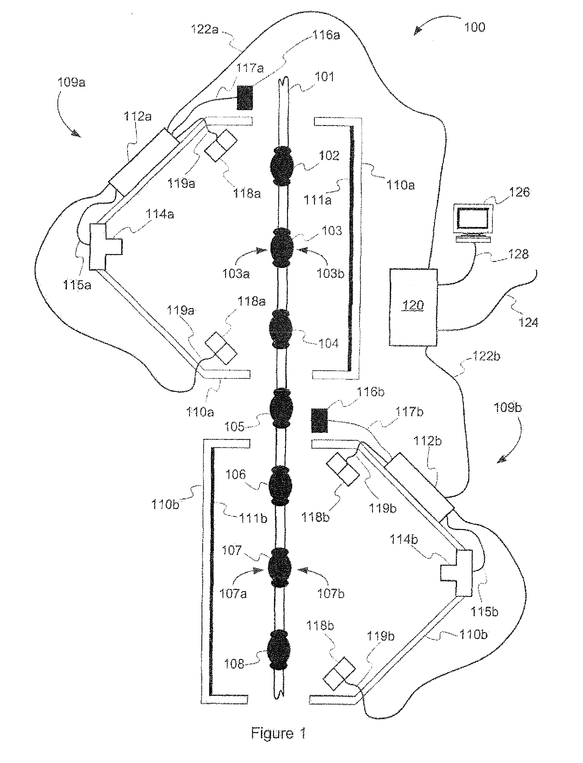
The present invention further relates to a system and method for classifying a meat carcass as described above which activates an output associated with the classification of the carcass effected in step d. Embodiments of the invention will be described by way of example only with reference to the accompanying drawings, in which: A non-restrictive illustrative embodiment of the present invention is concerned with artificial vision method and system for the inspection of slaughtered poultry or other meat and for classifying the slaughtered poultry or other meat into predefined categories according to predefined inspection parameters. Referring to The front inspection station 109 The breakout boards 112 In the illustrative embodiment the breakout board 112 It is to be understood that the various connectors 115 In operation, whenever a carcass, for example carcass 103, enters the front inspection stations 109 A possible inspection algorithm that may be executed by the processor of the digital camera 114 At block 202 the algorithm starts by acquiring the digital image of the carcass, for example a 640 by 480 pixel image 200 of the front portion 103 Then, at block 206, the algorithm detects if a carcass is present or not as the sensor 116 At block 208, the algorithm detects if the carcass 103 is missing a leg. If a missing leg is detected, the algorithm registers the defect and goes to block 216 to activate the output. If both legs are detected, the algorithm proceeds to block 210. At block 210, the algorithm detects if the carcass 103 is missing a wing or if a wing drum is present. If a missing wing or a wing drum is detected, the algorithm registers the defect and goes to block 216 to activate the output. If both wings are detected, the algorithm proceeds to block 212. At block 212, the algorithm detects the presence of a hole in one of the legs of the carcass 103. If a hole is detected, the algorithm registers the defect and goes to block 216 to activate the output. If no holes are detected, the algorithm proceeds to block 214. At block 214, the algorithm detects the presence of one or more skin condition on the skin of the carcass 103. If a skin condition is detected, the algorithm registers the defect and goes to block 216 to activate the output. If no skin condition is detected, the algorithm proceeds to block 216. Finally, at black 216, the algorithm classifies the front portion 103 It is to be understood that although the above described possible inspection algorithm activates the output as soon as a defect is detected, in an alternative embodiment the inspection algorithm may wait until all defects have been detected and activate the output according to a decision making process based on the presence of specific combinations of defects or may even determine a path amongst many paths depending on the detected combinations of defects. An possible image processing algorithm that may be used, at block 204, to process the digital image 200 to create the high contrast image 201 is depicted by the flow diagram shown in The algorithm starts at block 302 by applying an enhancement filter to the digital image 200 using, for example, the “image domain tool” with an RGB gain of 3.6 for the Red and 0 for both the Blue and the Green. This is to accentuate the pixels belonging to the carcass 103 and may vary depending on the type of carcass being inspected. In this specific example the type of carcass being inspected is poultry. At block 304, the filtered image is transformed into a grayscale image and, at block 306, a threshold filter is applied so as to clarify the image. The “blob” tool with a luminosity threshold of 41% may be used for this purpose. Of course, this threshold may be adjusted depending on the type of carcass, lighting conditions, etc. Then, at block 308, an unrelated structure filter may be applied in order to retain a representation of the present carcass and exclude any wing parts from neighboring carcasses which may be in the field of view of the digital camera 114 The detection of a carcass, which is performed at block 206, may be performed by detecting the presence of at least 50,000 pixels in the high contrast image 201 using, for example, the “pixel counter” tool. This allows for the elimination of part of a wing from a neighboring carcass which may have been in the field of view of the digital camera 114 The detection of the presence of one or two legs, which is performed at block 208, may be performed by detecting if there are two or four contrast changes along a line placed across where the legs should be present on the high contrast image 201. Alternatively, the detection of the presence of one or two legs may be performed by detecting if there is at least one contrast change along each of two lines (not shown) placed across where each of the legs should be present on the high contrast image 201. A possible algorithm for the detection of the presence of the wings that may be used at block 210 is depicted by the flow diagram shown in At block 312 the algorithm starts by setting the side of the carcass 103 to be inspected to the right side. Then, at block 314, the farthest point (pixel) 230 from the center of the carcass, e.g. the pixel with the lowest y coordinate value, is identified, as shown in At block 316, the algorithm identifies an upper reference point 240. The algorithm performed to identify the upper reference point 240 will be detailed further below. Using the upper reference point 240 identified at block 316, the algorithm, at block 318, sets detection windows anchor points 242 At block 320, the detection windows 242 and 244 are positioned using anchor points 242 At block 322, the length of the wing is estimated by computing the distance between the farthest point 230 and the upper reference point 240. It is to be understood that any other suitable reference points along the contour 201 At block 328, the width of the wing is estimated by computing the distance 250 between the two farthest points 246, 248 along the contour 201 At block 332, the number of pixels in the wing is estimated by computing the number of pixels within detection window 242. The “pixel counter” tool may be used to determine number of pixels within detection window 242. Then, at block 334 the algorithm verifies if the estimated number of pixels in the wing is greater than 4,845 pixels. If not, the algorithm goes to block 336 were it registers that a wing drum is present instead of a wing and then exits. At block 338, the algorithm verifies if the left side of the high contrast image 201 has been inspected. If not, at block 340, the algorithm sets the side of the carcass 103 to be inspected to the left side and goes back to block 314. If both sides of the carcass 103 have been inspected, the algorithm exits. It is to be understood that the example algorithm described above exits as soon as a defect is detected but that in alternative embodiment the algorithm may wait until all defects have been detected before exiting. A first embodiment of a possible algorithm for the identification of the upper reference point that may be used at block 316 is depicted by the flow diagram shown in At block 502 the algorithm starts by setting an initial point 236. This initial point 236 is selected as being the point having the highest x coordinate amongst the point located on a path 234 along the contour 201 At block 504, the algorithm verifies if the difference in the y axis coordinates (D(y)) of the first eight points along path 234 is less than 10. If so, the algorithm proceeds to block 506 where the coordinates of the reference point of the previous image are returned and then exits. This step is to help eliminate cases where two adjacent carcasses are in contact or very close proximity. The “fine fit” tool may be used to determine the first eight points along path 234. At block 508, the next point in the decreasing x axis direction along path 234 is determined. For example, the next point after initial point 236 is point 237, and after point 237 is point 238. The “line fit” tool may be used to determine the next point along path 234. Then, at block 510, the algorithm verifies if the difference in the y axis coordinates (D(y)) of the last two points is higher than 6 and the difference in the x axis coordinates as a ratio of the total x axis distance of path 234 (Dp(x)) of the last point, i.e. the difference in the x axis coordinates between the last point and point 236 divided by the difference in x axis coordinates between point 236 At block 514, the algorithm verifies if the difference in the y axis coordinates (D(y)) of the last three points is higher than 6 and the difference in the x axis coordinates as a ratio of the total x axis distance of path 234 (Dp(x)) of the last point is greater than 25% (point 236 Finally, at block 518, the algorithm verifies if the difference in the x axis coordinates as a ratio of the total x axis distance of path 234 (Dp(x)) of the last point is equal to 100% (point 236 Basically, the algorithm travels along path 234 until it detects the beginning of the wing, in which case it returns the coordinates of the point just before the start of the wing or the point 236 A second embodiment of a possible algorithm for the identification of the upper reference point that may be used at block 316 is depicted by the flow diagram shown in At block 602 the algorithm starts by setting an initial point 236. This initial point 236 is selected as being the point having the highest x coordinate amongst the point located on a path 234 along the contour 201 At block 604 a counter is set to 1 following which, at block 606, the next point in the decreasing x axis direction along path 234 is determined. For example, the next point after initial point 236 is point 237, and after point 237 is point 238. The “line fit” tool may be used to determine the next point along path 234. Once the next point is determined, at block 608, the counter is increased by 1. Then, at block 610, the algorithm verifies if the difference in the y axis coordinates (D(y)) of the last two points is higher than 6, which would indicate that the algorithm has reached the beginning of the wing. If so, the algorithm proceeds to block 612 where the coordinates of the previous point is returned. However, if the difference in the y axis coordinates (D(y)) of the last two points is not higher than 6, the algorithm proceeds to block 614 where it verifies if the counter has reached 50. If so, the algorithm proceeds to block 616 where the coordinates of the last point is returned. If not, the algorithm goes back to block 606 to find the next point along path 234. Basically, the algorithm travels along path 234 until it detects the beginning of the wing, in which case it returns the coordinates of the point just before the start of the wing or the value of the 50th point along the path if the beginning of the wing has not been detected yet. For example, if the algorithm had just determined point 240 as the next point, it would verify if the difference in the y axis coordinates (D(y)) of point 240 and point 239 is higher than 6. It is higher than 6 then the returned coordinates would be those of point 239. On the other hand, if the difference in y axis coordinates was not higher than 6 then the algorithm would verify if point 240 was the 50th point along path 234, by verifying if the counter had reached 50. If so, the algorithm would return the coordinates of point 240, if not, it would go back to block 606 in order to determine the next point along path 234. A possible algorithm for the detection of the presence of a hole in one of the legs that may be used at block 212 is depicted by the flow diagram shown in At block 352 the algorithm starts by setting the side of the carcass 103 to be inspected to the right side. Then, at block 354, a lower reference point 254 is determined. To determine the coordinates of the lower reference point 254 a line 252 is place over the contour 201 At block 356, using the lower reference point 254 identified at block 354, the algorithm sets a detection window 256 anchor point 256 At block 358, the detection window 256 is positioned using anchor point 256 At block 360, the number of consecutive black pixels within detection window 256, but not touching the sides of the detection window 256, is computed. The “pixel counter” tool may be used to determine number of consecutive black pixels within detection window 242. In order to better detect the presence of holes, the “blob” tool may be used with a threshold of 81% before computing the number of consecutive black pixels. This as for effect to set to black any lighter intensity pixels that may represent damage skin around the holes which may isolate black pixels from one another. Then, at block 364 the algorithm verifies if the computed number of consecutive black pixels is lower is lower than 605 pixels. If not, the algorithm goes to block 366 were it registers that a hole is present in a leg and exits. Finally, at block 370, the algorithm verities if the left side of the high contrast image 201 A possible algorithm for the detection of the presence of a skin condition that may be used at block 214 is depicted by the flow diagram shown in At block 372 the algorithm starts by setting a center detection window 260 anchor point 260 At block 374, the center detection window 260 is positioned using anchor point 260 At block 376, the algorithm computes the number of pixels with a color corresponding to a skin condition within center detection window 260 placed on the digital image 200. The “pixel counter” tool, in conjunction with a table of RGB values corresponding to colors associated with the skin condition, may be used to determine number of pixels with a color corresponding to the skin condition within center detection window 260. Then, at block 378, the algorithm verifies if the number of pixels with a color corresponding to the skin condition is lower than 250 pixels. If not, the algorithm goes to block 380 were it registers that the skin condition is present and exits. At block 382, the algorithm sets the side of the carcass 103 to be inspected to the right side. Then, at block 384, using the upper reference point 240 identified at block 316, the algorithm sets an upper side detection window 258 anchor point 258 At block 386, the upper side detection window 258 is positioned using anchor point 258 At block 388, the algorithm computes the number of pixels with a color corresponding to the skin condition within upper side detection window 258 placed on the digital image 200. The “pixel counter” tool, in conjunction with a table of RGB values corresponding to colors associated with the skin condition, may be used to determine number of pixels with a color corresponding to the skin condition within upper side detection window 258. Then, at block 390, the algorithm verifies if the number of pixels with a color corresponding to the skin condition is lower than 330 pixels. If not, the algorithm goes to block 392 were it registers that the skin condition is present and exits. At block 394, the algorithm sets a lower side detection window 262 anchor point 262 At block 396, the lower side detection window 262 is positioned using anchor point 262 At block 398, the algorithm computes the number of pixels with a color corresponding to the skin condition within center detection window 262 placed on the digital image 200. The “pixel counter” tool, in conjunction with a table of RGB values corresponding to colors associated with the skin condition, may be used to determine number of pixels with a color corresponding to the skin condition within center detection window 262. Then, at block 400, the algorithm verifies if the number of pixels with a color corresponding to the skin condition is lower than 353 pixels. If not, the algorithm goes to block 402 were it registers that the skin condition is present and exits. At block 404, the algorithm verifies if the left side of the high contrast image 201 has been inspected. If not, at block 406, the algorithm sets the side of the carcass 103 to be inspected to the left side and goes back to block 384. If both sides of the carcass 103 have been inspected, the algorithm exits. It is to be understood that various skin conditions may be detected, each skin condition having a table of RGB values corresponding to colors associated with the skin condition. Examples of skin conditions may be the presence of flesh, i.e. areas where the skin is missing, or redness of the skin. RGB values corresponding to colors associated with the presence of flesh may be predetermined by taking digit are images of flesh and registering the ranges of RGB values within a table. Table 1 gives an example of RGB values that may be used for poultry breast flesh colors It is to be understood that the range of flesh color RGB values may vary with the type carcass, lighting conditions, body part, etc. RGB values corresponding to colors associated redness of the skin may be predetermined by taking digital images of redness and registering the ranges of RGB values within a table. Table 2 gives an example of RGB values that may be used for poultry breast redness colors. It is to be understood that the range of redness color RGB values may vary with the type carcass, lighting conditions, body part, etc. It is to be understood that the various values for the pixel thresholds and windows dimensions are based on the size of the digital image, which is 640 by 480 pixels in the example embodiment, the type of carcass being inspected and the specific inspection criteria. The specified values are meant as examples only and other values may be used depending on the application and quality levels. Although the present invention has been described by way of a particular embodiment and examples thereof, it should be noted that it will be apparent to persons skilled in the an that modifications may be applied to the present particular embodiment without departing from the scope of the present invention. An artificial vision inspection method and system which takes photographs, on either sides, of poultry or other meat at various stages of processing as they pass by on hanging racks. The method and system then sorts the meat according to quality parameters selected by the user, from presence or absence of parts to size to coloration. 1. A method for classifying a meat carcass, comprising the steps of:
a. acquiring at least one digital image of the carcass; b. processing the digital image; c. verifying the processed digital image in order to detect the presence of at least one defect; d. classifying the carcass in response to the presence or not of the at least one defect. 2. A method for classifying a meat carcass according to e. activating an output associated with the classification of the carcass effected in step d. 3. A method for classifying a meat carcass according to 4. A method for classifying a meat carcass according to i. applying an enhancement filter to the digital image; ii. transforming the enhancement digital image to grayscale; iii. applying a threshold filter to the grayscale image; iv. applying an unrelated structure filter. 5. A method for classifying a meat carcass according to 6. A method for classifying a meat carcass according to 7. A method for classifying a meat carcass according to 8. A method for classifying a meat carcass according to 9. A method for classifying a meat carcass according to 10. A method for classifying a meat carcass according to 11. A method for classifying a meat carcass according to 12. A method for classifying a meat carcass according to 13. A method for classifying a meat carcass according to 14. A method for classifying a meat carcass according to 15. A method for classifying a meat carcass according to i. estimating the length in pixels of the wing; ii. verifying that the length of the wing is over a first threshold; iii. estimating the width in pixels of the wing; iv. verifying that the width of the wing is over a second threshold; v. estimating the number of pixels of the wing; vi. verifying that the number of pixels of the wing is over a third threshold. 16. A method for classifying a meat carcass according to 17. A method for classifying a meat carcass according to i. estimating the number of consecutive black colored pixels within a detection window; ii. vi. verifying that the number of consecutive black colored pixels is below a fourth threshold. 18. A method for classifying a meat carcass according to 19. A method for classifying a meat carcass according to i. estimating the number of pixels having RGB values to colors associated with a skin condition within at least one detection window; ii. vi. verifying that the number of pixels having RGB values to colors associated with a skin condition is below a fifth threshold. 20. A method for classifying a meat carcass according to CROSS-REFERENCE TO RELATED APPLICATION
TECHNICAL FIELD
BACKGROUND
SUMMARY
BRIEF DESCRIPTION OF THE FIGURES
DETAILED DESCRIPTION
Image Processing
Carcass Detection
Leg Detection
Wing Detection
Identification of the Upper Reference Point
Hole Detection
Skin Condition Detection
Presence of Flesh
RGB values for poultry breast flesh colors Color number Red component Green component Blue component 1 28.2 to 34.1 7.8 to 10.6 6.3 to 10.6 2 25.1 to 34.1 6.3 to 9.0 6.3 to 9.0 3 28.2 to 37.3 6.3 to 9.0 6.3 to 12.2 4 28.2 to 31.0 9.4 to 12.2 0.0 to 5.9 5 28.2 to 34.1 9.4 to 12.2 0.0 to 5.9 6 31.4 to 34.1 12.5 to 13.7 6.3 to 9.0 7 31.4 to 34.1 9.4 to 12.2 6.3 to 9.0 8 25.1 to 27.8 7.8 to 9.0 0.0 to 5.9 9 25.1 to 27.8 6.3 to 7.5 0.0 to 5.9 10 31.4 to 34.1 0.0 to 9.0 3.1 to 9.0 11 31.4 to 37.3 11.0 to 12.2 3.1 to 9.0 12 37.6 to 43.5 9.4 to 12.2 0.0 to 5.9 13 40.8 to 43.5 14.1 to 18.4 3.1 to 9.0 14 34.5 to 43.5 3.1 to 7.5 0.0 to 9.0 15 43.9 to 49.8 12.5 to 16.9 3.1 to 12.2 16 40.8 to 46.7 9.4 to 12.2 0.0 to 9.0 17 15.7 to 21.6 6.3 to 10.6 0.0 to 9.0 Redness of the Skin
RGB values for poultry breast redness colors Color number Red component Green component Blue component 1 31.4 to 37.3 11.0 to 12.2 3.1 to 9.0 2 37.6 to 43.5 9.4 to 12.2 0.0 to 5.9 3 40.8 to 43.5 14.1 to 18.4 3.1 to 9.0 4 34.5 to 43.5 3.1 to 7.5 0.0 to 9.0 5 43.9 to 49.8 12.5 to 16.9 3.1 to 12.2 6 40.8 to 46.7 9.4 to 12.2 0.0 to 9.0 7 15.7 to 21.6 6.3 to 10.6 0.0 to 9.0