Redundant Hoist Rope System
This invention pertains to gantry cranes and, more particularly, to hoisting systems employed with gantry cranes. Cranes and hoisting systems are used in a number of industries to lift heavy objects and reposition them someplace else. Gantry cranes, for example, are used in ship and rail yards to load and off-load containers. A typical crane utilizes one or more wire ropes to raise and transfer a load from one place to another. In many instances, these wire ropes are used in conjunction with a stabilizing or lifting beam. While in transit, the weight of the load is distributed amongst all of the wire ropes that are used to raise and support its repositioning. Typically, more than one rope is used as the distribution of the weight amongst multiple ropes allows for greater lift capacity and also provides some measure of safety should one of the ropes fail. While the use of multiple ropes provides a measure of safety, the potential for catastrophic failure still exists should there be a complete failure of one of the ropes. Therefore, it is desirable to have a system that would provide an added safeguard that would completely support the weight of a given load in the event of a complete failure of one of the hoisting ropes. An apparatus capable of supporting a portion of the weight of a load being transferred by a lifting device in the event of a complete failure of one of the hoisting ropes is disclosed. The apparatus includes a support structure attached atop a beam of the lifting device, and a support bar pivotally attached to the support structure. The support structure includes a stop portion that is in contact with the beam and has an upper surface opposed to an undersurface of the support bar. Also disclosed is an hoist system capable of preventing an uncontrolled dropping of a load from a lifting device. The hoist system is comprised of a beam and a stabilizing beam parallel to the beam. A hoist drum is located atop the beam and a first support bar straddles the beam and is pivotally attached to a support structure proximal to a first end of the beam. A second support bar straddles the beam and is pivotally attached to a support structure proximal to a second end of the beam. A first pair of wire ropes, each one of which is capable of supporting the entire load on one end of the stabilizing beam is wrapped around the hoist drum and has a first end attached to the hoist drum while a second end is reeved through a respective sheave, located proximal to a first end of the stabilizing beam, and is attached to the support bar. A second pair of wire ropes each one of which is capable of supporting the entire load on one end of the stabilizing beam are wrapped around the hoist drum and have a first end attached to the hoist drum and a second end reeved through a respective sheave located proximal to a second end of the stabilizing beam and attached to the second support bar. The following examples further illustrate the invention but, of course, should not be construed as in any way limiting its scope. The invention involves an apparatus 10 for preventing an uncontrolled dropping of a load 12 from a lifting device 14. An embodiment related to a gantry crane is shown in In an embodiment, the apparatus 10, as shown in In an embodiment, the support bar 20 is made of a steel, however, other suitable materials may be used without departing from the scope and spirit of the invention. As shown in Also disclosed is a hoist system 52 capable of preventing an uncontrolled dropping of a load 12 from a lifting device 14. The hoist system 52, as shown in In an embodiment shown in Although the wire ropes in the hoist system are reeved through at least one sheave 42 In an embodiment, each of the support bars 20 includes a first end 28 and a second end 30 that extend outwardly from the respective sides of the beam 18. In a particular embodiment, the first end 28 and the second end 30 may extend outwardly and down from the respective sides of the beam 18. An underside 26 of each support bar 20 is displaced from an upper surface 24 of their respective support structures 16. In another embodiment, as shown in When in operation, a load 12 is attached to the hoist system 52 on a lifting device 14 such as the gantry crane shown in Should one of the wire ropes 34 In another embodiment, as shown in All references, including publications, patent applications, and patents, cited herein are hereby incorporated by reference to the same extent as if each reference were individually and specifically indicated to be incorporated by reference and were set forth in its entirety herein. The use of the terms “a” and “an” and “the” and similar referents in the context of describing the claimed apparatus, device, system or method (especially in the context of the following claims) are to be construed to cover both the singular and the plural, unless otherwise indicated herein or clearly contradicted by context. Recitation of ranges of values herein are merely intended to serve as a shorthand method of referring individually to each separate value falling within the range, unless otherwise indicated herein, and each separate value is incorporated into the specification as if it were individually recited herein. All methods described herein can be performed in any suitable order unless otherwise indicated herein or otherwise clearly contradicted by context. The use of any and all examples, or exemplary language (e.g., “such as”) provided herein, is intended merely to better illuminate the claimed apparatus, device, system or method and does not pose a limitation on the scope of the claimed apparatus, device, system or method unless otherwise claimed. No language in the specification should be construed as indicating any non-claimed element as essential to the practice of the claimed apparatus, device, system or method. Preferred embodiments of the claimed apparatus, device, system or method are described herein, including the best mode known to the inventors for carrying out the claimed apparatus, device, system or method. It should be understood that the illustrated embodiments are exemplary only, and should not be taken as limiting the scope of the claimed apparatus, device, system or method. An apparatus capable of supporting a portion of the weight of a load being transferred by a lifting device in the event of a complete failure of one of the hoisting ropes is disclosed. The apparatus includes a support structure attached atop a beam of the lifting device, and a support bar pivotally attached to the support structure. The support structure includes a stop portion that is in contact with the beam and has an upper surface opposed to an undersurface of the support bar. A hoist system is also disclosed. 1. A safety apparatus for preventing an uncontrolled dropping of a load from a lifting device, the safety device comprised of:
a support structure attached to a beam of the lifting device; and a support bar pivotally attached to the support structure, said support bar straddling the beam and having an undersurface displaced from an upper surface of the support structure; a first and a second end of the support bar extending outwardly from respective sides of the beam, wherein each of the first and second ends of the support bar are capable of receiving an end portion of a first and second wire rope, respectively. 2. The safety apparatus of the support structure includes a stop portion having a first width and a first length; and the undersurface of the support bar includes a stop-portion contacting section that is approximately as wide and as long as the first width and first length of the stop portion. 3. The safety apparatus of a stop contacting portion having a first width and a first length is located above the support bar; and the upper surface of the support bar includes a stop-portion contacting section that is approximately as wide and as long as the first width and first length of the stop portion. 4. The safety apparatus of 5. The safety apparatus of the support structure is attached atop a beam of the lifting device each of the first and second wire ropes are reeved through a first and second sheave, respectively; and each sheave is located on a respective first and second end of a stabilizing beam. 6. The safety apparatus of a first and second threaded connector attaches the respective end portion of each of the first and second wire ropes to the respective first and second ends of the support bar. 7. The safety apparatus of 8. A hoist system capable of preventing an uncontrolled dropping of a load from a lifting device, the hoisting system comprised of:
a beam and a stabilizing beam parallel to the beam; a hoist drum located on the beam; a first support bar straddling the beam and pivotally attached to a support structure proximal to a first end of the beam; a second support bar straddling the beam and pivotally attached to a support structure proximal to a second end of the beam; a first pair of wire ropes wrapped around the hoist drum, each rope in the pair of wire ropes having a first end attached to the hoist drum, a second end reeved through a respective sheave located proximal to a first end of the stabilizing beam and attached to the first support bar; and a second pair of wire ropes, each rope in the second pair of wire ropes being wrapped around the hoist drum and having a first end attached to the hoist drum, a second end reeved through a respective sheave located proximal to a second end of the stabilizing beam, and attached to the second support bar. 9. The hoist system of 10. The hoist system of each of the dead end support bars includes a first end and a second end that extend outwardly from the respective sides of the beam, and an underside that is displaced from an upper surface of their respective support structures. 11. The hoist system of the support structure has a first width; and the undersurface of the support bar includes a support structure contacting portion that is as wide as the first width of the support structure. 12. The hoist system of 13. The hoist system of one of the first and second ends of the support bar is raised when a load is removed from the rope attached to the respective one of said ends, the other of the first and second ends is lowered; the underside of the support bar proximal to the other of the first and second end contacts the upper surface of the support structure; and the wire rope attached to the lowered end of the support bar is capable of individually supporting the entire portion of the load that is reflected to the lowered end of the support bar. 14. The hoist system of a stop contacting portion having a first width and a first length is located above the support bar; the upper surface of the support bar includes a stop-portion contacting section that is approximately as wide and as long as the first width and first length of the stop portion. one of the first and second ends of the support bar is raised when a load is removed from the rope attached to the respective one of said ends, the other of the first and second ends is lowered; the upper surface of the support bar proximal to said raised end contacts the stop contacting portion located above the support bar; and the wire rope attached to the lowered end of the support bar is capable of individually supporting the entire portion of the load that is reflected to the lowered end of the support bar. 15. The hoist system of the first pair of wire ropes are wrapped around a first hoist drum; and the second pair of wire ropes are wrapped around a second hoist drum. 16. The hoist system of FIELD OF THE INVENTION
BACKGROUND OF THE INVENTION
BRIEF SUMMARY OF THE INVENTION
BRIEF DESCRIPTION OF THE DRAWINGS
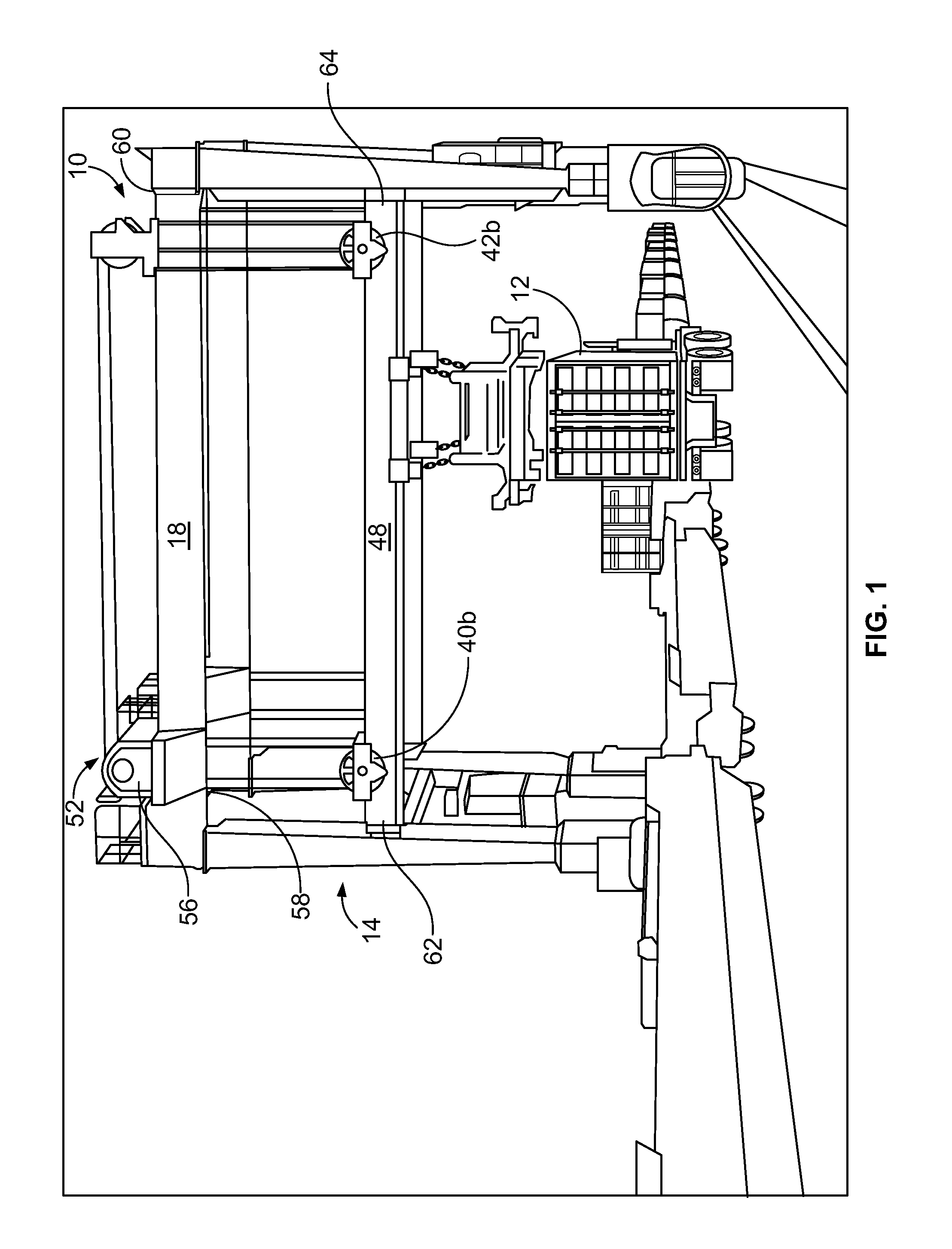
DETAILED DESCRIPTION OF THE INVENTION