LED-BASED LUMINAIRE
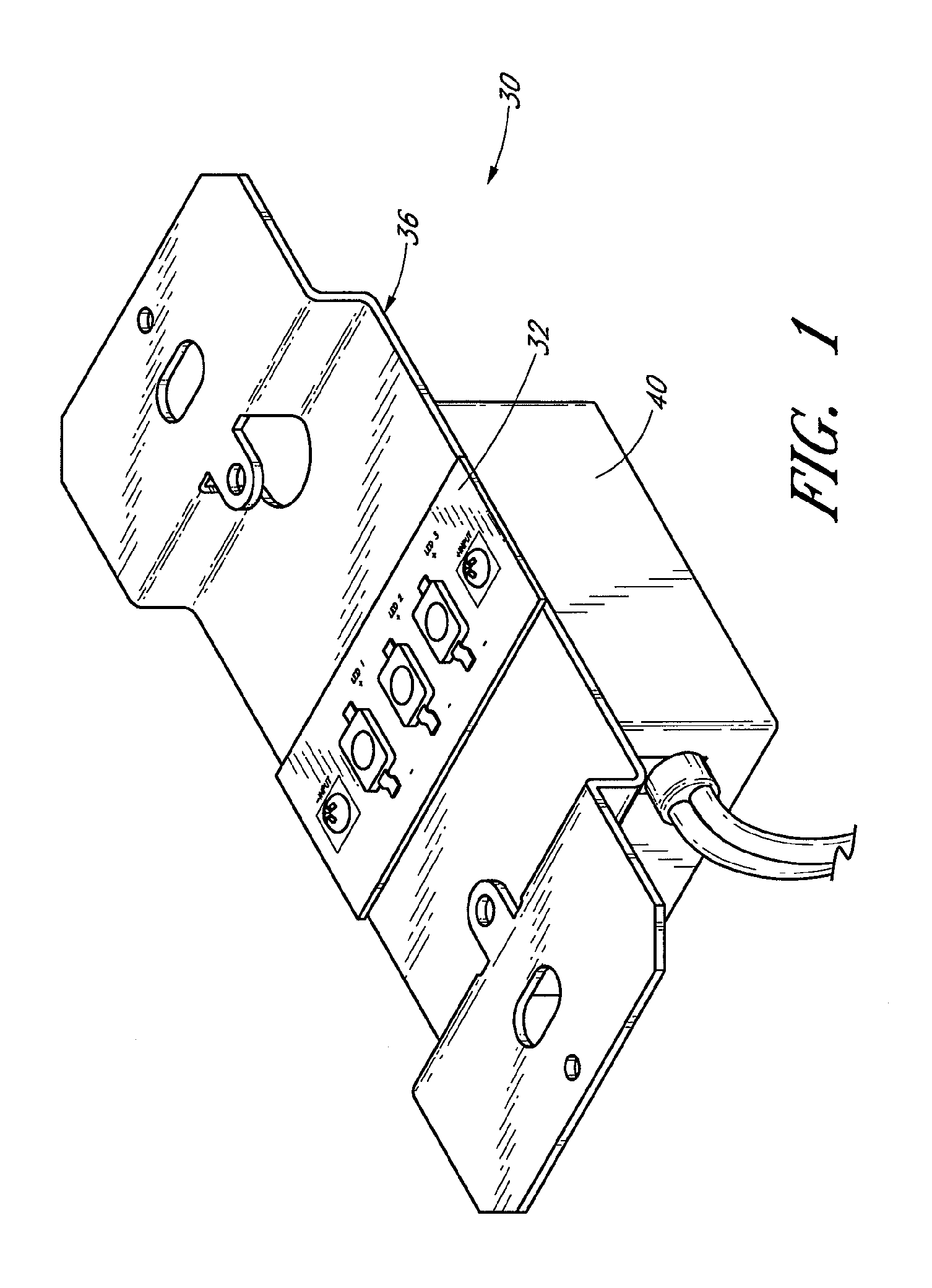
This application is a continuation of U.S. Ser. No. 11/434,663, which was filed May 15, 2006, and which is based upon and claims the benefit of U.S. application Ser. No. 60/681,072, which was filed on May 13, 2005. The entirety each priority application is hereby incorporated by reference. 1. Field of the Invention The present invention relates generally to light emitting diode (LEDs) based lighting devices, and more particularly to configurations for LED-based luminaires and for managing heat generated by LEDs in such luminaires. 2. Description of the Related Art Conventional lighting applications typically employ incandescent or gas-filled bulbs. Incandescent bulbs typically do not have long operating lifetimes and thus require frequent replacement. Such bulbs also have substantially high power requirements. Gas-filled tubes, such as fluorescent or neon tubes, may have longer lifetimes, but operate using dangerously high voltages, and may contain toxic materials such as mercury. In contrast, light emitting diodes (LEDs) are relatively inexpensive, operate at low voltage, and have long operating lifetimes. Additionally, LEDs consume relatively little power and are compact. These attributes make LEDs particularly desirable and well-suited for many lighting applications. Lighting designers wishing to use LEDs often create LED-based luminaires that employ a plurality of LEDs in a “light bulb” type of arrangement such as that used with typical incandescent and some fluorescent lamps. By configuring LEDs to fit an arrangement specifically suited to old incandescent technology, such designs typically use such LEDs in a manner that compromises effectiveness and is unduly expensive. Accordingly, there is a need in the art for LED-based lighting fixtures that are configured to maximize the lighting effectiveness of the LEDs, appropriately manage heat generated by the LEDs, and reduce the costs associated with such fixtures. There is also a need in the art for a simplified and standardized LED luminaire. There is a further need for an LED-based luminaire system including various componentry that can be mixed and matched as appropriate to custom-design luminaires for lighting applications using only standard components. In accordance with one embodiment, the present invention provides a lighting apparatus comprising a lighting module, a mount member, and a power driver. The module has at least one light emitting diode (LED), a dielectric member, and a plurality of electrically conductive contacts disposed on the dielectric member. The contacts are configured to mount the at least one LED to supply electrical current to the LED. The mount member has a module receiving portion adapted to engage the lighting module. The power driver is arranged on a side of the mount member generally opposite the lighting module, and is adapted to receive power and condition the power to a desired state. At least one fastener is configured to engage the lighting module and the driver so as to secure the lighting module and driver onto the mount member. The fastener is electrically conductive, and conducts electric power from the driver to a contact of the LED module. In another embodiment, the driver comprises connectors adapted to electrically and physically engage a pair of fasteners. The connectors are polarized and are substantially enclosed within a driver housing. In yet another embodiment, the mount member has a pair of mounting apertures adapted to accommodate the fasteners, and the fasteners physically and electrically engage positive and negative input contacts, respectively, of the lighting module. In another embodiment, the present invention provides a lighting apparatus comprising alighting module and a mount member. The lighting module has at least one light emitting diode (LED), a dielectric member and a plurality of electrically conductive contacts disposed on the dielectric member. A positive input contact and a negative input contact are adapted to receive positive and negative electric power supplied thereto. The at least one LED is mounted to the electrically conductive contacts so that electric power flows between the positive and negative input contacts and across the LED. The mount member has a module receiving portion adapted to engage the lighting module. The mount member comprises a metal that is coated with a material that increases the surface area of the mount member relative to uncoated metal, and the coating material provides a visually bumpy-textured surface. In another embodiment, the mount member is powder coated. In a still further embodiment, the powder coat is generally white. In accordance with yet another embodiment, the present invention provides a lighting fixture comprising a mounting base, a lighting module and a power driver. The lighting module comprises at least one light emitting diode (LED), a positive contact, a negative contact, and a mount body, the at least one LED adapted to be powered by electric power flowing between the positive and negative contacts. The power driver is adapted to accept an input electric power and condition the input power to create a desired output electric power, and the driver comprises a pair of polarized connectors energized with the output electric power. A plurality of fasteners are adapted to electrically connect the positive and negative contacts to the polarized connectors. A light modifying apparatus is arranged adjacent the lighting module. A fixture housing at least partially encloses the lighting module, light modifying apparatus, and at least a portion of the base. The lighting module and driver are disposed on opposing sides of the mounting base, and the fasteners are adapted to physically connect the lighting module, driver, and mounting base. In a yet further embodiment, a luminaire is adapted to be customized to a plurality of configurations. The luminaire comprises a lighting module, a mount member, and a power driver. The lighting module comprises a body, a plurality of electrically-conductive circuit traces, a positive and negative input trace each being configured to accept a positive and negative electrical input, respectively, and at least one light emitting diode (LED) attached to the traces so that electric power from the positive and negative input traces will flow through the LED. The mount member comprises a lighting module mounting portion and a fixture mount portion. The module mounting portion has a first pair of spaced apart mounting apertures and a second pair of spaced apart mounting apertures, each pair of mounting apertures being spaced a distance generally corresponding to a distance between the positive and negative input traces of the lighting module. The power driver is adapted to supply an output power to a pair of polarized output connectors. A pair of electrically-conductive fasteners are adapted to connect to the lighting module and power driver connectors so as to supply electric power from the polarized connectors to the positive and negative input traces of the lighting module. The driver and lighting module are attached to opposing sides of the mount member, and the fasteners extend through one of the first or second pairs of spaced apart mounting apertures of the mount member. In a still further embodiment, the driver has a first footprint shape upon the mount member when the fasteners are disposed through the first pair of mounting apertures, and a second footprint shape upon the mount member when the fasteners are disposed through the second pair of mounting apertures, and the first and second footprint shapes are substantially the same. In still another embodiment, the lighting module comprises a plurality of LEDs, and a light pattern emitted by the lighting fixture when the module is fastened into place via the first pair of mount apertures is substantially different than a light pattern emitted by the lighting fixture when the module is fastened into place via the second pair of mount apertures. In accordance with still a further embodiment, the present invention provides a channel illumination device. A metal casing of the device has a plurality of walls and a back. A plurality of lighting modules are arranged on the casing. Each lighting module comprises a body, a plurality of electrically-conductive circuit traces, a positive and negative input trace each being configured to accept a positive and negative electrical input, respectively, and at least one light emitting diode (LED) attached to the traces so that electric power from the positive and negative input traces will flow through the LED. The plurality of lighting modules are attached to at least one of the casing walls and back so that heat generated by the LEDs will flow through the module body and to the casing. A surface of the metal casing comprises a coating having a visibly bumpy surface texture so that the coated mount member surface has a greater average feature height than a surface that appears substantially flat. Further embodiments can include additional inventive aspects, and apply additional inventive principles that are discussed below in connection with preferred embodiments. With reference first to In the illustrated embodiment, a pair of threaded fasteners 42 secure the lighting module 32 onto the mount member 36 and the driver 40. The fasteners 42 preferably extend through apertures 44, 46 formed through the lighting module 32 and mount member 36, and engage threaded mount bosses 50 in the driver 40. Non-conductive inserts 52 electrically insulate the mount member 36 and portions of the module 32 from the fasteners 42. Preferably, the mount bosses 50 in the driver 40 are polarized, which is to say a voltage drop is provided across the mount bosses 50. Further, preferably the fasteners 42 are configured to conduct electricity in addition to securing the lighting module 32 into place. As such, preferably electric power is communicated across the lighting module 32 via the fasteners 42, which contact the mount bosses 50 of the power driver 40. With additional reference to In the embodiment illustrated in The rectangular geometry of the illustrated embodiment is especially suitable for the illustrated luminaire embodiment 30 discussed herein. It is to be understood, however, that other embodiments may benefit from differing module configurations. For example, it is contemplated that modules may be square, circular, oval, irregularly-shaped or may have widely varying rectangular dimensions (such as being especially long and thin). Additionally, although the illustrated modules are relatively flat, it is understood that other embodiments may include modules having simple or complex three dimensional shapes. With continued reference to Further, the LEDs 34 may be all the same color, may be of different colors, or may include combinations of LED colors that are specifically tailored to create a particular color effect. For most space lighting applications the LEDs preferably emit white light. With reference also to The mounting field 70 preferably is substantially flat so as to complement the flat body 54 of an associated lighting module 32. In other embodiments, the lighting module may have an irregular or curving surface that preferably is configured to complement the lighting module body surface. As such, heat is readily transferred from the lighting module body 54 to the mount member 36. Preferably, the mount member is made of a material having relatively high heat conductance properties, such as metal. In the illustrated embodiment, the mount member 36 is constructed of a single piece of aluminum. One or more fixture mount apertures 72 preferably is disposed in each of the fixture mount portions 68 of the mount member. One or more of these fixture mount apertures 72 preferably is employed to secure the mount member 36 to its designated location. More specifically, for example, the fixture mount apertures 72 may align with bolt or screw holes in an electrical junction box or the like so as to enable mounting of the mount member 36 in an electrical junction box. In additional embodiments, one or more of the fixture mount apertures 72 corresponds with mounting bolts of another type of lighting fixture. It is to be understood that, in other embodiments, the mount member may have other shapes and configurations so as to fit as desired relative to a lighting fixture so as to provide the light source for the lighting fixture. In the embodiment illustrated in In the illustrated embodiment, heat from the LEDs on the lighting module 32 is communicated to the heat conductive module body 54, which in turn communicates the heat to the mount member 36. The mount member acts as a heat sink, absorbing the heat from the lighting module and thus communicating heat away from the LEDs 34. Since LEDs tend to deteriorate very quickly if subjected to excessive heat, the mount member's operation as a heat sink can provide a valuable role in ensuring longevity of an associated LED luminaire. The mount member 36, which functions as a heat sink, preferably accumulates heat and disperses such heat to the environment. In the illustrated embodiment, the mount member 36 is formed of aluminum and is powder coated. Most preferably the powder coat is a glossy white color and has a rough or bumpy surface texture. In a preferred embodiment, the overall surface area of the mount member is increased significantly by the bumpy powder coat relative to flat metal. In one embodiment, the overall surface area due to the rough-textured powder coat is increased by up to about three times relative to a smooth flat metal surface. In another embodiment, the surface area is at least about doubled. Coating the mount member 36 with a bumpy-textured coating may not always vary the surface area extensively. However, changing the surface texture of the raw metal increases its heat transfer properties. For example, in some embodiments the mount member may be a polished or unpolished aluminum. Application of a covering such as a visibly bumpy-surface powder coat changes the surface texture of the device. Applicants have learned that adding a rough surfaced, bumpy powder coat to a raw or polished aluminum mount member improves the heat conductivity properties of the mount member. Specifically, Applicant has measured temperature decreases between about 30-50% when a bumpy white powder coated mount member heat sink is used in place of a raw metal mount member heat sink. Applicant has also noted improved heat conductance properties and decreased measured temperatures relative to raw metal even when the mount member is powder coated with a relative smooth powder coat. Most preferably, the mount member is coated with a light-and heat-reflective color, such as gloss or semi-gloss white; however, other colors may be used. With continued reference to In the illustrated embodiment, the bumpy powder coating does not simply increase the surface area of the mount member relative to raw metal. Rather, the bumpy powder coating increases the average feature height of the surface of the mount member. Most preferably, the coating is configured to increase the average feature height so as to increase incident air access to and interaction with the peaks and valleys that make up the bumpy surface. Such increased incident air interaction increases the ability of the environmental air to extract heat from the mount member. It is noted that some raw metals, such as aluminum, may appear generally flat to the human eye, but in fact include several peaks and valleys having a relatively low average feature height. A bumpy powder coat may not necessarily increase the surface area of such a raw metal substantially. However, the bumpy powder coat preferably increases the average feature height significantly, and thus increases the ability of the mount member to transfer heat to the environment, relative to a mount member having an uncoated metal surface. The increased average feature height increases the efficiency of heat transfer relative to unfinished aluminum. In certain embodiments, the LEDs 34 of the lighting module 32 emit white light. In current white LED technology, especially “warm” white LEDs, which resemble incandescent white light in color, the LED package includes red phosphors. As such, a spectral distribution curve of the warm white light emitted by such LEDs shows a significant amount of infrared light in the spectrum. Such infrared light readily communicates energy to whatever material it impinges upon, which energy typically is converted to heat within the material. If a mount member were untreated, or were colored black as are conventional heat sinks, such infrared light energy would increase the temperature of the heat sink, thus diminishing its effectiveness as a heat sink. A light-reflective color such as gloss or semi-gloss white, reflects infrared light rays as well as other colors of light, and thus minimizes the accumulation of infrared light energy by the heat sink. Thus, light energy from the infrared light is not transferred to the heat sink, but rather is directed to the environment. As such, the effectiveness of the heat sink in extracting heat from the LEDs is enhanced, as less energy is being absorbed by the heat sink. As such, preferably the light-reflective coating is applied even in areas of the device that are not visible to the outside or to a user looking at the device. Typically heat sinks are painted black in order to better absorb heat. However, as discussed above, in contrast to conventional practice, the mount member, which functions as a heat sink, preferably is painted a light-reflective color. In this lighting-based application, the light-reflective heat sink has increased capacity relative to a conventional black or otherwise low-reflectivity heat sink. In one embodiment, a visibly bumpy-surfaced semi-gloss white powder coat is employed. One suitable powder coat is a polyester TGIC powder coating (TC13-WH09), which is available from Cardinal Industrial Finishes. With additional reference to As shown specifically in With continued reference to As illustrated, preferably all electronic componentry, including the mounting bosses 50, is generally enclosed within the housing 80. The housing includes an outer case 90 and a front plate 92 that complementarily engage one another. Apertures 94 are formed through the plate 92 so as to correspond with the mounting bosses 50. Preferably, the plate apertures 94 are somewhat larger in diameter than the threaded engagement portion 96 of the mount bosses 50. Preferably positive and negative legends are embossed on the plate 92. With particular reference again to With continued reference to With reference next to A power conditioner or driver 140 is configured to be placed on a side of the mount base 136 opposite the lighting modules 32. In the illustrated embodiment, the power driver 140 receives electrical input power from a power source through electrical wires 148. The driver 140 also comprises three pairs of mounting bosses 50A-C. Each pair of mounting bosses 50A-C is configured to power a corresponding lighting module 32A-C. Preferably, threaded fasteners 42 are configured to fit through the lighting module apertures 44, mounting base apertures 146, through an insert 52, and into secure contact with corresponding mount bosses 50A-C of the power driver 140 in a manner as discussed above. Thus, the fasteners 42 secure the lighting modules 32A-C and power driver 140 to the mounting base 136, and the fasteners 42 also deliver electrical power from the driver bosses 50A-C to corresponding modules 32A-C. The mounting base 136 is preferably formed from a material having advantageous heat conductance properties, such as aluminum. As such, the mounting base may operate as a heat sink, absorbing heat generated by the LEDs 34 and dispersing that heat to the environment. In the illustrated embodiment, the base 136 is constructed as a single piece of aluminum. In other embodiments, multi-piece bases may be employed. As discussed above, the portion 152 of the mounting base 136 surrounding the module mounting portion 142 is raised in the illustrated embodiment. Preferably fins 154 are provided in the raised portion 152 of the mounting base 136. Such fins 154 help speed heat transfer from the mounting base to the environment. In the illustrated embodiment, fins are illustrated on the front side of the mounting base 136. It is to be understood that certain fin structures may also be formed in a back side of the mounting base. In the illustrated embodiment the mounting base 136 preferably is powder coated with a bumpy-textured powder coat that creates many peaks and valleys whose feature heights are significant enough or on average to enhance heat transfer relative to an unfinished metal base or flat-coated base. The back housing 138 illustrated in the embodiment shown in With continued reference to Above the lens portion 160 is a protective plate 164 or lens. The protective plate preferably is transparent or translucent, and communicates light from the LEDs 34 therethrough while simultaneously protecting components from access from outside the fixture. A housing face, or cover 134, preferably is configured to lockingly engage to the base 136 and encloses the protective plate 164, lens portion 160, lighting modules 32 and a portion of the base 136. Preferably, the face 134 also comprises a heat conductive material, such as aluminum, that preferably is powder coated. Since the face likely is the most visible portion of the LED luminaire 130, it is anticipated that in certain embodiments a bumpy-surfaced powder coating will be visually undesirable. Nevertheless, even though a raw metal look is acceptable, it is most preferable that the face 134 at least have a smooth powder coat or layer of paint. In any case, it is anticipated that, in some embodiments, internal components such as the base 136 may be rough-texture powder coated, while external portions such as the face 134 may be uncoated or have a different type of surface coating/texture. Preferably, the face 134 includes an internal spacer 170 that generally corresponds to the protective plate 164 and lens 160 so as to the control the position of the protective plate and the lens member relative to the position of the LEDs 34. The spacer 170 preferably depends inwardly from the front portion of the face/cover 134. The face is mounted on the base plate 136 so that the spacer 170 contacts the front 143 of the mounting base. Preferably, the spacer 170 and the fins 154 are sized so that at least a portion of the fins 154 are exposed, allowing heat within the area between the LED modules and the housing face plate to vent through the fins. In the illustrated embodiment, a pair of threaded holes 172 are provided on either side of the cover 134. Additionally, a pair of opposing seats 174 are defined on the mounting base. Preferably, headless bolts, such as grub screws, are threaded into the cover holes 172 so as to engage the corresponding seat 174 formed in the mounting base 136. When both grub screws are in place, the cover is held securely onto the base plate, and the light modifying device 160 and protective lens 164 are enclosed between the cover and the base plate. The fixture 130 preferably can be mounted in several different ways. For example, in the illustrated embodiment, the mounting base 136 preferably includes a pair of slide mount fixture apertures 180. Each slide mount aperture preferably has a first portion 182 with a relatively large diameter, which portion is configured to accept a mount bolt head. An elongate, second portion 184 of the slide mount aperture 180 has a smaller width, and is sized to accommodate a shaft portion of the mount bolt without allowing the bolt head to fit therethrough. Thus, in a conventional manner, a mount bolt head is advanced through the first portion 182 and then the mounting base 136 is rotated so that the mount bolt shaft seats in the second portion 184, thus holding the mount base in place on the mount bolt. Preferably, other apertures 186 are also formed through the mounting base 136 in order to accommodate bolts and/or screws advanced directly through the mounting base. Still further, at least some of such apertures 186 include a plurality of threaded holes adapted to accommodate threaded bolts in order to mount the base 136 in place. In the illustrated embodiment, each of these mounting options are included in the mounting base, thus providing several options for mounting. It is to be understood that still further mounting options can be employed as well. For example, the illustrated embodiment includes another pair of threaded holes 188 along the edges of the mounting base. If desired, a gimble gimbal mechanism can be attached to the mounting base at the threaded edge mount holes 188, and the gimble gimbal mechanism can be used to mount the fixture. With continued reference to With reference next to With reference next to With continued reference to The illustrated circuit 200 not only steps down and rectifies voltage, but provides that voltage evenly across the pairs of mounting bosses 150A-C. When three LED modules 32A-C are attached to the bosses 150A-C as illustrated above in In the illustrated embodiment three identical lighting modules 32A-C are employed. It is to be understood that, in other embodiments, various geometrical configurations can be employed. As such, three or more, or less, lighting modules 32 can be employed in other embodiments, and the lighting modules need not necessarily be the same size and/or shape and may not necessarily employ the same number or color of LEDs. For example, in certain lighting fixtures having other geometric configurations, it may make sense to have smaller lighting modules and larger lighting modules that are powered by the same driver. Preferably, the lighting modules can be connected to a driver without requiring additional wiring between the modules. Principles and aspects discussed in the above embodiments disclose a simple manner of connecting individual modules in place wherein the connection provides both the electric supply and physical connection. Further, one or more modules of a multimodule luminaire may be removed and replaced independent of the other modules. It is to be understood that, in other embodiments, additional physical connectors that are not electrically conductive may also be employed with certain lighting modules. Also, principles and aspects discussed herein may be employed in embodiments in which physical connection and electrical connection are not simultaneously supplied through fasteners. The illustrated circuit diagram anticipates a 120VAC input. However, it is to be understood that the principles disclosed herein can be employed in connection with other input voltage, such as 240vac or high- and low-voltage AC inputs. Of course, changes and enhancements can be made, and additional features can be added to the circuit diagram 200 disclosed in With continued reference to In the illustrated embodiment, three spacer members 210 connect the power conditioning board 192 to the mount board 194. However, only a positive spacer/connector 210+ and a negative spacer/connector 210− conduct electricity to the mount board 194. Preferably, the positive spacer/connector 210+ attaches to the mount board 194 so that positive electrical energy is applied to a positive trace 256 on the second side 252 of the mount board 194. Electrical energy is thus delivered to a positive node 150C+ of a first pair of mount bosses 150C. When lighting modules 32 are mounted as anticipated, electric power will pass through the first lighting module 32C to the negative pole 150C− of the first pair of mounting bosses 150C. A trace 158 on the first side 250 of the mount board 194 delivers electrical power to the positive pole 150B+ of a second pair of bosses 150B. From the negative pole 150B− of the second pair of bosses 150B, a trace 260 on the second side 252 of the board 194 delivers power to a positive pole 150A+ of the third pair of bosses 150A. From the negative pole 150A− of the third pair of bosses 150A, electrical energy is delivered to the negative spacer/connector 210−. The first side 250 of the mount board 194 comprises diodes D5, D6, D7 arranged in circuit traces 262 between each pole of the paired mount bosses 150. However, such diodes are arranged to prevent electrical flow from the plus to minus direction, and thus do not interfere with delivery of power to the lighting modules 32. Preferably, electric components that are connected to the first side 222 of the power conditioning board 192 are at least partially enveloped in a hardened resin 270 in order to hold such components securely in place, and improve the durability of the driver. Preferably, such a hardened resin 270 is first poured into the driver housing 190. Before the resin cures, the assembled circuit boards 192, 194 are placed in the housing 190. Most preferably, the hardened resin 270 has minimal, if any, interaction with the power conditioning board 192 itself. Notably, a plurality of capacitor spaces on the power conditioning board 192 are unused, as are other component spaces. Thus, the illustrated board may be used in other embodiments employing more, less, or different capacitors and other components while maintaining its interchangeable size. As such, the driver 140 can be further specialized for different embodiments while maintaining its size and general configuration. In the embodiments illustrated above, threaded fasteners have been employed to connect the lighting modules to the mount bosses and supply electricity to the modules. It is to be understood, however, that other embodiments may use other types of fasteners to both hold the modules in place and to communicate electric power from the driver to the modules. For example, with reference next to In the illustrated embodiment, a lighting module 292 employing LEDs 34 having an input trace 294, an output trace 296, and one or more LEDs arranged thereon is provided. However, the LED lighting module 292 has no mount apertures. Instead, in the illustrated embodiment, the lighting module 292 is slipped under the clips 286 and held securely in place by the clips 286, which preferably are spring loaded. The opposing clips engage opposing poles of the positive and negative input traces. It is to be understood that any desired method or means for attaching the post clip to the mount boss can be employed. For example, the post 280 may threadingly engage the mount boss 282; the post 280 may be integrally formed with or have an interference fit with the mount boss, and the clip portion 286 may be detachably connected to the post; the post may connect to the mount boss in a “bayonet”-type connection, or the like. With reference next to With reference next to In the With reference next to With reference next to In the illustrated embodiment, preferably the walls 354 and back 356 of the channel casing 352 are coated with a powder coat that is visibly bumpy-textured. Preferably, the powder coat is a semigloss or glossy white color. Most preferably, however, it is simply a light-reflective color. Preferably, the powder coat is sufficiently bumpy so as to have a feature height that enhances heat transfer to the environment. As such, even though the casing walls 354 and back 356 preferably have a high heat conductivity, and can function as a heat sink, preferably the light energy emitted by the lighting modules 332 is directed away from the heat sink material. Further, the bumpy powder coat enhances heat transfer from the heat sink material to the environment. Most preferably, an outer surface of the heat sink material is also powder coated, preferably with a bumpy-textured powder coat. Even if such outside surface is not appropriately colored white, or even a light reflective color, heat transfer from the heat sink can be enhanced. Although this invention has been disclosed in the context of certain preferred embodiments and examples, it will be understood by those skilled in the art that the present invention extends beyond the specifically disclosed embodiments to other alternative embodiments and/or uses of the invention and obvious modifications and equivalents thereof. In addition, while a number of variations of the invention have been shown and described in detail, other modifications, which are within the scope of this invention, will be readily apparent to those of skill in the art based upon this disclosure. It is also contemplated that various combinations or sub combinations of the specific features and aspects of the embodiments may be made and still fall within the scope of the invention. Accordingly, it should be understood that various features and aspects of the disclosed embodiments can be combined with or substituted for one another in order to form varying modes of the disclosed invention. Thus, it is intended that the scope of the present invention herein disclosed should not be limited by the particular disclosed embodiments described above, but should be determined only by a fair reading of the claims. An LED-based luminaire includes a driver configured to convert line voltage into a desired power configuration. Elongate fasteners attach one or more LED-based lighting modules to a mount member and also to energized poles of the power driver. The fasteners communicate electrical energy from the power driver to the lighting module. In one embodiment, the mount member functions as a heat sink, and it includes a bumpy surface coating having a texture with sufficient feature heights to enhance heat transfer between the heat sink and the surrounding environment. 1. A lighting apparatus, comprising:
a lighting module having:
at least one light emitting diode (LED); a dielectric member; and a plurality of electrically conductive contacts disposed on the dielectric member, the contacts configured to mount the at least one LED to supply electrical current to the LED; a mount member having a module receiving portion adapted to engage the lighting module; a power driver arranged on a side of the mount member generally opposite the lighting module, the driver adapted to receive power and condition the power to a desired state; and at least one fastener configured to engage the lighting module and the driver so as to secure the lighting module and driver onto the mount member; wherein the fastener is electrically conductive, and conducts electric power from the driver to a contact of the LED module. 2. The lighting apparatus of 3. The lighting apparatus of 4. The lighting apparatus of 5. The lighting apparatus of 6. The lighting apparatus of 7. The lighting apparatus of 8. The lighting apparatus of 9. The lighting apparatus of 10. The lighting apparatus of 11. The lighting apparatus of 12. The lighting apparatus of 13. The lighting apparatus of 14. The lighting apparatus of 15. A lighting apparatus, comprising:
a lighting module having at least one light emitting diode (LED, a dielectric member and a plurality of electrically conductive contacts disposed on the dielectric member, a positive input contact and a negative input contact adapted to receive positive and negative electric power supplied thereto, the at least one LED mounted to the electrically conductive contacts so that electric power flows between the positive and negative input contacts and across the LED; and a mount member having a module receiving portion adapted to engage the lighting module; wherein the mount member comprises a metal that is coated with a material that increases the surface area of the mount member relative to uncoated metal, and the coating material provides a visually bumpy-textured surface. 16. The lighting apparatus of 17. The lighting apparatus of 18. The lighting apparatus of 19. The lighting apparatus of 20. The lighting apparatus of RELATED APPLICATIONS
BACKGROUND OF THE INVENTION
SUMMARY OF THE INVENTION
BRIEF DESCRIPTION OF THE DRAWINGS
DETAILED DESCRIPTION OF PREFERRED EMBODIMENTS