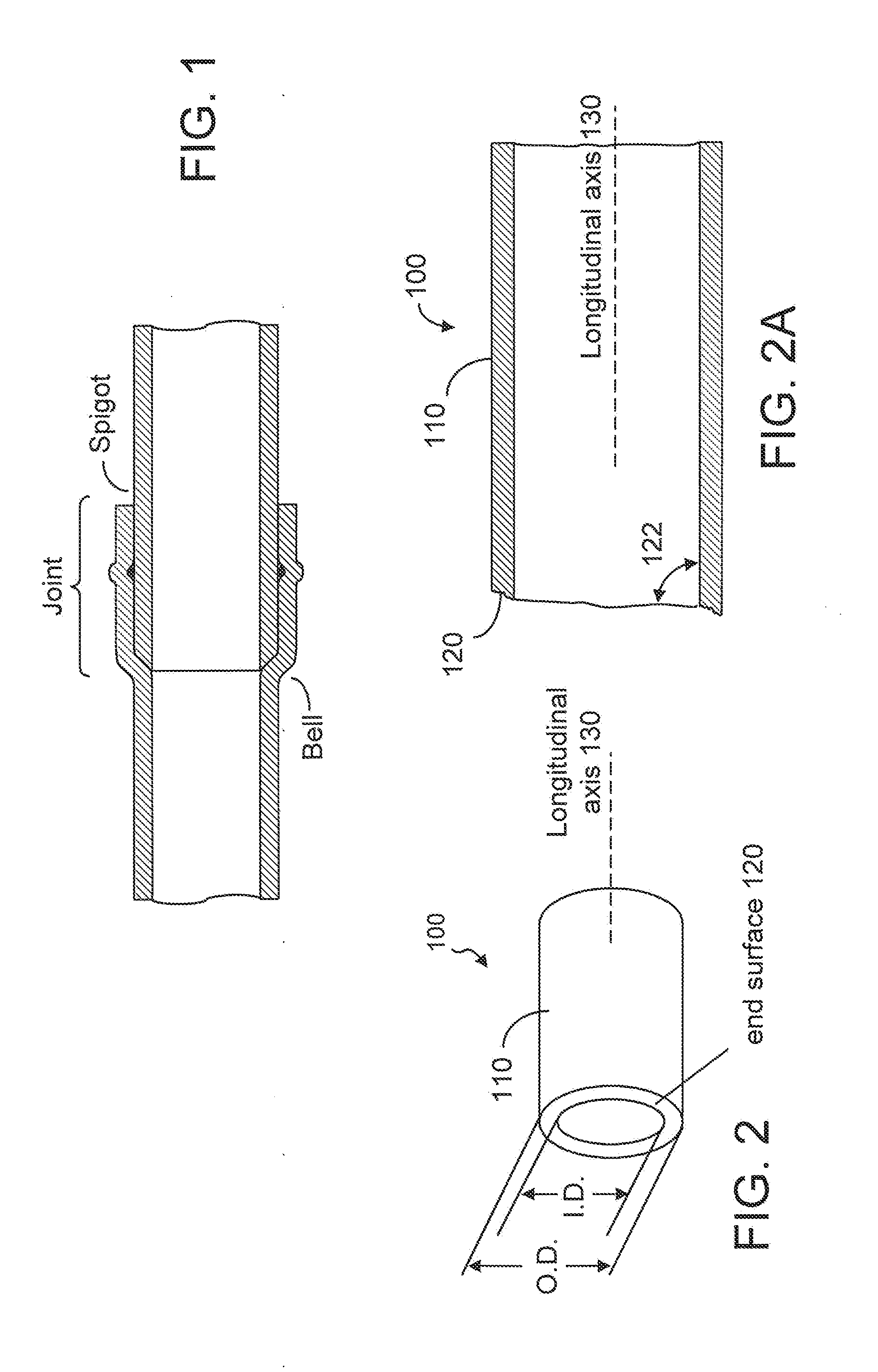
Method and Apparatus for Pipe-End Shaving
This application is based on and claims priority to U.S. Provisional Application Ser. No. 61/516,632, filed Apr. 5, 2011, and U.S. Provisional Application Ser. No. 61/518,199, filed May 2, 2011. The present invention relates generally to a pipe beveling apparatus and, more particularly, to a portable pipe beveler which can be engaged with a power tool for rotation. When a pipe is connected to another pipe, one pipe may have a hub known as a bell end and the other pipe may have a spigot end with an outer diameter dimensioned to fit the inner diameter of the bell end. As such, the spigot can be inserted into the bell end to form a joint, as shown in The present invention provides a pipe shaving apparatus for shaving off part of an end section of a pipe. The shaving apparatus has a cylindrical section and a base section connected to the cylindrical section. The cylindrical section has a cylindrical wall dimensioned to fit the outer diameter of the pipe. The cylindrical wall has a plurality of windows and a plurality of angle-cutting edges. Each of the angle-cutting edges is located at one side of the window and is bent out of the cylindrical wall, partly intruding into the inner space of the cylindrical section. As such, when the cylindrical wall is caused to rotate and the pipe is inserted into the inner space of the cylindrical wall, the angle-cutting edges shave off the outer diameter of the pipe-end section. Furthermore, the base section comprises a base plate having one or more openings and one or more front-cutting edges. The front-cutting edge is located on one side of an opening, partly bent out of the base plate toward the inner space of the cylindrical section. As such, when the pipe-end section is further inserted into the inner space of the cylindrical section, the front-cutting edges shave off the front part of the pipe-end section. Thus, the first aspect of the present invention is a pipe shaving apparatus, which comprises: a cylindrical section, a base section connected to the cylindrical section, and a drive shaft securely attached to the base section. The cylindrical section comprises a cylindrical wall having a plurality of windows and a plurality of angle-cutting edges, each edge located at one side of a window. The angle-cutting edge is bent out of the cylindrical wall, partly intruding into the inner space of the cylindrical section. The base section comprises a base plate having one or more openings and one or more front-cutting edges. The front-cutting edge is located on one side of an opening, partly bent out of the base plate toward the inner space of the cylindrical section. Furthermore, the pipe shaving apparatus also has a drive shaft securely fastened to the base plate. The drive shaft is dimensioned to be engaged with a power tool for rotation. Furthermore, the pipe shaving apparatus also has a drive shaft securely fastened to the base plate. The drive shaft is dimensioned to be engaged with a power tool for rotation. The second aspect of the present invention is a method for shaving a pipe-end section, the pipe-end section having an outer diameter and an end surface. The method comprises providing a cylindrical wall and a base plate connected to the cylindrical wall, wherein the cylindrical wall comprises a plurality of windows and the base plate comprises one or more opening, and wherein the cylindrical wall has an inner diameter dimensioned to fit the outer diameter of the pipe-end section; providing a plurality of angle-cutting edges on the cylindrical wall, each angle-cutting edge located on one side of a window; providing one or more front-cutting edges on the base plate, each front-cutting edge located on one side of an opening; causing the cylindrical wall to rotate relative to the pipe-end section and engaging the cylindrical wall with the pipe-end section such that the pipe-end section is at least inserted into part of the inner space of the cylindrical wall so as to allow one or more angle-cutting edges to shave off part of the outer diameter of the pipe-end section and to allow one or more of the front-cutting edges to shave off part of the end surface of the pipe-end section. The present invention provides a tool or apparatus for shaving off part of an end section of a pipe. As shown in The pipe shaving tool 1, according to the present invention, has a cylindrical section 8 connected to a base section 9. The shaving tool 1 is sometimes referred to as a pipe beveler. The cylindrical section 8 has a cylindrical wall 10 having an inner diameter dimensioned to fit the outer diameter of the pipe wall. The cylindrical wall 10 has a plurality of windows 12 and a plurality of angle-cutting edges 20. The base section has a base plate 40 with one or more openings 42 and one or more front-cutting edges 50. According to one embodiment of the present invention, each angle-cutting edge 20 is located on one side of a window 12, facing the window 12. Each of the openings 42 has a front-cutting edge 50 associated thereto, as shown in The resulting pipe at its pipe-end section is illustrated in In the embodiment as shown in The shaving tool 1 of the present invention, can be made of steel such as CRS 1008 and CRS 1050, but it can be made of any suitable material. The thickness of the wall can be about 0.06 inch (1.52 mm), but it can also be thinner or thicker. For example, on a pipe shaving tool to be used on a 6-inch pipe, the outer diameter of the cylindrical wall is 6.42 inches and the inner diameter is 6.30 inches. On a pipe shaving tool to be used on an 8-inch pipe, the outer diameter of the cylindrical wall is 8.55 inches and the inner diameter is 8.43 inches. The length of the cylindrical section can be 1.5 inches (38.1 mm), but it can be longer or shorter. On a pipe shaving tool to be used on a 4-inch pipe, the outer diameter of the cylindrical wall is 4.36 inches and the inner diameter is 4.25 inches. The length of the cylindrical section can be 1.25 inches (31.75 mm), but it can be longer or shorter. It should be understood by a person skilled in the art that, the physical dimensions as given above are only examples. When the tool is intended to be used on a larger pipe, the length and the thickness of the cylindrical wall could be greater. When the tool is intended to be used on a smaller pipe, the length and the thickness of the cylindrical wall could be reduced. Furthermore, in one embodiment of the present invention, the angle-cutting edges 20′ are replaceable, as shown in According to another embodiment of the present invention, the cylindrical wall has a flared end. As shown in In summary, the pipe shaving apparatus according to the present invention comprises a cylindrical section, a base section connected to the cylindrical section, and a drive shaft securely attached to the base section. The cylindrical section comprises a cylindrical wall having a plurality of windows and a plurality of angle-cutting edges, each edge located at one side of a window. The angle-cutting edge is bent out of the cylindrical wall, partly intruding into the inner space of the cylindrical section. The base section comprises a base plate having one or more openings and one or more front-cutting edges. The front-cutting edge is located on one side of an opening, partly bent out of the base plate toward the inner space of the cylindrical section. Furthermore, the pipe shaving apparatus also has a drive shaft securely fastened to the base plate. The drive shaft is dimensioned to be engaged with a power tool for rotation. The shaving tool (also known as a pipe beveler), according to the present invention, is used for two purposes. It is used to bevel the end of a pipe using a plurality of angle-cutting edges. It is also used to reface the end of the pipe using a plurality of front-cutting edges. After the pipe end is shaved with the shaving tool of the present invention, the resulting pipe has a tapered outer wall at its end. Furthermore, the end surface of the pipe is perpendicular to the longitudinal axis of the pipe. The shaving tool may have a flared portion at the open end of the cylindrical section. Thus, although the present invention has been described with respect to one or more embodiments thereof, it will be understood by those skilled in the art that the foregoing and various other changes, omissions and deviations in the form and detail thereof may be made without departing from the scope of this invention. A pipe-shaving apparatus has a cylindrical section, a base section and a drive shaft connected to the base section for rotation. The cylindrical section has a cylindrical wall dimensioned to fit the outer diameter of a pipe. The cylindrical wall has a plurality of windows and a plurality of angle-cutting edges. Each angle-cutting edge is located at the trailing side of the window. When the cylindrical wall is caused to rotate and the pipe is inserted into the inner space of the cylindrical wall, the angle-cutting edges shave off the outer diameter of the pipe-end section. The base section has one or more openings and one or more front-cutting edges located on the trailing side of the openings. When the pipe-end section is further inserted into the inner space of the cylindrical section, the front-cutting edges shave off the front part of the pipe-end section. 1. An apparatus, comprising:
a cylindrical section; a base section connected to the cylindrical section; and a drive shaft securely attached to the base section, the cylindrical section comprising a cylindrical wall having a plurality of windows and a plurality of angle-cutting edges, each angle-cutting edge located at one side of a window. 2. The apparatus according to 3. The apparatus according to 4. The apparatus according to 5. The apparatus according to 6. The apparatus according to 7. The apparatus according to 8. The apparatus according to 9. The apparatus according to 10. The apparatus according to 11. A method for shaving a pipe-end section, the pipe-end section having an outer diameter and an end surface, the method comprising:
providing a cylindrical section, and a base section connected to the cylindrical section, the cylindrical section comprising a cylindrical wall having an inner diameter dimensioned to fit the outer diameter of the pipe-end section, wherein the base section and the inner diameter of the cylindrical wall define an inner space of the cylindrical section; providing a plurality of windows on the cylindrical wall; providing a plurality of angle-cutting edges on the cylindrical wall, each of the angle-cutting edges located on one side of a window; and causing the cylindrical wall to rotate relative to the pipe-end section and engaging the cylindrical wall with the pipe-end section such that the pipe-end section is at least inserted into part of the inner space of the cylindrical wall so as to allow one or more angle-cutting edges to shave off part of the outer diameter of the pipe end section. 12. The method according to providing one or more openings on the base plate; providing one or more front-cutting edges on the base plate, each front-cutting edge located on one side of an opening, partly bent out of the base plate toward the inner space of the cylindrical section; and further engaging the cylindrical wall with the pipe-end section to allow one or more of the front-cutting edges to shave off part of the end surface of the pipe-end section. 13. The method according to 14. The method according to 15. The method according to securely attaching a drive shaft to the base plate, the drive shaft dimensioned for engagement with a power tool for causing the cylindrical wall to rotate. 16. The method according to enlarging the first end of the cylindrical wall for providing a flared portion of the cylindrical section. 17. The method according to 18. The method according to CROSS REFERENCE
FIELD OF THE INVENTION
BACKGROUND OF THE INVENTION
SUMMARY OF THE INVENTION
BRIEF DESCRIPTION OF THE DRAWINGS
DETAILED DESCRIPTION OF THE INVENTION