FUSE UNIT
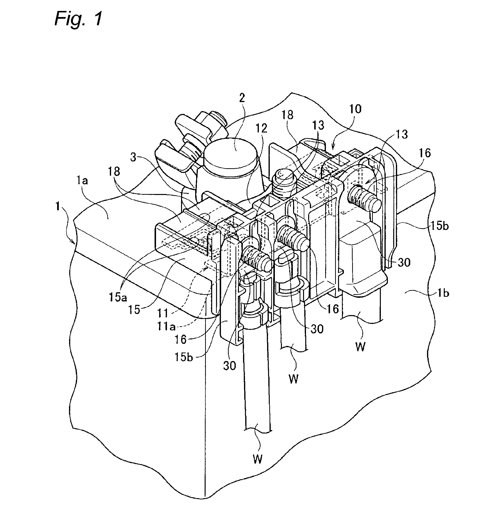
This invention is related to a fuse unit which is directly attached to a battery. For example, a fuse unit which is directly attached to a battery loaded on a vehicle has a shape which is bent almost at a right angle in consideration of a setting space or the like. One conventional example of this kind of fuse unit is explained based on As shown in The fuse unit 60 is provided with a fuse element 61 and an insulative resin part 70 which is provided outside the fuse element 61 with insertion molding. The fuse element 61 is formed of a busbar which is a conductive metal plate. The fuse element 61 has a power supply connecting part 62 which is fixed to the battery post 51 via the battery connecting terminal 52, first terminal connecting parts 63 and second terminal connecting parts 64 which are connected to terminals not shown in the figures, first terminal fusible parts 65 which respectively intervene between the power supply connecting part 62 and the first terminal connecting parts 63, and second terminal fusible parts 66 which respectively intervene between the electric supply connecting part 62 and the second terminal connecting parts 64. The power supply connecting part 62 receives power from the battery 50 via the battery connecting terminal 52. The first and second terminal connecting parts 63 and 64 have bolts 67 which are fixed with the insulative resin part 70, and the terminals (not shown in the figures) are fixed using the bolts 67. The fuse element 61 is bent between the first terminal connecting parts 63 and the second terminal fusible parts 66. Thereby, the power supply connecting part 62, the first terminal connecting parts 63 and the first terminal fusible parts 65 are arranged in the overhang direction (arrow X direction) along the upper surface 50 The insulative resin part 70 generally covers those parts other than the electric supply connecting part 62, the first and second terminal connecting parts 63 and 64, the first and second terminal fusible parts 65 and 66. Fusible part windows 70 Next, a method of manufacturing the fuse unit 60 of the above-mentioned structure is explained briefly. First, as shown in According to the above-mentioned conventional example, since the fuse unit 60 is directly attached to the battery 50 and the fuse unit 60 can be arranged along the upper surface 50 A fuse unit which is almost the same as the above-mentioned conventional example is disclosed in a PTL 1. However, in the fuse unit 60 of the above-mentioned conventional example, as shown in Since the second terminal connecting parts 64 are located below the upper surface 50 Thus, the invention is made in order to solve the above-mentioned problems, and the purpose of the invention is to provide a fuse unit which can be installed even when only a small setting space can be secured from the upper surface of a battery toward the bottom of the side surface, and which makes the connecting of terminals become easy. The above purpose of the invention is achieved with the following structures. (1) A fuse unit, comprising: a fuse element which is made of conductive metal material, and which includes a power supply connecting part fixed to a battery post of a battery so as to receive power supply and arranged along an upper surface of the battery, a terminal connecting part to which a terminal is connected, and a fusible part provided between the power supply connecting part and the terminal connecting part; and an insulative resin part that is arranged on outer surface of the fuse element, wherein the fuse element is bent upwards at a position between the power supply connecting part and the terminal connecting part, and the terminal connecting part is arranged at a position above the upper surface of the battery and along a side surface direction of the battery. (2) The fuse unit according to the above (1), wherein the fuse element is bent at a position between the fusible part and the terminal connecting part. (3) The fuse unit according to the above (1) or (2), wherein the insulative resin part has an electric wire holding part at a position below the terminal connecting part. (4) The fuse unit according to any one of the above (1) to (3), wherein a plurality of fusible parts and terminal connecting parts are provided, all the fusible parts are arranged at parallel positions of the power supply connecting part, respectively, and the fuse element is bent at positions between the fusible parts and the terminal connecting parts. Below, one embodiment of the invention is described based on the figures. As shown in The fuse unit 10 is provided with the fuse element 11 and an insulative resin part 15 which is provided outside the fuse element 11 with insertion molding. The fuse element 11 is formed of a busbar which is a conductive metal plate. The fuse element 11 has a power supply connecting part 12 which is fixed to the battery post 2 via the battery connecting terminal 3, three terminal connecting parts 13 to which terminals 30 are respectively connected, three fusible parts 14 which respectively intervene between the power supply connecting part 12 and the terminal connecting parts 13. The power supply connecting part 12 has a bolt insertion through hole 12 The three terminal connecting parts 13 are arranged at positions in parallel with each other (refer to The three fusible parts 14 are arranged at parallel positions of the power supply connecting part 12, respectively (refer to The fuse element 11 has a bent part 11 The insulative resin part 15 covers those parts other than the power supply connecting part 12, the terminal connecting parts 13, and the fusible parts 14. The power supply connecting part 12 and the terminal connecting parts 13 are exposed for the conduction between terminals, and the connection of terminals. Each of the fusible parts 14 is exposed so that whether the fusible parts 14 melt can be viewed. Fusible part windows 15 Next, a method of manufacturing the fuse unit 10 of the above-mentioned structure is explained briefly. First, as shown in Next, as shown in Next, as shown in Next, the fuse element 11 and the three bolts 16 are used as insertion components, and the insulative resin part 15 is formed with insertion molding outside the fuse element 11. Thus, the manufacture of the fuse unit 10 shown in Thus, the fuse unit 10 so manufactured is fixed to the battery post 2 via the battery connecting terminal 3. The terminals 30 are connected to the terminal connecting parts 13, respectively. Electric wires W which are connected to the terminals 30 are accommodated in the electric wire holding parts 15 As mentioned above, in the fuse unit 10 according to the embodiment, the fuse element 11 is bent upwards at the position between the fusible parts 14 and the terminal connecting parts 13, and the terminal connecting parts 13 are located above the upper surface 1 Since the terminal connecting parts 13 are arranged upwards from the upper surface 1 Since the fuse element 11 is bent at the position between the fusible parts 14 and the terminal connecting parts 13 and the fusible parts 14 are arranged on the upper surface 1 Since the insulative resin part 15 has the electric wire holding parts 15 Two or more fusible parts 14 and terminal connecting parts 13 are provided, all the fusible parts 14 are arranged at the parallel positions of the power supply connecting part 12, respectively, and the fuse element 11 is bent at the positions between the fusible parts 14 and the terminal connecting parts 13. Thus, as shown in Although the fuse unit 10 is fixed to the battery post 2 via the battery connecting terminal 3 in the embodiment, the fuse unit 10 may have a structure to be fixed to the battery post 2 without the battery connecting terminal 3. According to the embodiment, the fuse unit 10 has three terminal connecting parts 13 and three fusible parts 14, respectively. However, it is also possible that the number of the terminal connecting parts 13 and the fusible parts 14 may be one, two or more, respectively, and the number of the terminal connecting parts 13 may be different from that of the fusible parts 14. Although the present invention is described in detail with reference to the embodiments, it is apparent that various modifications and amendments may be made by those skilled in the art without departing from the spirit and scope of the invention. This application is based on the Japanese patent application (patent application 2010-027422) filed on Feb. 10, 2010, whose content is incorporated herein by reference. According to the fuse unit of the invention, since the terminal connecting parts are arranged above the upper surface of the battery, and the dimension that extends downwards from the upper surface of the battery along the side surface direction of the battery can be reduced, even when only a small setting space from the upper surface of the battery towards the bottom of the side surface of the battery can be secured, the fuse unit can be installed. Since the terminal connecting parts are arranged upwards from the upper surface of the battery, it is easy to connect the terminals. A fuse unit includes a fuse element and an insulative resin part. The fuse element includes a power supply connecting part fixed to a battery post of a battery so as to receive power supply and arranged along an upper surface of the battery, a terminal connecting part to which a terminal is connected, and a fusible part provided between the power supply connecting part and the terminal connecting part. The insulative resin part is arranged on outer surface of the fuse element. The fuse element is bent upwards at a position between the power supply connecting part and the terminal connecting part. The terminal connecting part is arranged at a position above the upper surface of the battery and along a side surface direction of the battery. 1. A fuse unit, comprising:
a fuse element which is made of conductive metal material, and which includes a power supply connecting part fixed to a battery post of a battery so as to receive power supply and arranged along an upper surface of the battery, a terminal connecting part to which a terminal is connected, and a fusible part provided between the power supply connecting part and the terminal connecting part; and an insulative resin part that is arranged on outer surface of the fuse element, wherein the fuse element is bent upwards at a position between the power supply connecting part and the terminal connecting part, and the terminal connecting part is arranged at a position above the upper surface of the battery and along a side surface direction of the battery. 2. The fuse unit according to the fuse element is bent at a position between the fusible part and the terminal connecting part. 3. The fuse unit according to the insulative resin part has an electric wire holding part at a position below the terminal connecting part. 4. The fuse unit according to a plurality of fusible parts and terminal connecting parts are provided, all the fusible parts are arranged at parallel positions of the power supply connecting part, respectively, and the fuse element is bent at positions between the fusible parts and the terminal connecting parts. TECHNICAL FIELD
BACKGROUND ART
CITATION LIST
Patent Literature
SUMMARY OF INVENTION
Technical Problem
Solution to Problem
BRIEF DESCRIPTION OF DRAWINGS
DESCRIPTION OF EMBODIMENTS
INDUSTRIAL APPLICABILITY
REFERENCE SIGNS LIST