HEATING DEVICE FOR INSTALLATION IN A SWITCHGEAR CABINET
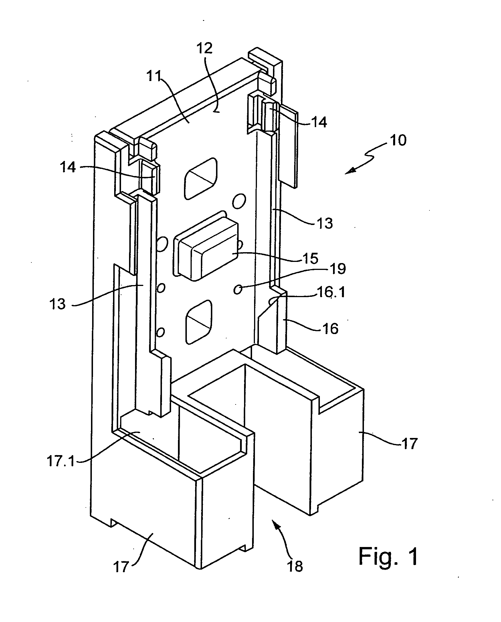
The invention relates to a heating device for installation in a switchgear cabinet, having a support and a heating body, wherein the support replaceably accommodates the heating body in a holder. Heating devices of this type are in particular used when switchgear cabinets are arranged in outdoor areas. Depending on weather conditions, it may be needed for reliable operation of the electronics accommodated in the switchgear cabinet to raise the thermal level by utilizing heating devices. Another application results when the risk of formation of condensate in the interior of the switchgear cabinet is given. The heating device is fixed in the interior of the switchgear cabinet such that the available heating power may be used accordingly. Various heating elements having the respectively needed power are available for different applications. Commonly, the heating devices are fixed to top head rails by means of mounting brackets. The mounting brackets are, on the one hand, connected with heating bodies and comprise screw bores to screw them to a top head rail or a chassis mounted within the switchgear cabinet. Heating devices of this type are known from company brochure “Rittal-Handbuch 31, Seiten 654 and 655”. It is the object of the invention to create a heating device of the type mentioned in the introductory, which may be quickly and easily installed in the interior of a switchgear cabinet and which ensures reliable fixing of the heating body. This object is solved in that the holder has a contact surface to which limiting elements are attached, in that the limiting elements immobilize the heating body in a form-fitting manner transversely to the contact surface plane and in that one or a plurality of snap-lock elements are provided in the region of the holder which immobilize the heating body within the holder. This heating device can be mounted in the interior of the switchgear cabinet such that firstly the support is coupled to a desired fixing site, for example a top head rail. Subsequently, the heating element can be inserted into the holder of the support and snapped into the snap-lock elements. Thus, toolless assembly is possible. In a locked state, the heating device is supported on the contact surface on the one hand and by the limiting elements on the other hand. Thereby, the heating body is reliably secured against translation transverse to the contact surface plane in a form-fitting manner. Reliable fixing of the heating element can be effected by this snap-lock element. According to a preferred embodiment of the invention, it may be provided that the holder comprises an interface for heating bodies of varying length which are embodied as profiled sections. Thus, the user is provided with a kit, wherein heating bodies having different heating power may be selectively attached to a holder. The heating bodies may be cut to length as profile sections from a semi-finished product at low cost. To realize this advantage, a configuration is for example suitable wherein the limiting elements are spaced apart from one another and the contact surface is arranged upright between the limiting elements. In this way, a geometry of the support results which is open in longitudinal direction of the heating bodies and allows utilization of heating bodies of varying length. The limiting elements may in particular be embodied as parallel webs, the cooling body abutting thereto via mounting bars formed thereon. By this measure, the number of different parts may be further reduced. According to a preferred variant of the invention, it may be provided that the holder comprises a protrusion engaging a recess of the heating body or that the snap-lock element engages a recess of the heating body. In a heating device according to the invention, the snap-lock elements may be arranged such that they are locked with the mounting bar which is integrally formed with the heating body and is embodied as a heat exchanger fin. On the one hand, the number of parts is reduced. On the other hand, the heating body is configured efficiency-optimized, since heating energy can also be dissipated via the mounting bars. A conceivable variant of the invention is such that two assembled bodies are attached to the holder, which are spaced apart from another and delimit a cable duct, that the cable duct provides access to an electrical terminal of the heating body and that one or both assembled bodies enclose an air-duct, which is spatially connected with an air-guiding region of the heating body. On the one hand, the two assembled bodies serve to shield the electrical terminal of the heating body. On the other hand, the assembled bodies provide the air duct to allow target-oriented air flow to the air guiding region of the heating body. The cable duct may be closed by means of a removable cover which is snap-locked to the support. The cover being removed, the electrical terminal of the heating element may easily be accessed for installation purposes. A particularly preferred variant of the invention is such that the heating body is embodied as extruded profile with integrally molded heat exchanger fin and that the heating body comprises a base part having a heating element receptacle into which the heating element is inserted. By this measure, a particularly simple and cost-effective construction for the heating body to be produced will result. In particular, the heating body may be fabricated from an extruded aluminum profile which guarantees good heat exchange characteristics. The heating element may be pressed into the heating element receptacle to allow a good heat transfer between the heating body and the heating element. If it is provided to arrange a support in the region of the holder which comprises a guiding slope inclined at an angle with respect to the contact surface, guiding the heating body into the holder during assembly, the heating body may be obliquely inserted into the holder during assembly, the guiding slope guiding the insert motion. Subsequently, the heating body is pivoted into the holder while locking with the snap-lock element. That assembly is unique and may be performed in a simple manner. A possible variant of the invention is such that the snap-lock elements immobilize the heating body perpendicularly to the contact surface in a form-fitting manner. The invention will be explained in detail below with the aid of an exemplary embodiment illustrated in the drawings. It is shown in: Contact surface 12 is bordered on both sides by two limiting elements 13. Limiting elements 13 are embodied as rib-shaped webs which are parallel spaced apart. Limiting elements 33 are discontinuous in the end region of contact surface 12 such that snap-lock elements 14 are formed. Snap-lock elements 14 are resiliently integrally coupled to support 10. They comprise an inclined deflecting slope which merges into a steep locking face arranged parallel to contact face 12. Supports 16 are connected to limiting elements 13 facing away from snap-lock elements 14. Supports 16 are embodied such that they protrude beyond limiting elements 13 in direction of the plane of contact surface 2. In this way, an undercut is formed. The undercut merges into a guidance slope 16.1 inclined at an angle <90° with respect to the surface contact plane. Two assembly bodies 17 are formed to support 10 at the end of contact surface 12 facing away from snap-lock elements 14. Assembly bodies 17 are spaced apart from another such that they laterally delimit a cable duct 18. Each of the assembly bodies 17 encloses an air duct 17.1. On the one hand, air duct 17.1 is open in a longitudinal direction of contact surface 12. On the other hand, air duct 17.1 is open towards the rear side of support 10 as may be clearly recognized in For mounting heating element 20, mounting bars 24 are brought to the guiding slopes 16.1 of support 16. The longitudinal center axis of heating body 20 is at an angle of <90° with respect to the plane of contact surface 12. Heating body 20 can be inserted into holder 11 such that mounting bars 24 slide along guiding slopes 16.1 until they reach the region of undercut of supports 16. Then, the heating body 20 may be folded down until its center longitudinal axis is parallel to contact surface 12. When folding down, protrusion 15 engages recess 23. Simultaneously, snap-lock elements 14 reach mounting bars 24 with their deflecting slopes. Resiliently suspended snap-lock elements 14 are then deviated in opposite direction, until mounting bars 24 have passed the deviating slopes. Snap-lock elements 14 then snap inwardly, wherein snap-locked faces of snap-lock elements 14 catch behind mounting bars 24. Heating body 20 is thus attached to the limiting elements 13 in transverse direction in a form-fitting manner. In longitudinal direction of the limiting elements 13, heating body 20 is held at protrusion 15 in a form-fitting manner. Offsetting the heating body 20 is prevented in a direction perpendicular to contact surface 12 by snap-lock elements 14 and undercut of supports 16. In this way, heating body 20 is reliably secured to support 10. The electrical terminal of the heating element is, in an assembled state of heating body 20, held in the region of cable duct 18. Thus, the electrical connection can be made in a simple way. Finally, cable duct 18 can be covered by a cover (which is not illustrated). During operation, the heating element transfers its heating power to heating body 20. That heating power is dissipated at heat exchanger fins 22 mainly by convection processes into the interior of the switchgear cabinet. Convection is supported by the chimney effect of air ducts 17.1. Different from the heating body of As may be further recognized in The invention relates to a heating device for installation in a switchgear cabinet, having a support and a heating body, wherein the support replaceably accommodates the heating body in a holder. Simple and secure mounting of the heating body on the support is achieved in that the holder has a contact surface to which limiting elements are attached, in that the limiting elements immobilize the heating body in a form-fitting manner transversely to the contact surface plane, and in that one or a plurality of locking elements are provided in the region of the holder, which immobilize the heating body in a form-fitting manner perpendicularly to the contact surface. 1-11. (canceled) 12. A heating device for installation in a switchgear cabinet, having a support and a heating body, wherein the support replaceably accommodates the heating body in a holder comprising a contact surface which is arranged upright between limiting elements spaced apart from another, wherein one or a plurality of snap-lock elements are provided in the region of the holder, which immobilize the heating body within the holder such that the limiting elements immobilize the heating body in a form-fitting manner transversely to the contact surface plane, wherein
the limiting elements are discontinuous in an end region of the contact surface to form the snap-lock elements, a support is arranged in the region of the holder which comprises a guiding slope inclined at an angle <90° with respect to the contact surface guiding the heating body into the holder during assembly, and the holder comprises a protrusion engaging a recess of the heating body or that the snap-lock element engages a recess of the heating body. 13. The heating device of 14. The heating device of 15. The heating device of 16. The heating device of 17. The heating device of 18. The heating device of