TERMINAL, THE TRANSMISSION POWER OF WHICH IS LIMITED IN ACCORDANCE WITH AN ADJACENT CHANNEL INTERFERENCE RATIO
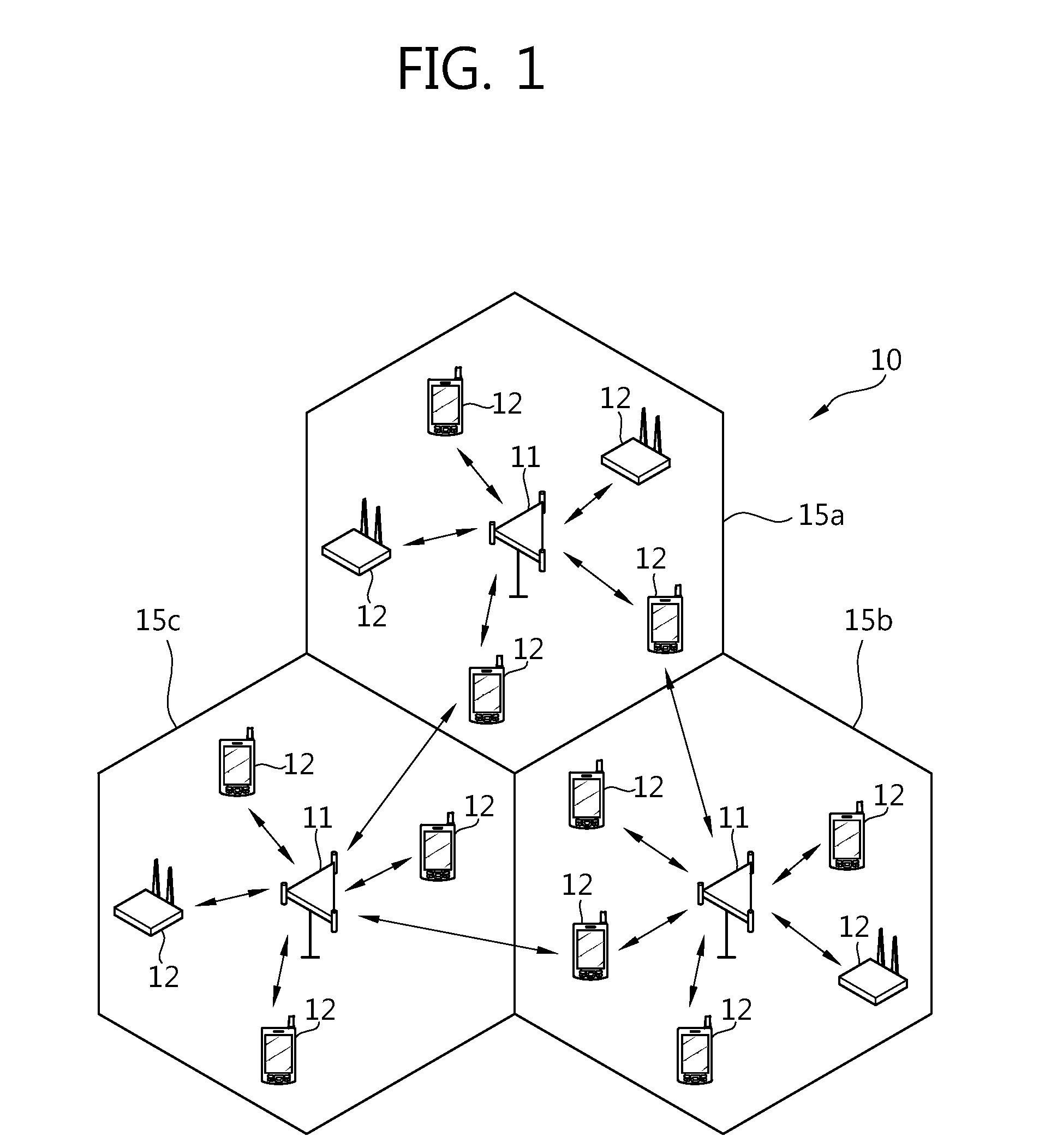
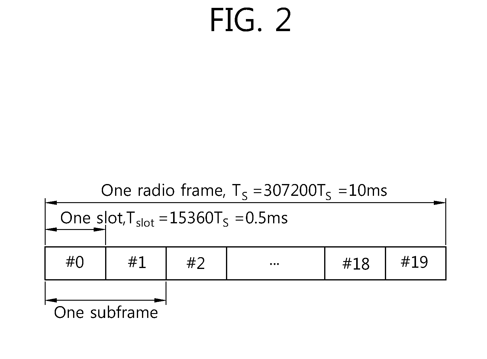
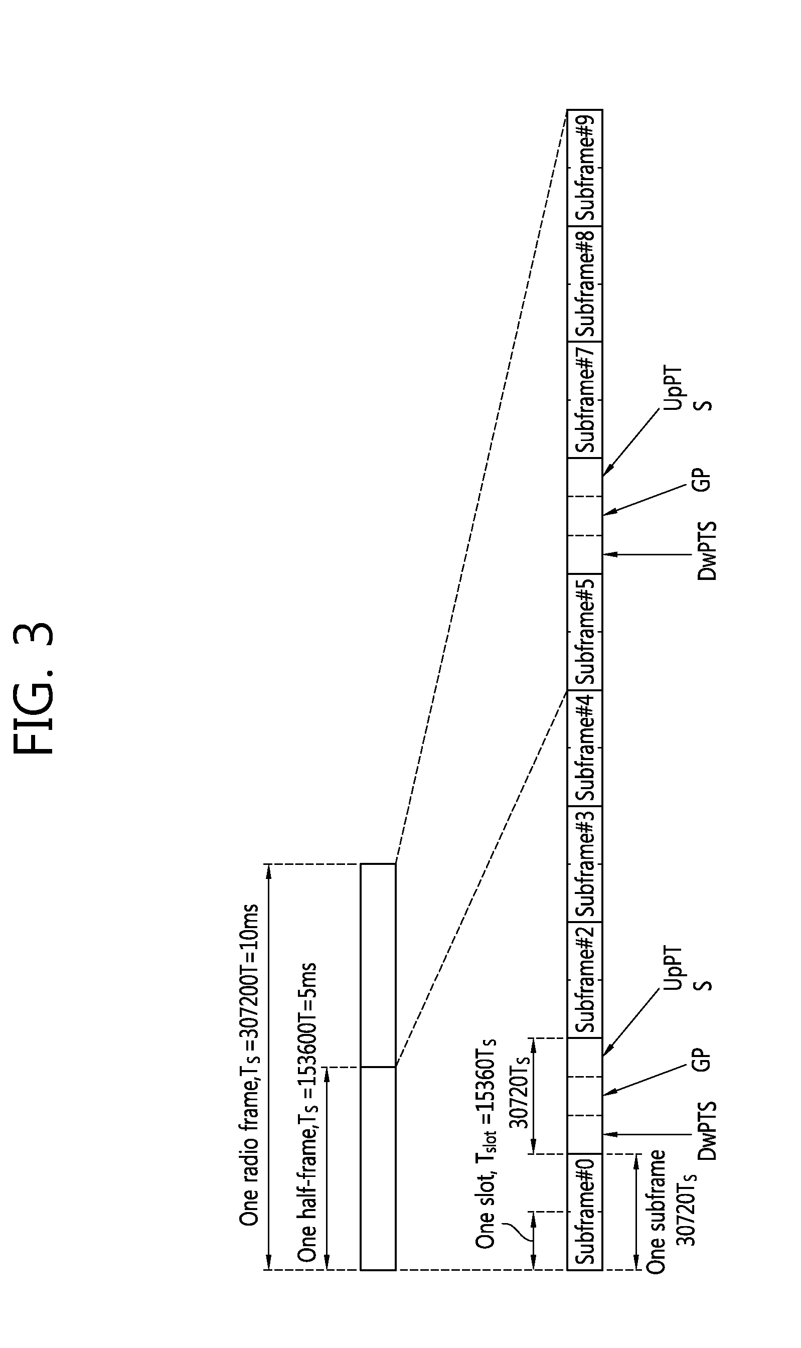
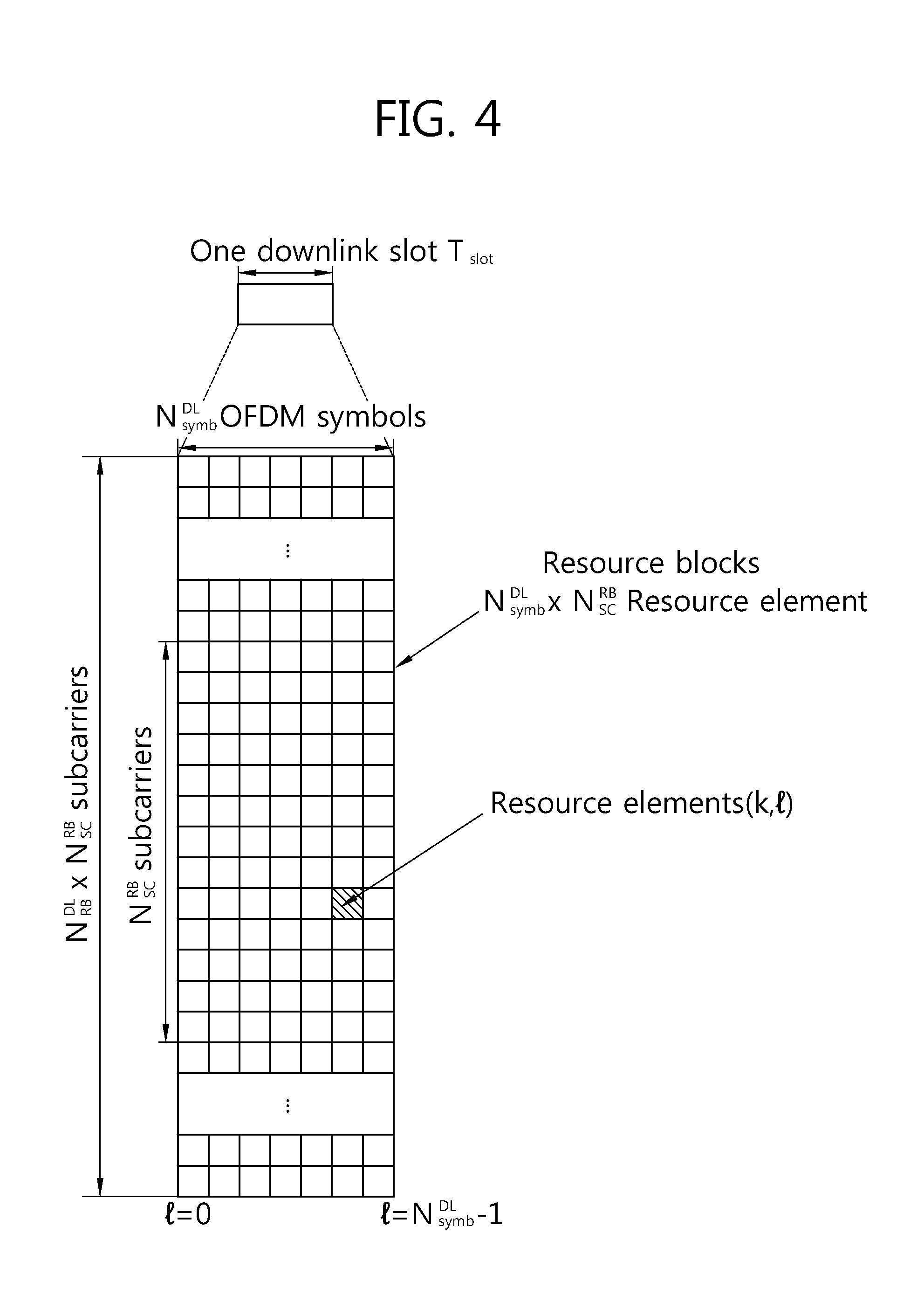
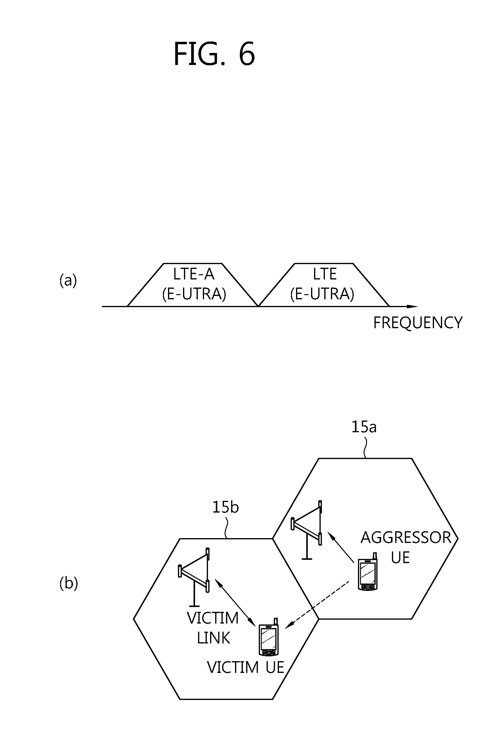
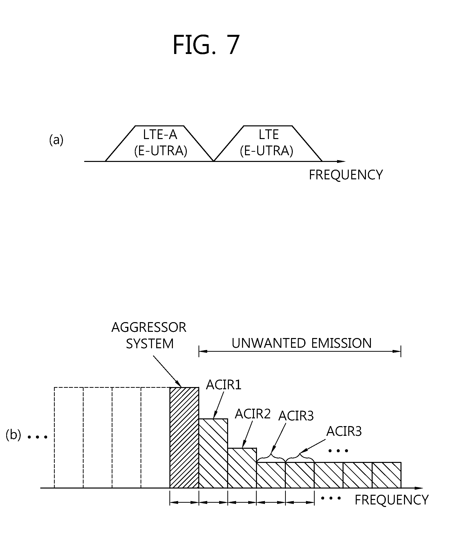
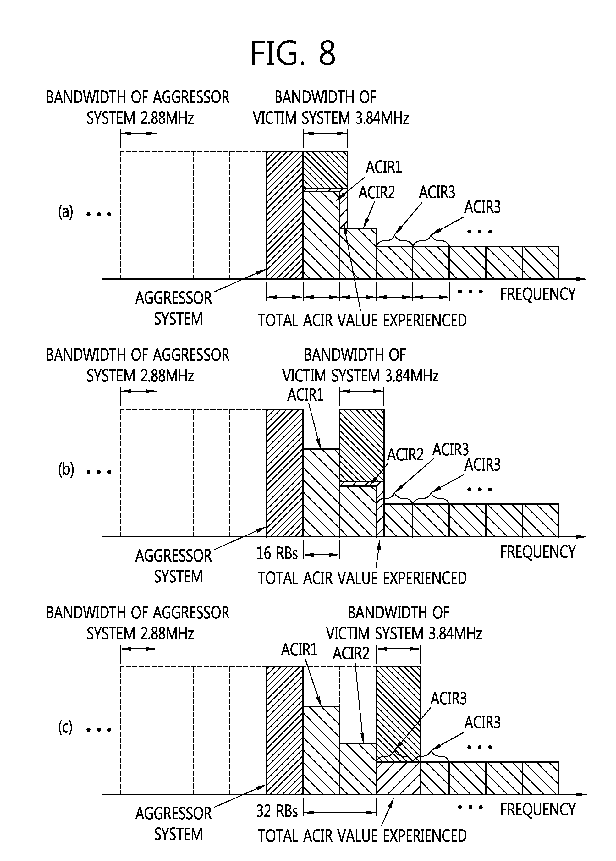
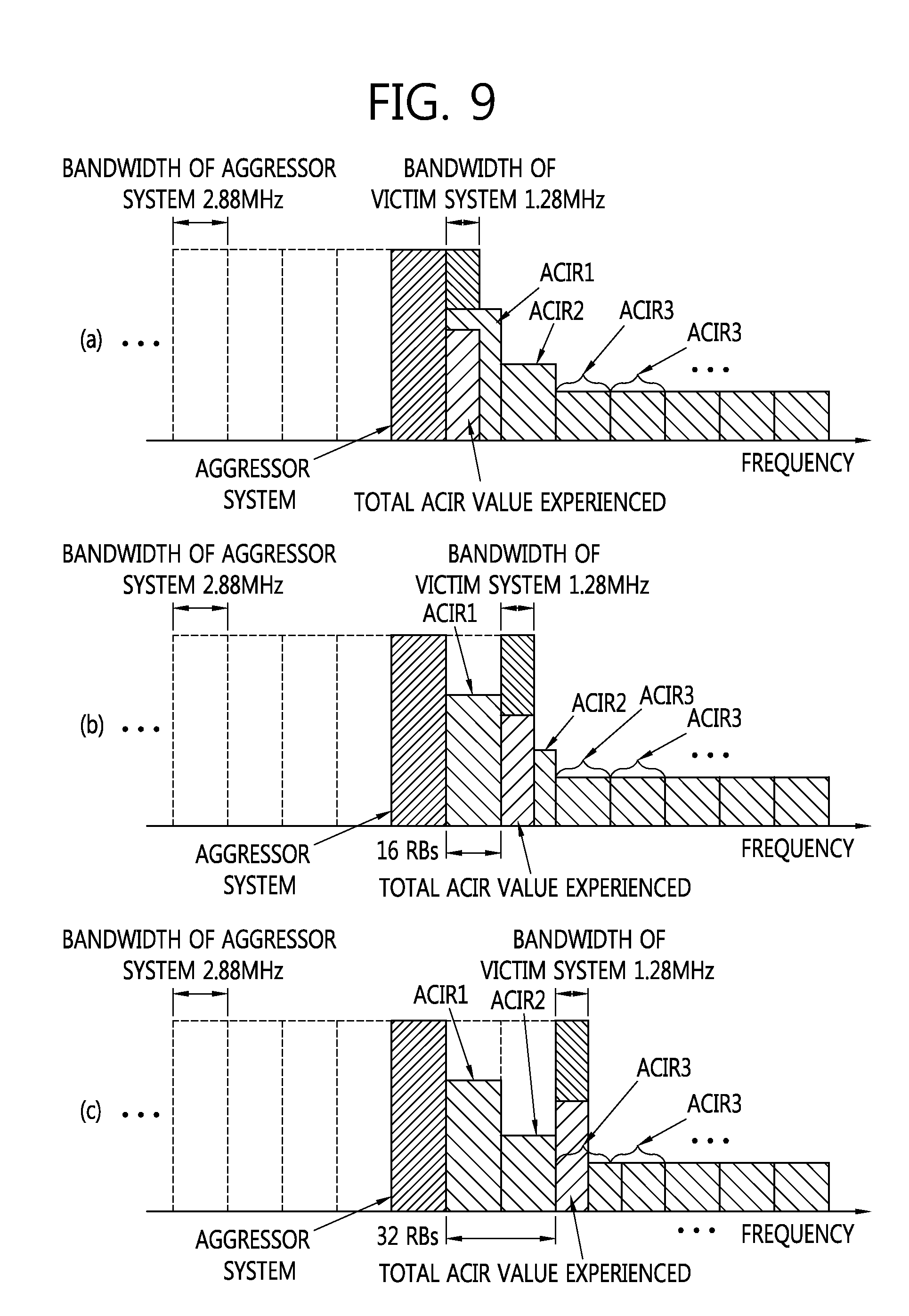
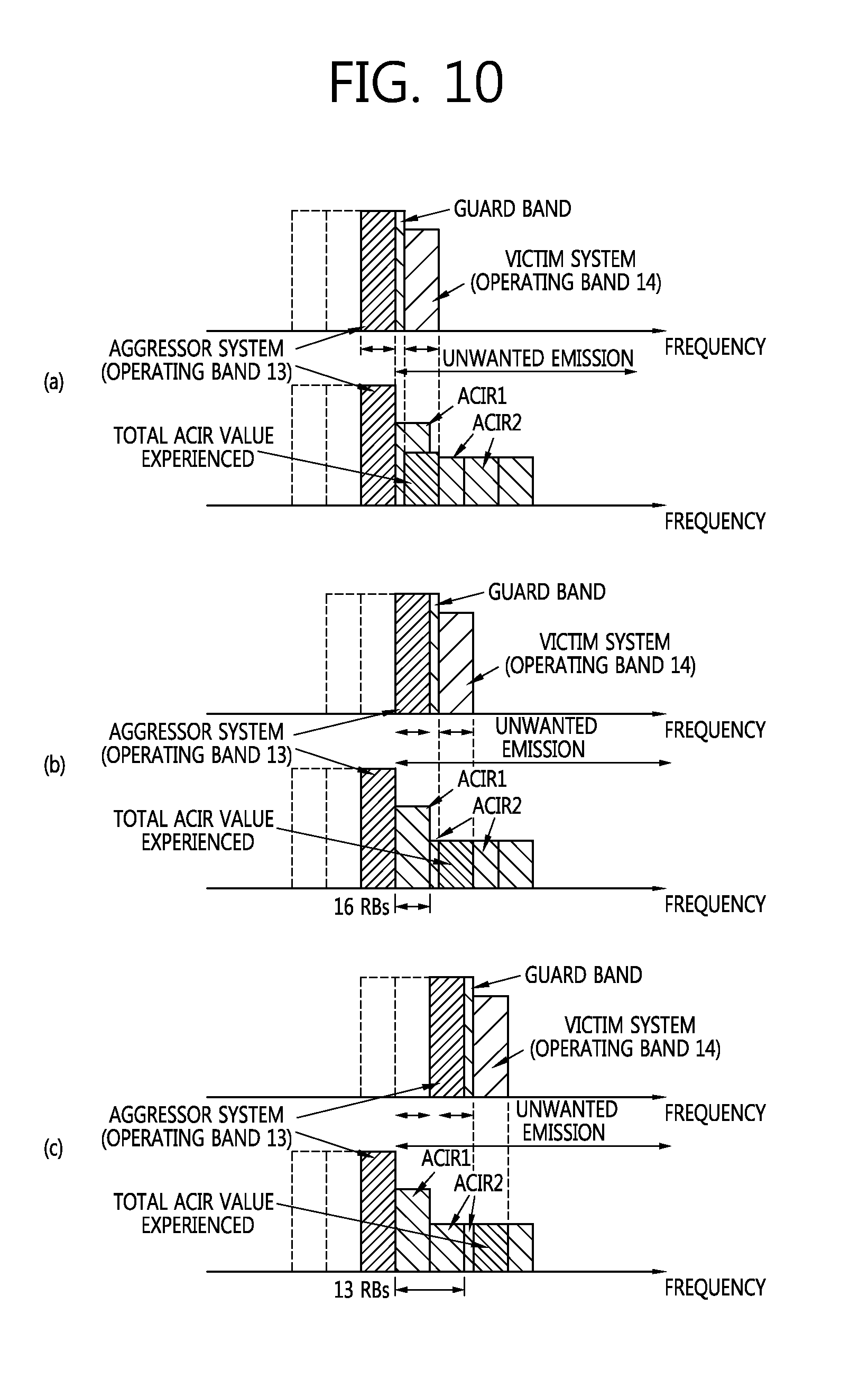
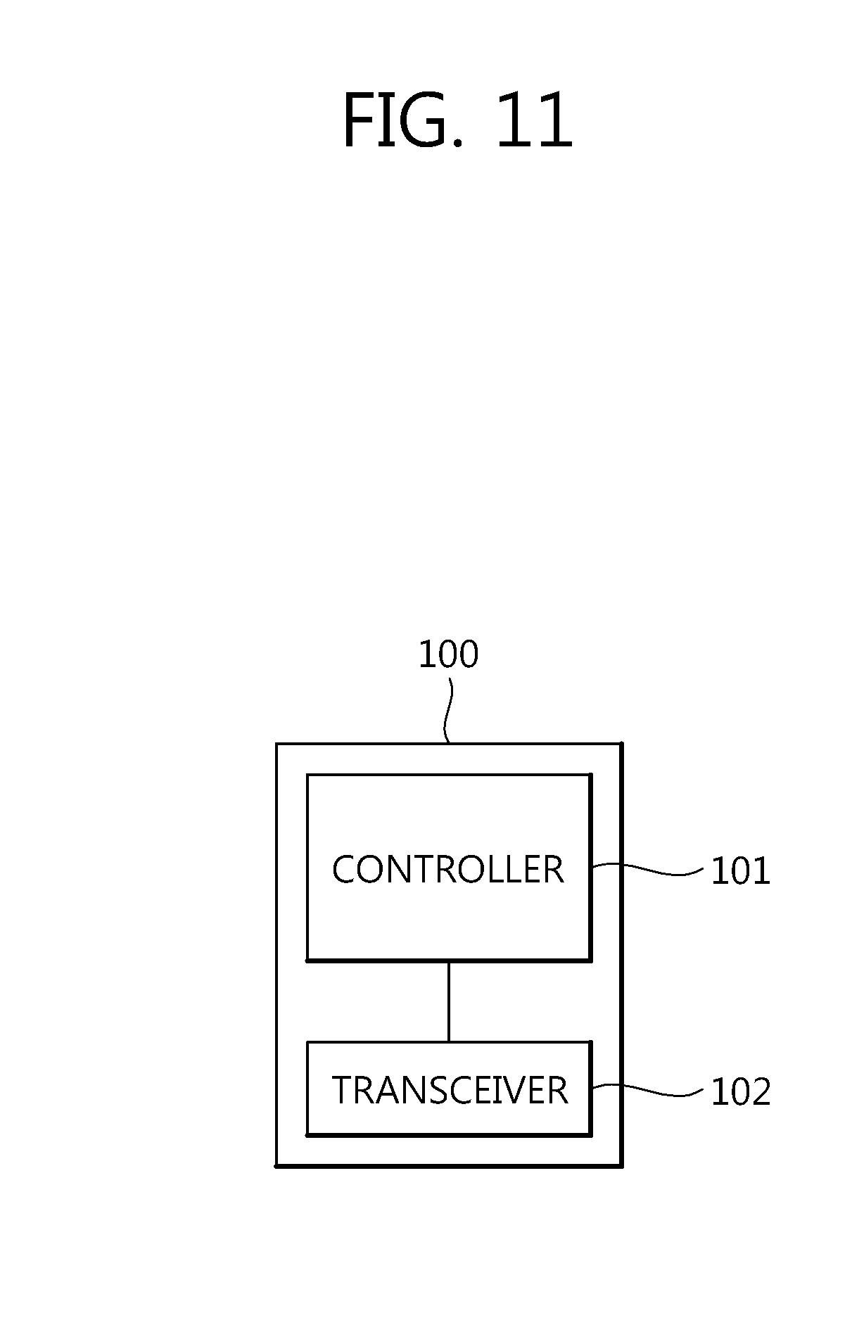
The present invention relates to a terminal having transmission power limited by an adjacent channel interference ratio. In 3rd generation mobile communication, not only voice, but also video and data can be transmitted and received. The 3rd mobile communication is required to have a higher bandwidth because data traffic suddenly increases. A task for constructing a network evolved to have a network having a higher bandwidth as described above (Long-Term Evolution Network: LTE) is in progress. In the LTE, terms: an Evolved-UMTS (E-UMTS) and an Evolved-UTRAN (E-UTRAN) are used. In the E-UTRAN, Orthogonal Frequency Division Multiple Access (OFDMA) is used as Radio Access Technology (RAT). The wireless communication system 10 includes one or more Base Stations (BSs) 11. The BS 11 commonly refers to a fixed station that communicates with User Equipments (UEs) 12, and it may also be called another terminology, such as an evolved-NodeB (eNB), a Base Transceiver System (BTS), or an access point. The BSs 11 provide communication services to respective geographical areas (commonly called cells) 15 Downlink refers to communication from a BS to UE, and uplink refers to communication from UE to a BS. In downlink, a transmitter may be part of a BS, and a receiver may be part of UE. In uplink, a transmitter may be part of UE, and a receiver may be part of a BS. LTE physical structure 3rd Generation Project Partnership (3GPP) Long Term Evolution (LTE) supports a radio frame structure of a type 1 which is applicable to Frequency Division Duplex (FDD) and a radio frame structure of a type 2 which is applicable to Time Division Duplex (TDD). In a cellular OFDM wireless packet communication system, uplink/downlink data packet transmission is performed per subframe, and one subframe is defined as specific time duration including a number of Orthogonal Frequency Division Multiplexing (OFDM) symbols. 3GPP supports a type 1 radio frame structure applicable to Frequency Division Duplex (FDD) and a type 2 radio frame structure applicable to Time Division Duplex (TDD). As shown in As shown in OFDM symbols in one downlink slot. A resource element is a resource unit that is defined by an index (k , I) within an uplink slot and a downlink slot, and it indicates one subcarrier and one OFDM symbol. Here, k is an index on a frequency axis, and I is an index on a time axis. LTE-Advanced Meanwhile, there is a discussion on the development of a system which has been more advanced from LTE and is capable of providing a higher speed transmission/reception speed. In particular, the standardization task of International Mobile Telecommunication (IMT)-Advanced, that is, the next-generation mobile communication system, is in progress. An object of IMT-Advanced is to support multimedia service based on the Internet ProtoCol (IP) at a date rate of 1 Gbps in the stop and low-speed moving states and 500 Mbps in the high-speed moving state. 3rd Generation Partnership Project (3GPP) is a system standard which satisfies the requirements of IMT-Advanced and is preparing for LTE-Advanced (LTE-A) which is improved from Long Term Evolution (LTE) and is based on Orthogonal Frequency Division Multiple Access (OFDMA)/Single Carrier-Frequency Division Multiple Access (SC-FDMA) transmission methods. LTE-Advanced is one of powerful candidates for IMT-Advanced. As described above, for higher data transmission and reception service, it is necessary to use a specific frequency band having an advantageous propagation characteristic. However, the development of new service and radio technology that use frequency bands is limited because the frequency bands are preoccupied by the existing radio service systems. Accordingly, an LTE-Advanced (or also called LTE-A) system attempts to share the frequency bands with an LTE system. If the LTE-Advanced system shares the frequency bands with the LTE system, interference may occur between the LTE-Advanced system and the LTE system. As can be seen from As can be seen from Here, a signal transmitted by the aggressor UE functions as interference to victim UE. A link between a BS and victim UE in the victim system is subject to interference, and this link is called a victim link. Accordingly, an object of the present invention is to suppress interference between systems. In other words, an object of the present invention is to suppress inter-cell interference. That is, an object of the present invention is to limit the uplink transmission power of UE in order to reduce interference in the uplink of an adjacent cell. To achieve the above objects, there is provided UE. The UE may include a transceiver unit and a control unit controlling the transceiver unit. When the transceiver unit sends a signal to a base station in an uplink band spaced apart from an uplink band used by UE within an adjacent cell by a specific band so that the uplink band of the transceiver unit is not contiguous to the uplink band used by the UE within the adjacent cell, the value of an Adjacent Channel Interference Ratio (ACIR) of the transceiver unit is limited to a value in a table below according to an offset with the specific band. The UE may be an LTE-A UE or E-UTRA UE, and the UE within the adjacent cell may be an LTE UE, an LTE-A UE, or a UTRA UE. The specific band may be a guard band. The specific band may be 1 MHz. The uplink band on which the signal is transmitted may be a band within 777 MHz to 787 MHz, and the uplink band used by the UE within the adjacent cell may be a band within 788 MHz to 798 MHz. The values of the table are calculated by an equation below, Here, the k may be a constant indicating a kth ACLR value, the BW16RB may be a bandwidth corresponding to 16 resource blocks, and the BWguard may be a bandwidth of a guard band. In order to achieve the above objects, this specification further provides UE. The UE may include a transceiver unit and a control unit controlling the transceiver unit. When the transceiver unit sends a signal to a base station in an uplink band spaced apart from an uplink band used by UE within an adjacent cell by a specific band so that the uplink band of the transceiver unit is not contiguous to the uplink band used by the UE within the adjacent cell, a value of an Adjacent Channel Interference Ratio (ACIR) of the transceiver unit is limited to a value calculated by an equation below according to an offset k with the specific band, Here, the k may be a constant indicating a kth ACLR value, the BW16RB may be a bandwidth corresponding to 16 resource blocks, and the BWguard may be a bandwidth of a guard band. The UE may be an LTE-A UE or E-UTRA UE, and the UE within the adjacent cell may be an LTE UE, an LTE-A UE, or a UTRA UE. The specific band may be a guard band, and the specific band may be 1 MHz. The values calculated by the equation are represented by a table below. In accordance with the proposal of the present invention, interference between systems is suppressed. In accordance with the disclosure of the present invention, inter-cell interference is suppressed. The present invention is applied to an LTE or LTE-A system. However, the present invention is not limited to the LTE or LTE-A system, but may be applied to all communication systems and methods to which the technical spirit of the present invention may be applied and other systems. Technical terms used in this specification are used to describe only specific embodiments, and it is to be noted that the terms are not intended to limit the present invention. Furthermore, the technical terms used in this specification should be interpreted as having meanings that are commonly understood by a person having ordinary skill in the art to which the present invention belongs, unless specifically defined in this specification, and should not be interpreted as having excessively comprehensive meanings or excessively reduced meanings. Furthermore, if the technical terms used in this specification are erroneous technical terms that do not precisely represent the spirit of the present invention, they should be replaced with technical terms that may be correctly understood by a person having ordinary skill in the art and understood. Furthermore, common terms used in the present invention should be interpreted according to the definitions of dictionaries or according to the context and should not be interpreted as having excessively reduced meanings. Furthermore, an expression of the singular number used in this specification includes an expression of the plural number unless clearly defined otherwise in the context. In this application, terms, such as “comprise” or “include”, should not be interpreted as essentially including all several elements or several steps described in the specification and should be interpreted as not including some of the elements or steps or as including additional element or steps. Furthermore, terms including ordinal numbers, such as the first and the second which are used in this specification, may be used to describe a variety of elements, but the elements should not be limited to the terms. The terms are used to only distinguish one element from the other element. For example, a first element may be named a second element and likewise a second element may be named a first element without departing the scope of the present invention. When it is said that one element is described as being “connected” or “coupled” to the other element, it should be understood that one element may be directly connected or coupled to the other element, but a third element may be interposed between the two elements. In contrast, when it is said that one element is described as being “directly connected” or “directly coupled” to the other element, it should be understood that a third element is not interposed between the two elements. Hereinafter, preferred embodiments according to the present invention are described in detail with reference to the accompanying drawings. The same or similar elements are assigned the same reference numerals irrespective of reference numerals, and a redundant description thereof is omitted. Furthermore, in describing the present invention, a detailed description of the known functions and constructions will be omitted if it is deemed to make the gist of the present invention unnecessarily vague. Furthermore, the accompanying drawings are provided to help easily understand the spirit of the present invention, and it is to be noted that the spirit of the present invention should not be limited by the spirit of the present invention. The spirit of the present invention should be interpreted as being extended up to all changes, equivalents to substitutes other than the accompanying drawings. Although User Equipment (UE) is shown, the UE may be called Customer Premise Equipment (CPE), a terminal, Mobile Equipment (ME), a Mobile Station (MS), a User Terminal (UT), a Subscriber Station (SS), a wireless device, a handheld device, or an Access Terminal (AT). Furthermore, the UE may be a portable device equipped with a communication function, such as a mobile phone, a PDA, a smart phone, a wireless modem, or a notebook, or a non-portable device, such as a PC or a device mounted on a vehicle. As can be seen from Meanwhile, if the two systems use adjacent bands on the frequency axis, for example, in Table 1 below, the aggressor system uses an operating band 18 for uplink and the victim system may use an operating band 19 for uplink. Or, the two systems may use adjacent operating bands within the operating band 18. As in An Adjacent Channel Interference Ratio, that is, an ACIR, appears. The ACIR is a ratio of total power transmitted by the transmitter (BS or UE) of an aggressor system to interference power that affects the receiver of a victim system. Accordingly, the ACIR may be represented by Paggressor-Pvictim. Here, Paggressor is the transmission power of the aggressor system, and Pvictim is interference power in the receiver of the victim system. As shown, the bandwidth of the ACIR is equal to the bandwidth of the aggressor system. A band placed just near the frequency band of the aggressor system is subject to interference that is equal to the value of an ACIR 1. The ACIR is reduced to the value of an ACIR 2 and the value of an ACIR 3 as it gradually becomes far from the aggressor system on the frequency axis. The ACIR 3 is distributed in several bands on the frequency axis. The ACIR value is shown in Table 1 below. In Table 1 above, the X is a step size for simulations (e.g., X= . . . ,−10,−5, 0, 5, 10, . . .). Meanwhile, in accordance with the first and the second scenarios in which the bandwidth of an aggressor system and the bandwidth of a victim system are identical with each other, the value of an ACIR may be calculated from an uplink ACIR value shown in Table 2 below. As can be seen from As can be seen from Furthermore, as can be seen from Furthermore, as can be seen from In the above cases, the values of the ACIRs may be summarized as in Table 4 below. As can be seen from First, as can be seen from Furthermore, as can be seen from Furthermore, as can be seen from In the above cases, the values of the ACIRs may be summarized as in Table 5 below. The scenarios described with reference to As described above with reference to In the descriptions given with reference to If there is a guard band of 1 MHz as in the operating band 13 (777 MHz-787 MHz) and the operating band 14 (788 MHz-798 MHz) of Table 1, however, there is a problem in that it is difficult to apply the above-described ACIR values. Accordingly, if a guard band exists as described above, there is a need for a new ACIR modeling method in which the guard band is taken into consideration in order to analyze a precise ACIR. Accordingly, precise ACIR values when there is a guard band between operating bands used by two systems are proposed with reference to If, as described above, an aggressor system uses the operating band 13 shown in Table 1 and a victim system uses the operating band 14 shown in Table 1, there is a guard band 1 MHz between the operating bands of the aggressor system and the victim system. This scenario may be represented by Table 7 below. Accordingly, it is necessary to calculate new ACIR values. Although an example in which the guard band 1 MHz exists between the operating band has been illustrated in First, as can be seen from In this situation, when the aggressor system (i.e., UE or CPE) sends an uplink signal, the uplink of the adjacent victim system (i.e., UE or CPE within a adjacent cell) is influenced by interference because the transmission is unnecessarily emitted to two channels adjacent to each other. That is, the channel bandwidth of the victim system is influenced by part of an ACIR1 and part of an ACIR2. The values of the ACIRs experienced by the adjacent victim system correspond to part of the ACIR 1 and part of the ACIR2, and they are 31.7 dB. This may be represented by Equation 1 below. Meanwhile, as can be seen from Meanwhile, as can be seen from Equation 1 to Equation 3 may be summarized as in Table below. Meanwhile, Equation 1 to Equation 3 may be generalized into Equation 4. In Equation 4, the k is a constant indicating a kth ACIR value, BW16RB is a bandwidth corresponding to 16 RBs, and BWguard is the bandwidth of a guard band. As described above, an aggressor system (or a primary system) gives influence to an adjacent system by an ACIR. Accordingly, the transmitter of an aggressor system, for example, a terminal or UE (or CPE) needs to be controlled when sending a signal so that the transmitter sends the signal with power less than the values of ACIRs show in Table 8 or power less than the value of an ACIR calculated by Equation 4. The above-described embodiments and modified examples may be combined. Accordingly, each of the embodiments is not implemented solely, but the embodiments may be implemented in combination at need. The combinations may be easily implemented by a person having ordinary skill in the art who reads this specification, and thus a detailed description thereof is omitted. It is however to be noted that although the combinations are not described, they are not excluded from the present invention, but should be interpreted as being included in the scope of the present invention. The above-described embodiments and modified examples may be implemented through a variety of means. For example, the embodiments of the present invention may be implemented by hardware, firmware, software, or a combination of them. In the case of implementations using hardware, a method according to the embodiments of the present invention may be implemented by one or more Application Specific Integrated Circuits (ASICs), Digital Signal Processors (DSPs), Digital Signal Processing Devices (DSPDs), Programmable Logic Devices (PLDs), Field Programmable Gate Arrays (FPGAs), processors, controllers, micro controllers, micro processors, etc. In the case of implementations using firmware or software, a method according to the embodiments of the present invention may be implemented in the form of a module, a procedure, or function that performs the above-described functions or operations. A software code may be stored in a memory unit and driven by a processor. The memory unit may be placed inside or outside the processor, and it may exchange data with the processor through a variety of known means. For example, the methods in accordance with the present invention may be stored in a storage medium (e.g., internal memory, flash memory, or a hard disk) and may be implemented using codes or instructions within a software program that may be executed by a processor (e.g., a micro processor). This is described below with reference to As shown in The controller 101 controls the transceiver unit 102. More particularly, the controller 101 performs control when the transceiver unit 102 sends a signal so that the transceiver unit 102 sends the signal with power less than the values of ACIRs shown in Table 8 or power less than the value of an ACIR calculated by Equation 4. The above-described embodiments are results in which the elements and characteristics of the present invention are combined in a specific form. Each of the element or characteristics has to be considered as being optional unless otherwise explicitly described. Each of the elements or characteristics may be implemented in such a way as not to be combined with other elements or characteristics. Furthermore, some of the elements and/or the characteristics may be combined to form an embodiment of the present invention. Order of the operations described in the embodiments of the present invention may be changed. Some of the elements or characteristics of one embodiment may be included in the other embodiment or may be replaced with elements or characteristics corresponding to the other embodiment. It is evident that in the claims, embodiments may be constructed by combining claims not having an explicit citation relation or the claims not having an explicit citation relation may be included in a new claim according to amendments after an application. The present invention ma y be materialized in a specific form without departing from the spirit and essential characteristics of the present invention. Accordingly, the detailed description should not be interpreted as being limited from all aspects, but should be considered as being illustrative. The scope of the present invention should be determined by reasonable analysis of the attached claims, and all changes within an equivalent range of the present invention fall within the scope of the present invention. Furthermore, in the claims, embodiments may be constructed by combining claims not having an explicit citation relation or the claims not having an explicit citation relation may be included in a new claim according to amendments after an application. The present description relates to a terminal. The terminal comprises: a transceiving unit; and a control unit which controls the transceiving unit. When transmitting a signal in an uplink band that is spaced apart by a predetermined band so as to avoid continuity with the uplink band used by a terminal in an adjacent cell, the transceiving unit has an adjacent channel interference ratio, the value of which can be limited to a preset value in accordance with an offset relative to a predetermined band. 1. User equipment (UE), comprising:
a transceiver unit; a control unit controlling the transceiver unit, wherein when the transceiver unit sends a signal to a base station in an uplink band spaced apart from an uplink band used by UE within an adjacent cell by a specific band so that the uplink band of the transceiver unit is not contiguous to the uplink band used by the UE within the adjacent cell, a value of an Adjacent Channel Interference Ratio (ACIR) of the transceiver unit is limited to a value in a table below according to an offset with the specific band. 2. The UE of the UE is an LTE-A UE or E-UTRA UE, and the UE within the adjacent cell is an LTE UE, an LTE-A UE, or a UTRA UE. 3. The UE of 4. The UE of 5. The UE of the uplink band on which the signal is transmitted is a band within 777 MHz to 787 MHz, and the uplink band used by the UE within the adjacent cell is a band within 788 MHz to 798 MHz. 6. The UE of wherein the k is a constant indicating a kth ACLR value, the BW16RB is a bandwidth corresponding to 16 resource blocks, and the BWguard is a bandwidth of a guard band. 7. User equipment (UE), comprising:
a transceiver unit; a control unit controlling the transceiver unit, wherein when the transceiver unit sends a signal to a base station in an uplink band spaced apart from an uplink band used by UE within an adjacent cell by a specific band so that the uplink band of the transceiver unit is not contiguous to the uplink band used by the UE within the adjacent cell, a value of an Adjacent Channel Interference Ratio (ACIR) of the transceiver unit is limited to values calculated by an equation below according to an offset k with the specific band. wherein the k is a constant indicating a kth ACLR value, the BW16RB is a bandwidth corresponding to 16 resource blocks, and the BWguard is a bandwidth of a guard band. 8. The UE of the UE is an LTE-A UE or E-UTRA UE, and the UE within the adjacent cell is an LTE UE, an LTE-A UE, or a UTRA UE. 9. The UE of 10. The UE of 11. The UE of the uplink band on which the signal is transmitted is a band within 777 MHz to 787 MHz, and the uplink band used by the UE within the adjacent cell is a band within 788 MHz to 798 MHz. 12. The UE of TECHNICAL FIELD
BACKGROUND ART
DISCLOSURE
Technical Problem
Technical Solution
0 RB 32 + X (X = . . . , −10, −5, 0, . 5, 10, . . . dB) 16 RBs 43 + X (X = . . . , −10, −5, 0, . 5, 10, . . . dB) 32 RBs or more 43 + X (X = . . . , −10, −5, 0, . 5, 10, . . . dB) 0 RB 32 + X (X = . . . , −10, −5, 0, . 5, 10, . . . dB) 16 RBs 43 + X (X = . . . , −10, −5, 0, . 5, 10, . . . dB) 32 RBs or more 43 + X (X = . . . , −10, −5, 0, . 5, 10, . . . dB) Advantageous Effects
DESCRIPTION OF DRAWINGS
MODE FOR INVENTION
1 1920 MHz-1980 MHz 2110 MHz-2170 MHz FDD 2 1850 MHz-1910 MHz 1930 MHz-1990 MHz FDD 3 1710 MHz-1785 MHz 1805 MHz-1880 MHz FDD 4 1710 MHz-1755 MHz 2110 MHz-2155 MHz FDD 5 824 MHz-849 MHz 869 MHz-894 MHz FDD 6 830 MHz-840 MHz 875 MHz-885 MHz FDD 7 2500 MHz-2570 MHz 2620 MHz-2690 MHz FDD 8 880 MHz-915 MHz 925 MHz-960 MHz FDD 9 1749.9 MHz-1784.9 MHz 1844.9 MHz-1879.9 MHz FDD 10 1710 MHz-1770 MHz 2110 MHz-2170 MHz FDD 11 1427.9 MHz-1447.9 MHz 1475.9 MHz-1495.9 MHz FDD 12 699 MHZ-716 MHz 729 MHz-746 MHz FDD 13 777 MHz-787 MHz 746 MHz-756 MHz FDD 14 788 MHz-798 MHz 758 MHz-768 MHz FDD 15 reserved reserved FDD 16 reserved reserved FDD 17 704 MHz-716 MHz 734 MHz-746 MHz FDD 18 815 MHz-830 MHz 860 MHz-875 MHz FDD 19 830 MHz-845 MHz 875 MHz-890 MHz FDD 20 832 MHz-862 MHz 791 MHz-821 MHz FDD 21 1447.9 MHz-1462.9 MHz 1495.9 MHz-1510.9 MHz FDD . . . 24 1626.5 MHz-1660.5 MHz 1525 MHz-1559 MHz FDD . . . 33 1900 MHz-1920 MHz 1900 MHz-1920 MHz TDD 34 2010 MHz-2025 MHz 2010 MHz-2025 MHz TDD 35 1850 MHz-1910 MHz 1850 MHz-1910 MHz TDD 36 1930 MHz-1990 MHz 1930 MHz-1990 MHz TDD 37 1910 MHz-1930 MHz 1910 MHz-1930 MHz TDD 38 2570 MHz-2620 MHz 2570 MHz-2620 MHz TDD 39 1880 MHz-1920 MHz 1880 MHz-1920 MHz TDD 40 2300 MHz-2400 MHz 2300 MHz-2400 MHz TDD 41 2496 MHz-2690 MHz 2496 MHz 2690 MHz TDD 42 3400 MHz-3600 MHz 3400 MHz-3600 MHz TDD 43 3600 MHz-3800 MHz 3600 MHz-3800 MHz TDD ACIR 1 30 + X 30 + X ACIR 2 43 + X 43 + X ACIR 3 50 + X 43 + X 0 RB 30 + X 16 RBs 43 + X 32 RBs or more 50 + X 0 RB 30 + X 16 RBs 43 + X 32 RBs or more 49 + X 0 RB 33.5 + X 16 RBs 46.5 + X 32 RBs or more 53.5 + X 1 DL: 40 MHz, UL: 40 MHz LTE-A 10 MHz LTE 2 DL: 40 MHz, UL: 40 MHz LTE-A DL: 40 MHz, UL: 40 MHz LTE-A 3 DL: 40 MHz, UL: 40 MHz LTE-A 5 MHz UTRA FDD 4 DL: 40 MHz, UL: 40 MHz LTE-A 1.6 MHz UTRA TDD 5 DL: 10 MHz, UL: 10 MHz LTE/CPE 10 MHz LTE 0 RB 32 + X 16 RBs 43 + X 32 RBs or more 43 + X 0 RB 32 + X (X = . . . , −10, −5, 0, . 5, 10, . . . dB) 16 RBs 43 + X (X = . . . , −10, −5, 0, . 5, 10, . . . dB) 32 RBs or more 43 + X (X = . . . , −10, −5, 0, . 5, 10, . . . dB) 0 RB 32 + X (X = . . . , −10, −5, 0, . 5, 10, . . . dB) 16 RBs 43 + X (X = . . . , −10, −5, 0, . 5, 10, . . . dB) 32 RBs or more 43 + X (X = . . . , −10, −5, 0, . 5, 10, . . . dB)