CLEANING DEVICE FOR CLEANING OPTICAL LENSES IN TRAY
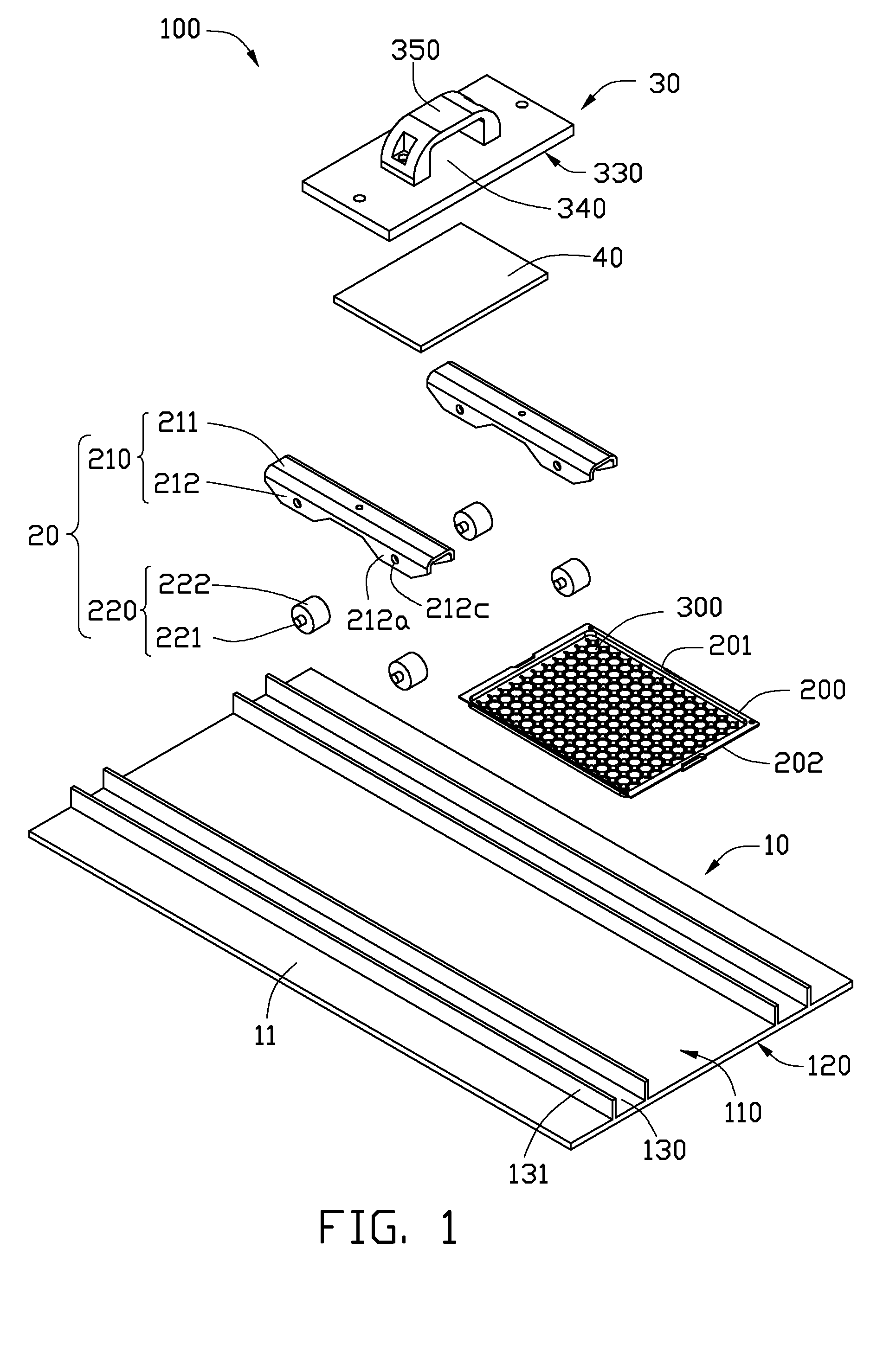
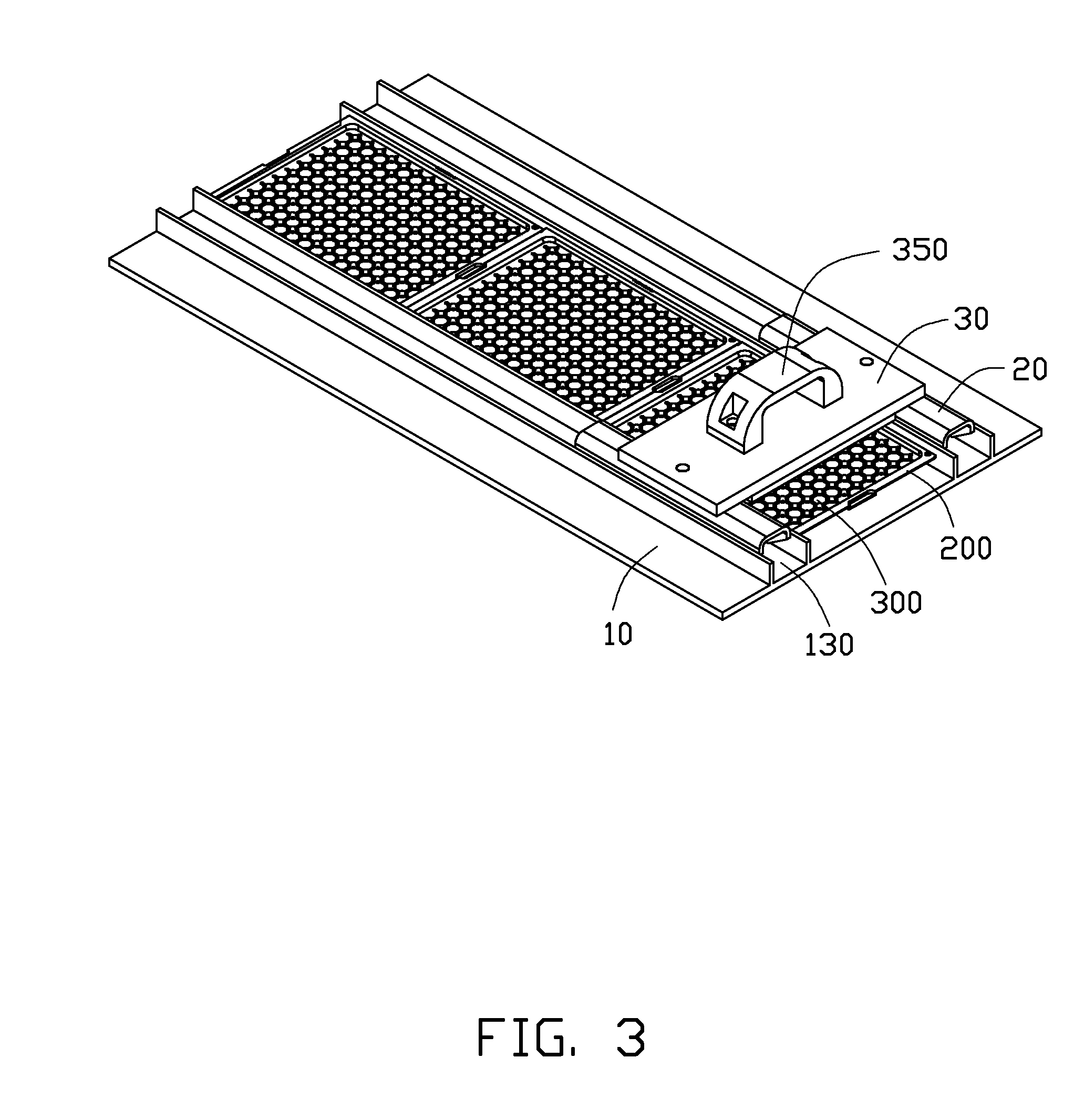
1. Technical Field The present disclosure relates to cleaning devices, and particularly, relates to a cleaning device for cleaning optical lenses held in a tray. 2. Description of Related Art Optical lenses are the main optical elements in a lens module and can be made of plastic by injection molding. When optical lenses are molded, the optical lenses are held in a tray for transportation. However, during the displacement of the transportation, the lenses may be stained by iron pollutant, which may decrease optical quality of the optical lenses. What is needed therefore is a cleaning device addressing the limitations described. The components of the drawings are not necessarily drawn to scale, the emphasis instead being placed upon clearly illustrating the principles of the embodiments of the present disclosure. Moreover, in the drawings, like reference numerals designate corresponding parts throughout several views. Referring to The cleaning device 100 includes a supporting base 10, two sliding members 20, a connecting plate 30, and a magnetic member 40. The supporting base 10 is configured for supporting the tray 200. The supporting base 10 includes a bottom plate 11 and two rails 130 substantially parallel to each other. The bottom plate 11 is substantially rectangular. The bottom plate 11 includes a first surface 110 and a second surface 120 opposite to the first surface 110. The rails 130 are spatially corresponding to the sliding members 20. The rails 130 are formed on the first surface 110 of the bottom plate 11. Each rail 130 includes two parallel guiding strips 131. In this embodiment, the rails 130 are integrated with the bottom plate 11. The tray 200 is accommodated between the rails 130. In this embodiment, the perpendicular distance between the rails 130 is larger than a length of each first side bar 201 or a length of each second side bar 202. Each sliding member 20 is slidably connected to a corresponding rail 130. Each sliding member 20 includes a connecting member 210 and two wheels 220 rotatably connected to the connecting member 210. The connecting member 210 includes a top plate 211 and two side plates 212 substantially perpendicular to the top plate 211. Each side plate 212 includes two protruded connecting portions 212 A perpendicular distance of outer surfaces of the side plates 212 of each sliding member 20 is slightly less than a perpendicular distance of inner surfaces of the guiding strips 131 of each rail 130, thus the sliding member 20 can be fittedly and slidably mounted between the strips 131. The strips 131 restrict the sliding member 20 to slide along the rail 130. In this embodiment, each connecting member 210 connects to two wheels 220, and the number of the connecting portions 212 The connecting plate 30 is supported on the sliding members 20. The connecting plate 30 includes a third surface 330 facing toward the first surface 110 of the bottom plate 11 and a fourth surface 340 opposite to the third surface 330. The connecting plate 30 further includes a handle 350 formed on the fourth surface 330. A force can acted on the handle 350 to move the connecting plate 30. Two opposite ends of the connecting plate 30 are fixedly connected to the sliding member 20, respectively. The magnetic member 40 is fixedly attached on the third surface 330 of the connecting plate 30. In this embodiment, the magnetic member 40 is substantially rectangular. A length of the magnetic member 40 along a direction perpendicular to the rails 130 and parallel to the bottom plate 11 is slightly less than the distance between the rails 130. In this embodiment, the magnetic member 40 is a piece of magnet. Referring also to It is believed that the present embodiments and their advantages will be understood from the foregoing description, and it will be apparent that various changes may be made thereto without departing from the spirit and scope of the disclosure or sacrificing all of its material advantages, the examples hereinbefore described merely being preferred or exemplary embodiments of the disclosure. Provided is a cleaning device for cleaning optical lenses positioned in a tray. The cleaning device includes a supporting base for supporting the tray, two sliding members, a connecting plate, and a magnetic member. The supporting base includes a bottom plate and two parallel rails formed on a surface of the bottom plate. The sliding members are spatially corresponding to the rails, and each sliding member is slidably mounted on a corresponding one of the rails. The connecting plate is fixedly supported on the sliding members. The magnetic member is attached on a surface of the connecting plate facing toward the bottom plate. 1. A cleaning device for cleaning optical lenses positioned in a tray, comprising:
a supporting base for supporting the tray, the supporting base comprising a bottom plate and two parallel rails on a surface of the bottom plate; two sliding members spatially corresponding to the rails respectively, each sliding member being slidably mounted on a corresponding one of the rails; a connecting plate fixedly supported on the sliding members; and a magnetic member attached on a surface of the connecting plate and facing toward the bottom plate. 2. The cleaning device of 3. The cleaning device of 4. The cleaning device of 5. The cleaning device of 6. The cleaning device of 7. The cleaning device of 8. The cleaning device of 9. The cleaning device of BACKGROUND
BRIEF DESCRIPTION OF THE DRAWINGS
DETAILED DESCRIPTION