TUBE AND BAFFLE ARRANGEMENT IN A ONCE-THROUGH HORIZONTAL EVAPORATOR
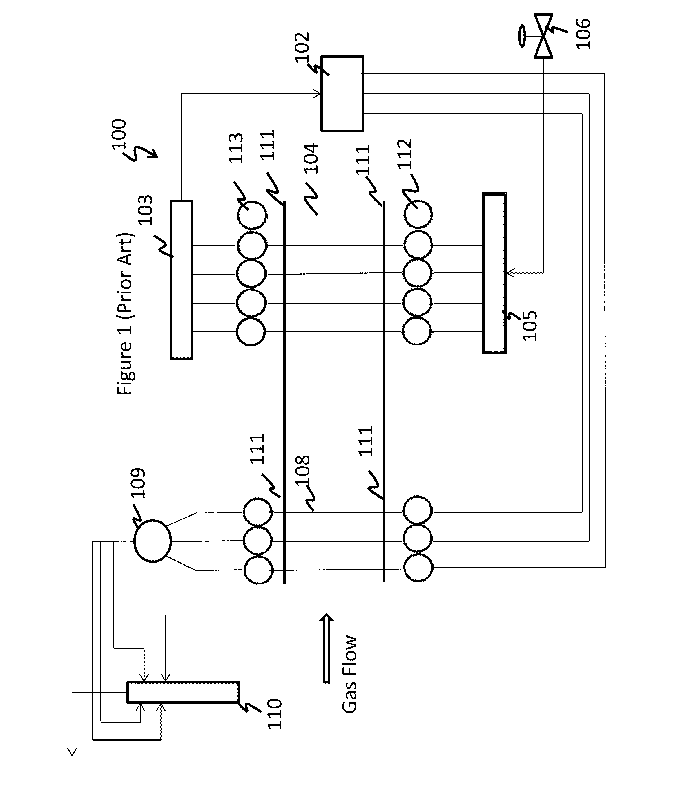
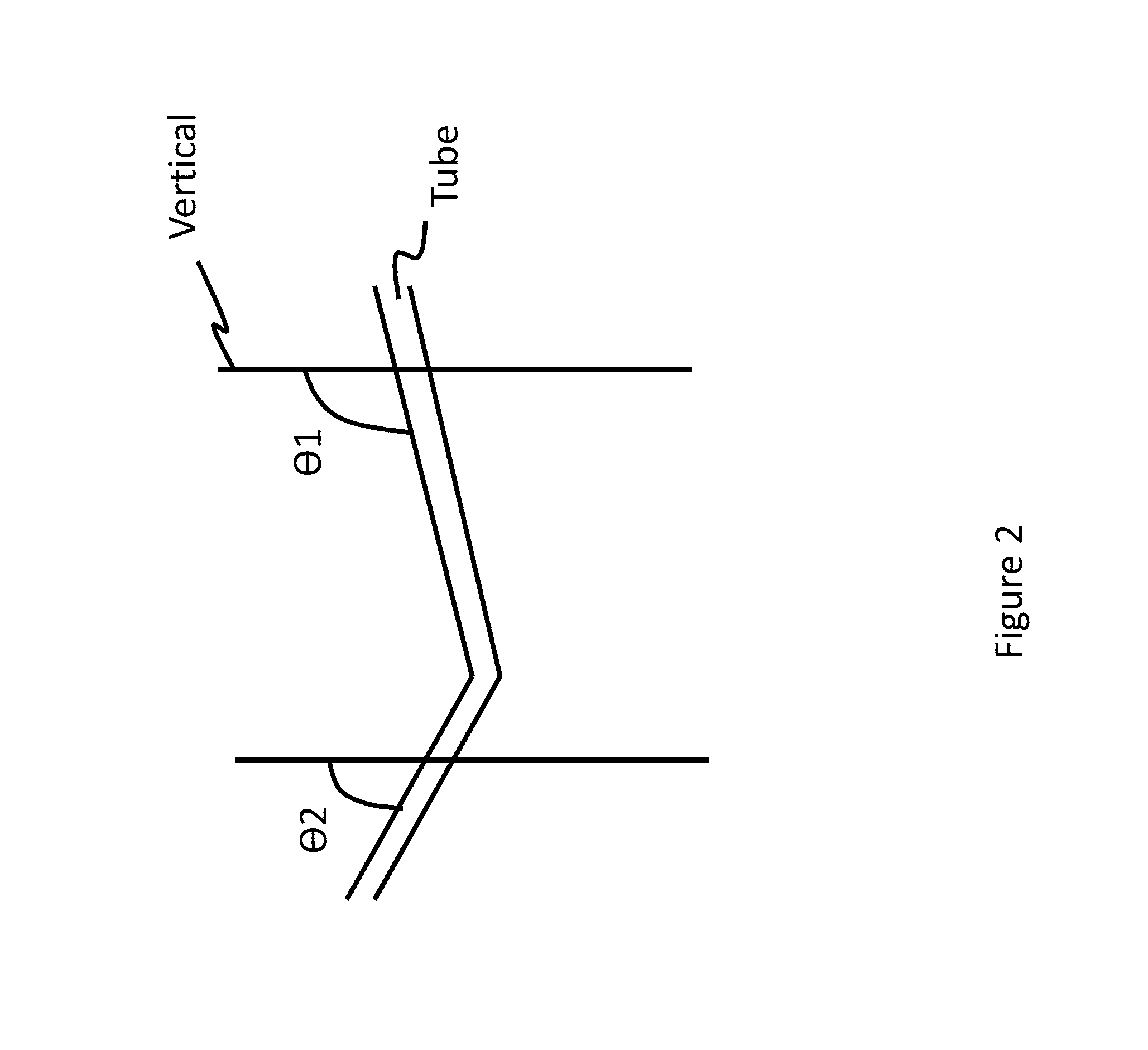
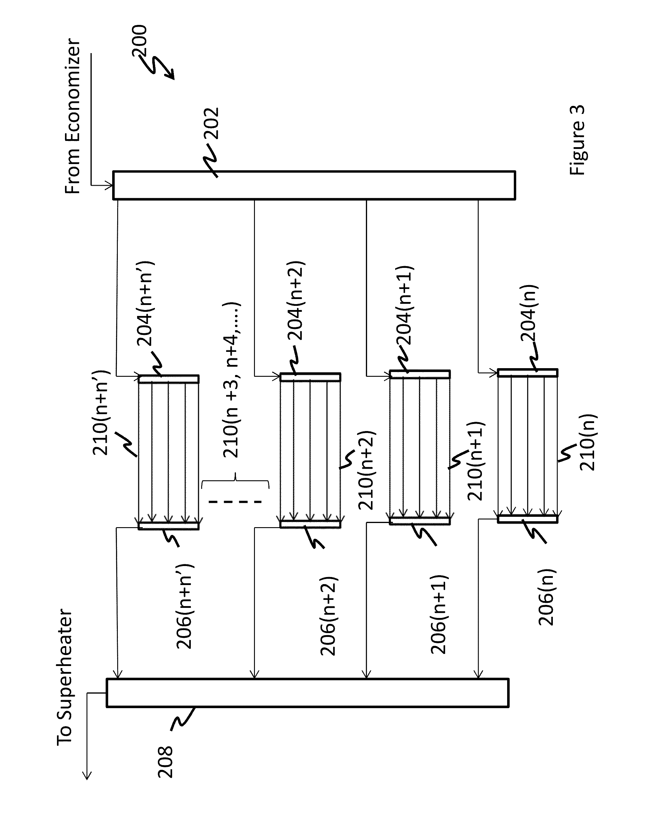
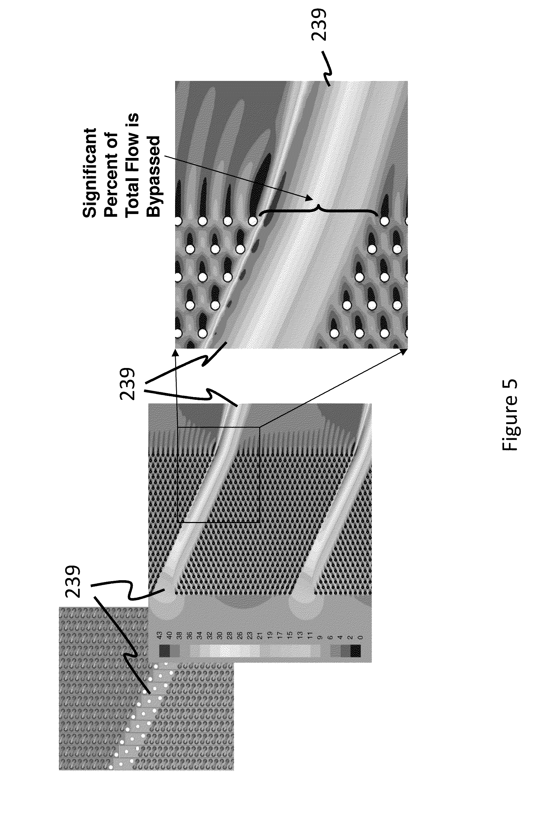
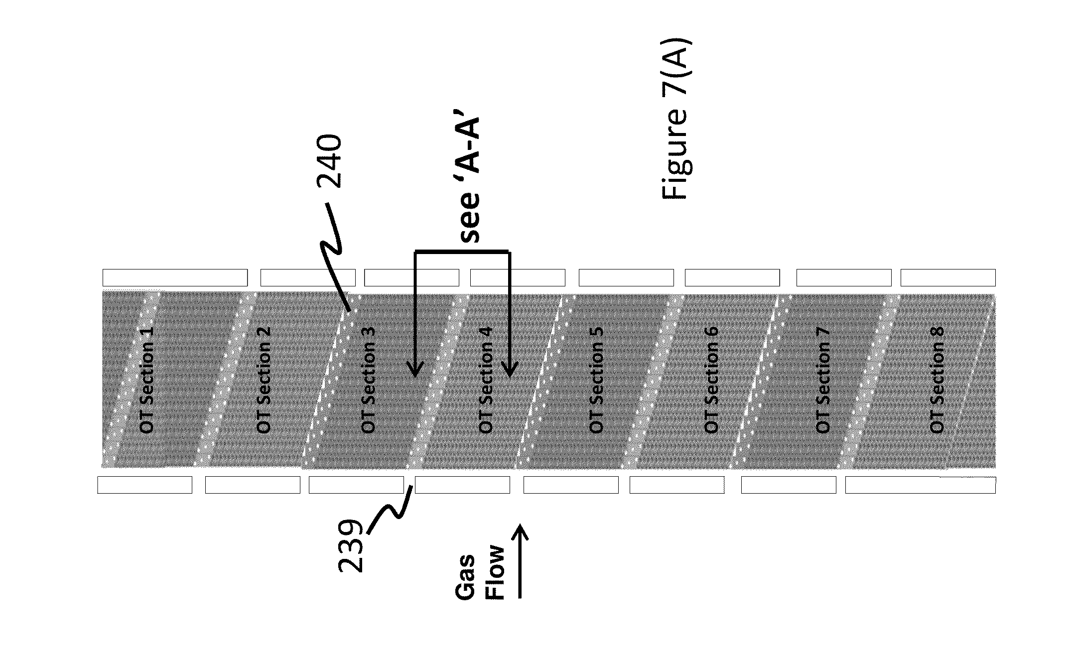
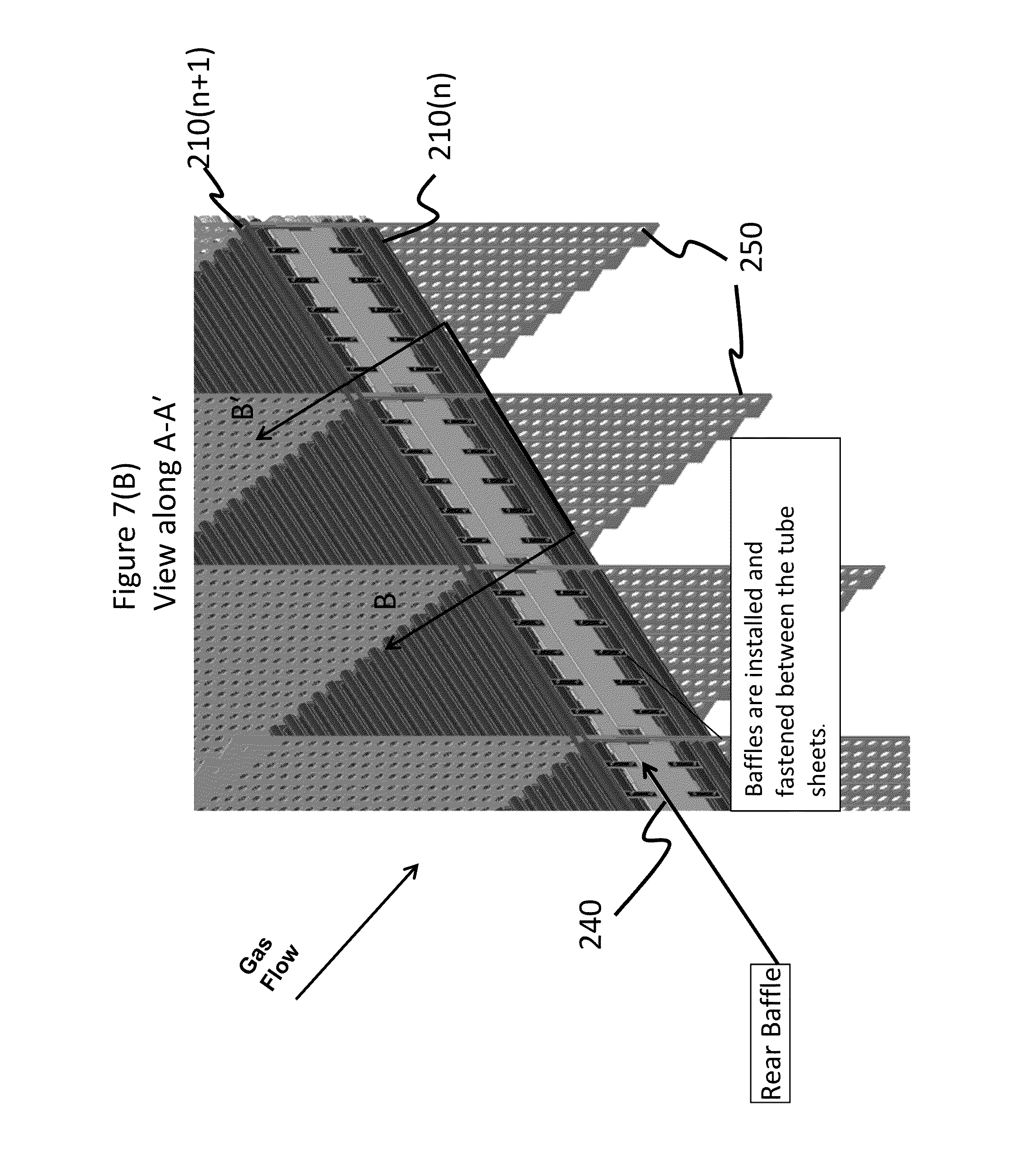
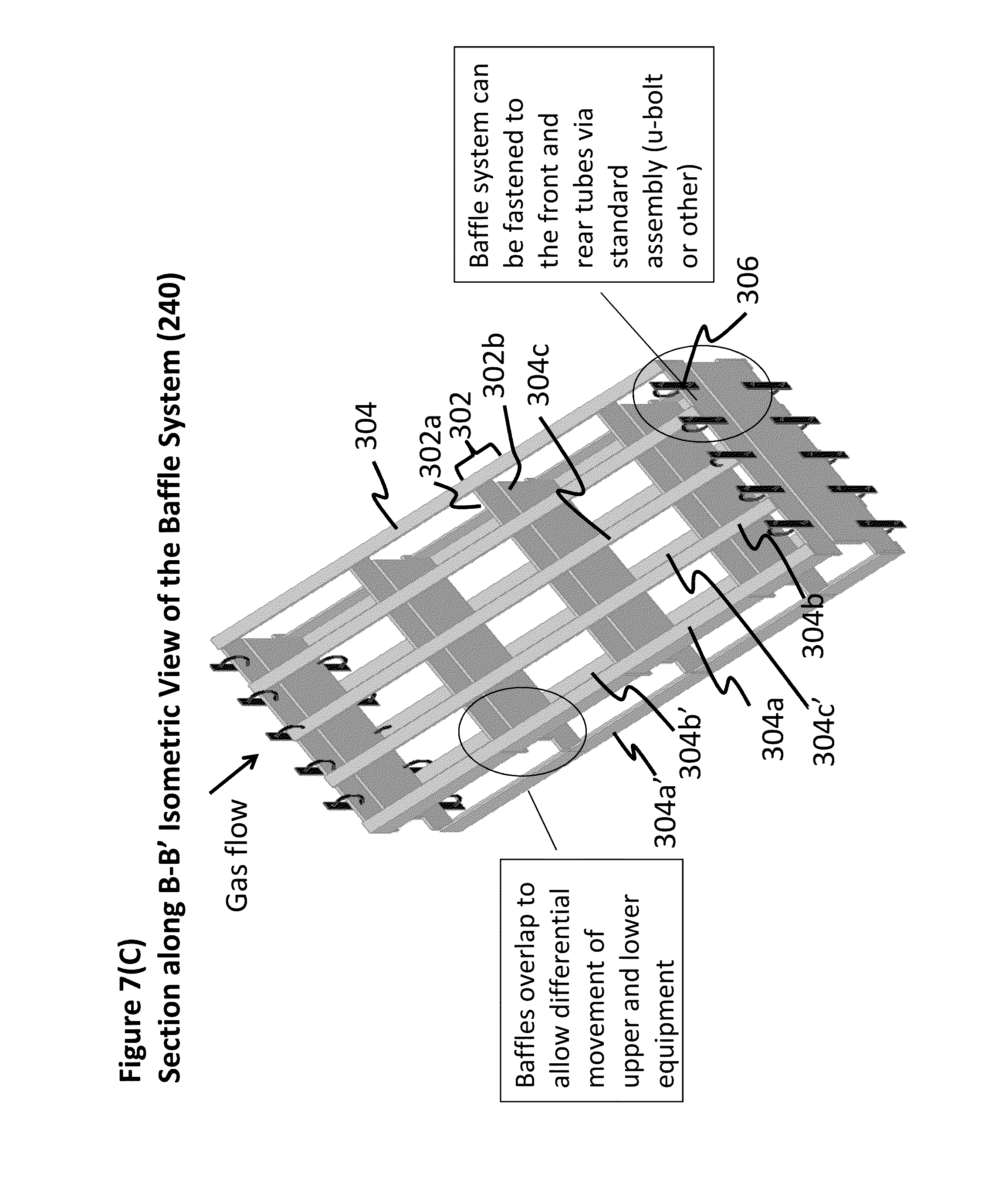
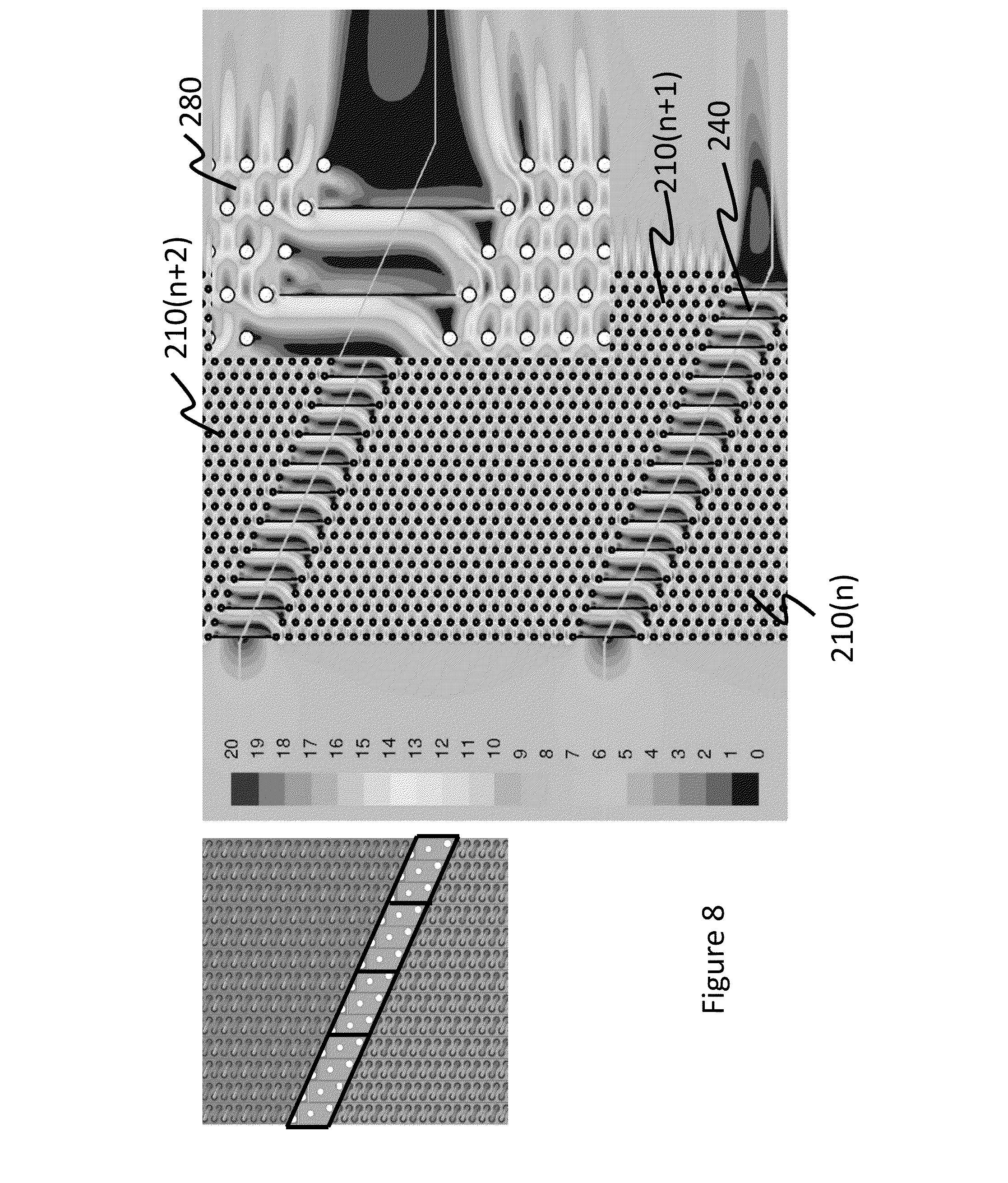
This disclosure claims priority to U.S. Provisional Application No. 61/587,332 filed Jan. 17, 2012, U.S. Provisional Application No. 61/587,230 filed Jan. 17, 2012, U.S. Provisional Application No. 61/587,428 filed Jan. 17, 2012, U.S. Provisional Application No. 61/587,359 filed Jan. 17, 2012, and U.S. Provisional Application No. 61/587,402 filed Jan. 17, 2012, the entire contents of which are all hereby incorporated by reference. The present disclosure relates generally to a heat recovery steam generator (HRSG), and more particularly, to a baffle for controlling flow in an HRSG having horizontal and/or inclined tubes for heat exchange. A heat recovery steam generator (HRSG) is an energy recovery heat exchanger that recovers heat from a hot gas stream. It produces steam that can be used in a process (cogeneration) or used to drive a steam turbine (combined cycle). Heat recovery steam generators generally comprise four major components—the economizer, the evaporator, the superheater and the water preheater. In particular, natural circulation HRSG's contain an evaporator heating surface, a drum, as well as piping to facilitate an appropriate circulation rate in the evaporator tubes. A once-through HRSG replaces the natural circulation components with the once-through evaporator and in doing so offers in-roads to higher plant efficiency and furthermore assists in prolonging the HRSG lifetime in the absence of a thick walled drum. An example of a once through evaporator heat recovery steam generator (HRSG) 100 is shown in the Due to design considerations, it is often the case that thermal head limitations use an additional heating loop in order to achieve superheated steam at the outlet. Often times, additional provisions are needed to remix water/steam bubbles prior to re-entry into the second heating loop, leading to additional design considerations. In addition, there exists a gas-side temperature imbalance downstream of the heating surface as a direct result of the vertically arranged parallel tubes. These additional design considerations utilize additional engineering design and manufacturing, both of which are expensive. These additional features also necessitate periodic maintenance, which reduces time for the productive functioning of the plant and therefore result in losses in productivity. It is therefore desirable to overcome these drawbacks. In addition, when a number of vertical tube sections (having vertical tubes) are placed next to one another, a substantial portion of the hot gases pass through the gaps between adjacent vertical sections without contacting the tube surfaces. This results in a loss of heat. It is therefore desirable to minimize the loss of heat due to the unrestricted flow of hot gases through open spaces between evaporator sections. Disclosed herein is a once-through evaporator comprising an inlet manifold; one or more inlet headers in fluid communication with the inlet manifold; one or more tube stacks, where each tube stack comprises one or more inclined evaporator tubes; the one or more tube stacks being in fluid communication with the one or more inlet headers; where the inclined tubes are inclined at an angle of less than 90 degrees or greater than 90 degrees to a vertical; one or more outlet headers in fluid communication with one or more tube stacks; and an outlet manifold in fluid communication with the one or more outlet headers; and a baffle system comprising a plurality of baffles; the baffle system being disposed adjacent to a tube stack so that the baffle system contacts a tube. Disclosed herein too is a method comprising discharging a working fluid through a once-through evaporator; where the once-through evaporator comprises an inlet manifold; one or more inlet headers in fluid communication with the inlet manifold; one or more tube stacks, where each tube stack comprises one or more inclined evaporator tubes; the one or more tube stacks being in fluid communication with the one or more inlet headers; where the inclined tubes are inclined at an angle of less than 90 degrees or greater than 90 degrees to a vertical; one or more outlet headers in fluid communication with one or more tube stacks; and an outlet manifold in fluid communication with the one or more outlet headers; and a baffle system comprising a plurality of baffles; the baffle system being disposed adjacent to a tube stack so that the baffle system contacts a tube; discharging a hot gas through the once-through evaporator; and transferring heat from the hot gas to the working fluid. Referring now to the Figures, which are exemplary embodiments, and wherein the like elements are numbered alike: Disclosed herein is a heat recovery steam generator (HRSG) that comprises a plurality of heat exchanger sections (hereinafter tube stacks) whose tubes are arranged to be “non-vertical”. The tube stacks have a baffle disposed between them. The baffle redirects the hot gases into the tube stacks. This facilitates improved heat transfer from the hot gases to a working fluid that travels in the tube stacks. By non-vertical, it is implied the tubes are inclined at an angle to a vertical. By “inclined”, it is implied that the individual tubes are inclined at an angle less than 90 degrees or greater than 90 degrees to a vertical line drawn across a tube. In one embodiment, the tubes can be horizontal in a first direction and inclined in a second direction that is perpendicular to the first direction. These angular variations in the tube along with the angle of inclination are shown in the The section (or plurality of sections) containing the horizontal tubes is also termed a “once-through evaporator”, because when operating in subcritical conditions, the working fluid (e.g., water, ammonia, or the like) is converted into vapor gradually during a single passage through the section from an inlet header to an outlet header. Likewise, for supercritical operation, the supercritical working fluid is heated to a higher temperature during a single passage through the section from the inlet header to the outlet header. The once-through evaporator (hereinafter “evaporator”) comprises parallel tubes that are disposed non-vertically in at least one direction that is perpendicular to the direction of flow of heated gases emanating from a gas turbine, furnace or boiler. The As can be seen in the The hot gases from a source (e.g., a furnace or boiler) (not shown) travel perpendicular to the direction of the flow of the working fluid in the tubes 210. The hot gases flow into the plane of the paper or out of the plane of the paper in the As seen in the The terms ‘n” is an integer value, while “n′” can be an integer value or a fractional value. n′ can thus be a fractional value such as ½, ⅓, and the like. Thus for example, there can therefore be one or more fractional inlet headers, tube stacks or outlet headers. In other words, there can be one or more inlet headers and outlet headers whose size is a fraction of the other inlet headers and/or outlet headers. Similarly there can be tube stacks that contain a fractional value of the number of tubes that are contained in the other stack. It is to be noted that the valves and control systems having the reference numeral n′ do not actually exist in fractional form, but may be downsized if desired to accommodate the smaller volumes that are handled by the fractional evaporator sections. In one embodiment, the once-through evaporator can comprise 2 or more inlet headers in fluid communication with 2 or more tube stacks which are in fluid communication with 2 or more outlet headers. In another embodiment, the once-through evaporator can comprise 5 or more inlet headers in fluid communication with 5 or more tube stacks which are in fluid communication with 5 or more outlet headers. In yet another embodiment, the once-through evaporator can comprise 10 or more inlet headers in fluid communication with 10 or more tube stacks which are in fluid communication with 10 or more outlet headers. There is no limitation to the number of tube stacks, inlet headers and outlet headers that are in fluid communication with each other and with the inlet manifold and the outlet manifold. Each tube stack is sometimes termed a zone. The Disposed on an upper surface of the once-through evaporator are rods 306 that contact the plates 250. Each rod 306 supports the plate and the plates hang (i.e., they are suspended) from the rod 306. The plates 250 (as detailed above) are locked in position using clevis plates. The plates 250 also support and hold in position the respective tube stacks 210( Since each rod 306 holds or supports a plate 250, the number of rods 306 are therefore equal to the number of the plates 250. In one embodiment, the entire once-through evaporator is supported and held-up by the rods 306 that contact the horizontal rods 304. In one embodiment, the rods 306 can be tie-rods that contact each of the parallel horizontal rods 304 and support the entire weight of the tube stacks. The weight of the once-through evaporator is therefore supported by the rods 306. Each section is mounted onto the respective plates and the respective plates are then held together by tie rods 300 at the periphery of the entire tube stack. A number of vertical plates support these horizontal heat exchangers. These plates are designed as the structural support for the module and provide support to the tubes to limit deflection. The horizontal heat exchangers are shop assembled into modules and shipped to site. The plates of the horizontal heat exchangers are connected to each other in the field. The tubes in each tube stack are serpentine as shown in the The Similarly, if a poorly designed distributive element were to be placed in the passage, non-uniform flow distribution would occur in the tube stacks. In one embodiment, depicted in the The The baffle system 240 is also provided with clips 306 by which they can be fastened to the lowest tube of the upper stack 210( Details of the baffle system 240 are shown in the As seen in the In another embodiment, the baffles can comprise a single plate or a plurality of plates that are perforated (not shown). These baffles may have a rod, or ribs or bars to reinforce the baffles. The perforation allows for deflection of the hot gases to the tube stacks either above, below or above and below the baffle system. The rods, ribs or reinforcing bars can be on the upstream side or the downstream side of the individual baffles. In one embodiment, the rods are welded to the plurality of baffles 302. In another embodiment, the rods can be attached to the plurality of baffles 302 by hinges (not shown). This latter arrangement permits the baffles to be angled with respect to the rods. By moving the rods 304 The plurality of baffles 302 disposed between the rods can vary depending upon the size of the tube stack. In an exemplary embodiment, there are at least 3 sets of baffles (parallel plates) 302, specifically at least 5 sets of plates, and more specifically at least 6 sets of plates per baffle system 240. In one embodiment, the baffles 302 are equidistantly spaced along the length of the rods. In another embodiment, the baffles 302 are not equidistantly spaced along the length of the rods. The angles between the baffles 302 and the rods 304 In one embodiment, the angle of inclination of the baffles may be changed by an actuator (not shown) that is in operative communication with a computer and a sensor (or a plurality of sensors) that is disposed in the once-through evaporator. The actuator can be activated by the reading from the sensor (e.g., a temperature sensor), a load requirement (such as electrical output), and the like. The entire feedback loop comprising the computer, the sensor and the actuator can be automated. When the baffle system 240 is placed in position in the passage 239 between the tube stacks, the hot gases are uniformly distributed into the tube stack as shown in the It is to be noted that this application is being co-filed with Patent Applications having Alstom docket numbers W11/122-1, W12/001-0, W11/123-1, W12/093-0, W11/120-1, W12/110-0 and W11/121-0, the entire contents of which are all incorporated by reference herein. Maximum Continuous Load” denotes the rated full load conditions of the power plant. “Once-through evaporator section” of the boiler used to convert water to steam at various percentages of maximum continuous load (MCR). “Approximately Horizontal Tube” is a tube horizontally orientated in nature. An “Inclined Tube” is a tube in neither a horizontal position or in a vertical position, but disposed at an angle therebetween relative to the inlet header and the outlet header as shown. It will be understood that, although the terms “first,” “second,” “third” etc. may be used herein to describe various elements, components, regions, layers and/or sections, these elements, components, regions, layers and/or sections should not be limited by these terms. These terms are only used to distinguish one element, component, region, layer or section from another element, component, region, layer or section. Thus, “a first element,” “component,” “region,” “layer” or “section” discussed below could be termed a second element, component, region, layer or section without departing from the teachings herein. The terminology used herein is for the purpose of describing particular embodiments only and is not intended to be limiting. As used herein, singular forms like “a,” or “an” and “the” are intended to include the plural forms as well, unless the context clearly indicates otherwise. It will be further understood that the terms “comprises” and/or “comprising,” or “includes” and/or “including” when used in this specification, specify the presence of stated features, regions, integers, steps, operations, elements, and/or components, but do not preclude the presence or addition of one or more other features, regions, integers, steps, operations, elements, components, and/or groups thereof. Furthermore, relative terms, such as “lower” or “bottom” and “upper” or “top,” may be used herein to describe one element's relationship to another elements as illustrated in the Figures. It will be understood that relative terms are intended to encompass different orientations of the device in addition to the orientation depicted in the Figures. For example, if the device in one of the figures is turned over, elements described as being on the “lower” side of other elements would then be oriented on “upper” sides of the other elements. The exemplary term “lower,” can therefore, encompasses both an orientation of “lower” and “upper,” depending on the particular orientation of the figure. Similarly, if the device in one of the figures is turned over, elements described as “below” or “beneath” other elements would then be oriented “above” the other elements. The exemplary terms “below” or “beneath” can, therefore, encompass both an orientation of above and below. Unless otherwise defined, all terms (including technical and scientific terms) used herein have the same meaning as commonly understood by one of ordinary skill in the art to which this disclosure belongs. It will be further understood that terms, such as those defined in commonly used dictionaries, should be interpreted as having a meaning that is consistent with their meaning in the context of the relevant art and the present disclosure, and will not be interpreted in an idealized or overly formal sense unless expressly so defined herein. Exemplary embodiments are described herein with reference to cross section illustrations that are schematic illustrations of idealized embodiments. As such, variations from the shapes of the illustrations as a result, for example, of manufacturing techniques and/or tolerances, are to be expected. Thus, embodiments described herein should not be construed as limited to the particular shapes of regions as illustrated herein but are to include deviations in shapes that result, for example, from manufacturing. For example, a region illustrated or described as flat may, typically, have rough and/or nonlinear features. Moreover, sharp angles that are illustrated may be rounded. Thus, the regions illustrated in the figures are schematic in nature and their shapes are not intended to illustrate the precise shape of a region and are not intended to limit the scope of the present claims. The term and/or is used herein to mean both “and” as well as “or”. For example, “A and/or B” is construed to mean A, B or A and B. The transition term “comprising” is inclusive of the transition terms “consisting essentially of” and “consisting of” and can be interchanged for “comprising”. While the invention has been described with reference to various exemplary embodiments, it will be understood by those skilled in the art that various changes may be made and equivalents may be substituted for elements thereof without departing from the scope of the invention. In addition, many modifications may be made to adapt a particular situation or material to the teachings of the invention without departing from the essential scope thereof Therefore, it is intended that the invention not be limited to the particular embodiment disclosed as the best mode contemplated for carrying out this invention, but that the invention will include all embodiments falling within the scope of the appended claims. Disclosed herein is a once-through evaporator comprising an inlet manifold; one or more inlet headers in fluid communication with the inlet manifold; one or more tube stacks, where each tube stack comprises one or more inclined evaporator tubes; the one or more tube stacks being in fluid communication with the one or more inlet headers; where the inclined tubes are inclined at an angle of less than 90 degrees or greater than 90 degrees to a vertical; one or more outlet headers in fluid communication with one or more tube stacks; and an outlet manifold in fluid communication with the one or more outlet headers; and a baffle system comprising a plurality of baffles; the baffle system being disposed adjacent to a tube stack so that the baffle system contacts a tube. 1. A once-through evaporator comprising:
an inlet manifold; one or more inlet headers in fluid communication with the inlet manifold; one or more tube stacks, where each tube stack comprises one or more inclined evaporator tubes; the one or more tube stacks being in fluid communication with the one or more inlet headers; where the inclined tubes are inclined at an angle of less than 90 degrees or greater than 90 degrees to a vertical; one or more outlet headers in fluid communication with one or more tube stacks; and an outlet manifold in fluid communication with the one or more outlet headers; and a baffle system comprising a plurality of baffles; the baffle system being disposed adjacent to a tube stack so that the baffle system contacts a tube. 2. The once-through evaporator of 3. The once-through evaporator of 4. The once-through evaporator of 5. The once-through evaporator of where the respective contact occurs via a clip or a u-bolt. 6. The once-through evaporator of 7. The once-through evaporator of 8. The once-through evaporator of 9. The once-through evaporator of 10. The once-through evaporator of 11. The once-through evaporator of 12. The once-through evaporator of 13. The once-through evaporator of 14. A method comprising:
discharging a working fluid through a once-through evaporator; where the once-through evaporator comprises: an inlet manifold; one or more inlet headers in fluid communication with the inlet manifold; one or more tube stacks, where each tube stack comprises one or more inclined evaporator tubes; the one or more tube stacks being in fluid communication with the one or more inlet headers; where the inclined tubes are inclined at an angle of less than 90 degrees or greater than 90 degrees to a vertical; one or more outlet headers in fluid communication with one or more tube stacks; and an outlet manifold in fluid communication with the one or more outlet headers; and a baffle system comprising a plurality of baffles; the baffle system being disposed adjacent to a tube stack so that the baffle system contacts a tube; discharging a hot gas from a furnace or boiler through the once-through evaporator; and transferring heat from the hot gas to the working fluid. 15. The method of CROSS-REFERENCE TO RELATED APPLICATIONS
TECHNICAL FIELD
BACKGROUND
SUMMARY
BRIEF DESCRIPTION OF THE DRAWINGS
DETAILED DESCRIPTION