PERSONAL PROTECTION SYSTEM WITH A FAN THAT INCLUDES CURVED BLADES
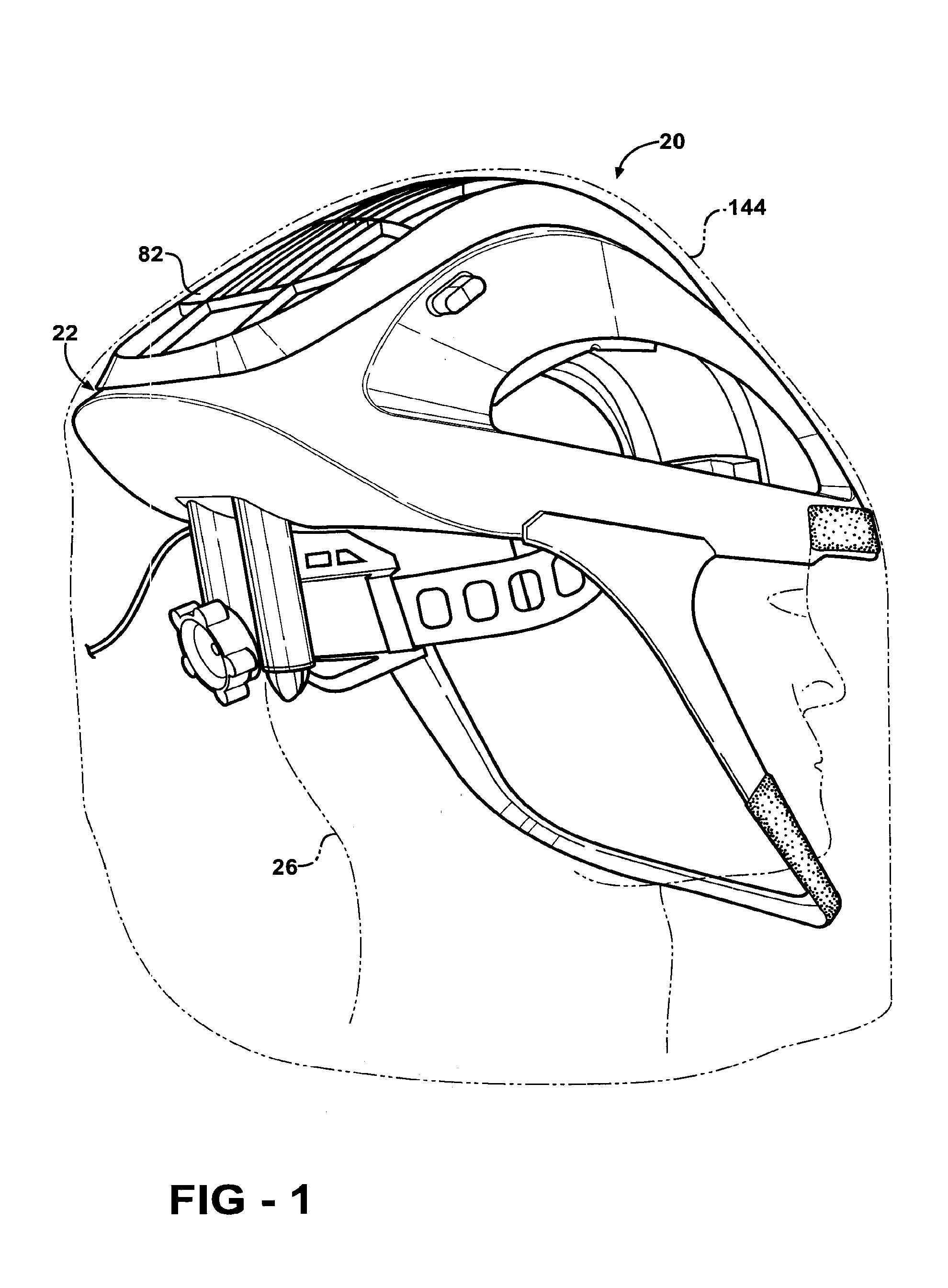
This application is a divisional of U.S. patent application Ser. No. 12/834,566 filed 12 Jul. 2010 now U.S. Pat. No. 8,407,818. Application Ser. No. 12/834,566 is a divisional of U.S. patent application Ser. No. 11/277,424 filed 24 Mar. 2006 now U.S. Pat. No. 7,752,682. Application Ser. No. 11/277,424 claims the benefit of provisional application Ser. No. 60/664,900 filed 24 Mar. 2005. The contents of the above-listed applications are incorporated by reference. The subject invention generally relates to a personal protection system mountable to a user for distributing air to the user. The personal protection system is utilized in the medical profession during surgical procedures. The subject invention more specifically relates to a helmet assembly and gown for use in the personal protection system. Personal Protection systems and helmet assemblies utilized in personal protection systems are known in the art. AS indicated above, personal protection systems are worn by users throughout the medical profession, such as surgeons, during medical procedures Conventional personal protection systems and helmet assemblies are deficient for one reason or another. For example, U.S. Pat. No. 6,990,691 to Klotz et al. (the '691 patent) discloses a helmet assembly that draws air in with a fan assembly and distributes the air to front and rear air exits. However, when the helmet assembly is worn by the user, the air exit is disposed such that the air is vented near the middle of the back of the head of the user. Thus, the air cannot be directed toward the neck of the user, where most surgeons desire the air's cooling presence. Other deficiencies of prior art personal protection systems are with the fan assembly. For instance, the shape of the blades of the fan, which rotate to draw in air, do not provide for the most efficient and quietest flow of air possible. This causes excessive power consumption, which leads to premature drain of battery packs, and excessive noise, which can be distracting for a surgeon performing delicate operations. Furthermore, the prior art helmet assemblies tend to transfer vibrations caused by the rotation of the fan to the user, as well as being noisy in general. The vibrations, as well as the noise, can be distracting to the surgeon, who obviously needs to focus his efforts at the complex task at hand. Yet another deficiency of the '691 patent concerns the multiple removable layers disposed on the face shield. The '691 patent is silent as to sterility of the multiple removable layers. However, sterilization concerns are of an utmost importance for any product involved in the surgical process. For the above mentioned reasons, it is desirous to provide a personal protection system which provides more control over air flow to the neck of the user and which provides more efficient and quieter means for moving the flow of air. Furthermore, it is desirous to provide a personal protection system which noise and vibrations, which can be distracting to the surgeon, are kept to a minimum. Moreover, it is desirous to provide a face shield with removable layers that is sterilized in an efficient manner. In a first aspect of the invention, a personal protection unit is disclosed. The personal protection unit includes a support structure for suspending a hood over the head of an individual. A fan module is attached to the support structure, with the fan module receiving air and discharging air. A duct is connected to the support structure and has an opening positioned to receive the air discharged from the fan module. The duct is shaped to have a rear air exit. The duct is arranged relative to the fan module so that only a fraction of the air discharged from the fan module enters the duct. The duct extends from the support structure and the rear air exit is positioned so that air is discharged from the rear air exit directly onto the neck of the individual. By the duct extending from the support structure and discharging air directly on to the neck, the comfort of the individual (e.g., a surgeon) is increased, allowing the individual to focus on the task he or she is performing (e.g., surgery). In a second aspect of the invention, the personal protection unit includes the support structure for suspending the hood over the head of the individual. The personal protection unit includes a fan for circulating air. A motor is attached to the support structure and is connected to the fan for actuating the fan. An elastomeric, vibration dampening member holds the motor to the support structure. The vibration dampening member helps to reduce transmission of noise and/or vibrations generated by the fan and/or motor to the user. Reduction of noise and/or vibrations will decrease distractions to the individual. A third aspect of the subject invention provides the personal protection system with the hood formed of flexible sterilizable material, a portion of which is filter material, and shaped to be worn over the head. A transparent face shield is attached to the hood. The personal protection system includes a support structure for suspending the hood over the head. A fan is attached to the support structure for circulating air through the hood. A plurality of individually removable layers of sterile transparent material are disposed over the face shield. A fourth aspect of the invention provides a method of assembling a sterilized hood assembly having a transparent face shield. The method includes the step of providing a hood formed from sterilizable flexible material, a portion of the material being filter material. A transparent face shield assembly is attached to the hood where the shield assembly includes a face shield. The method further includes the step of sterilizing the hood and face shield assembly using a sterilization process that does not adversely affect the filter material. The transparent shield assembly further includes a plurality of removable transparent layers disposed over the face shield. Sterilizing the face shield and removable layers together as a whole provides for a more effective assembly process by negating the possibility of introducing contaminants during subsequent assembly operations. Other advantages of the present invention will be readily appreciated, as the same becomes better understood by reference to the following detailed description when considered in connection with the accompanying drawings wherein: Referring to the Figures, wherein like numerals indicate corresponding parts throughout the several views, a personal protection system or personal protection unit is generally shown at 20. The personal protection system 20 is mountable to a user (i.e., an individual) for distributing air to the user. The personal protection system 20 of the present invention is adapted from the personal protection systems disclosed in U.S. Pat. Nos. 6,481,019 to Diaz et al. (the '019 patent) and 6,973,677 to Diaz et al. (the '677 patent), which are hereby incorporated by reference. In the preferred embodiment, as shown in The personal protection system 20 of the subject invention may be described hereafter in terms of the helmet assembly 22 of the preferred embodiment. However, this should not be construed as limiting the personal protection system 20 to the helmet assembly embodiment. Referring to The air flow channel 34 channels air about the head 24 of the user. The inner and outer shell portions 30, 32 may form the air flow channel 34 from a two-sheet thermoforming process which improves the structural strength of the shell 28. More specifically, each of the inner and outer shell portions 30, 32 include an outer periphery, and in the two-sheet thermoforming process, the inner and outer shell portions 30, 32 are pinched together at their outer peripheries. The air flow channel 34 is subsequently thermoformed between the pinched outer peripheries. The helmet assembly 22 also includes a facial section 36 extending from the shell 28 to define a facial opening 38. The facial section 36 of the helmet assembly 22 is a chin bar 40. Preferably, the chin bar 40 is flexible and is formed of plastic. The chin bar 40 may also be formed of a polypropylene component. The flexibility of the chin bar 40 protects the user's face and also absorbs impact when the user contacts an external object with the helmet assembly 22. Referring now to Referring again to Referring to Referring to Referring now to Referring back to The scroll housing 50 of the preferred embodiment may include an inclined surface 78 (or cutoff) along the outer wall 70 at one or more of the air outlets 76. The inclined surface 78 in the preferred embodiment is inclined relative to a rotational axis of the fan 46 and motor 48. The inclined surface 78 moves air more efficiently through the air outlet 76. In effect, a blade-pass frequency at each air outlet 76 employing the inclined surface 78 is altered such that at least two blades 64 pass the air outlet 76 simultaneously. The outer wall 70 is preferably wrapped outwardly away from the fan 46 at the outlet with the inclined surface 78 such that a flange portion 80 of the outer wall 70 defines the inclined surface 78. Preferably, the outer wall 70 is rounded at the flange portion 80 to provide a smooth transition to the air outlet 76. This reduces noise from the air flowing through the air outlet 76. Referring again to The air inlet 74 of the scroll housing 50 is in direct communication with a hole 86 formed within the outer shell portion 32 of the shell 28 for drawing air into the scroll housing 50. In alternative embodiments of the present invention, an external structure, not shown in the Figures, can be mounted external to the helmet assembly 22 to establish the air inlet 74 of the scroll housing 50 for drawing air into the scroll housing 50. The hole 86 formed in the outer shell portion 32 may be circular in shape. The diameter of the hole 86 may be sized in relation to a diameter of the fan 46 such that only a portion of the fan 46 diameter is exposed when viewed through the air inlet 74 in the outer shell portion 32. This ratio of air inlet 74 diameter to fan 46 diameter may be from 1:2 to 1:1, more preferably, from 1:1.5 to 1:1.1. Referring to In operation, the motor 48 rotates the fan 46 to draw air into the air inlet 74 of the scroll housing 50 through the intake grid 82 and the air inlet 74 in the outer shell portion 32 and distributes air out of the scroll housing 50 through the air outlet 76 or outlets and into the air flow channel 34 where the air is distributed about the head 24 of the user. Cutoffs (in some embodiments, inclined cutoffs as previously described) cut the air as the fan 46 moves the air within the scroll housing 50. More specifically, as shown in the Figures, the present invention incorporates several air flow cutoffs in the scroll housing 50 to cut the air. A power supply is incorporated in the present invention to power the motor 48 to rotate the fan 46 via the motor 48 shaft. Preferably, the power supply is a rechargeable DC battery. Also preferred, the power supply is disposed within, i.e., integrated into, the helmet assembly 22. In such a case, the power supply is referred to as an integral power supply. Alternatively, the power supply can be mounted to the body 26 of the user (not shown). The power supply powers the motor 48 through pulse width modulation (PWM) which will be discussed further below. The design of the scroll housing 50 provides more efficient movement of air with less power being required from the power supply overall. Furthermore, in addition to such reduced power requirements, the scroll housing 50 provides that sufficient air flow can be maintained with overall less air velocity. This results in a quieter helmet assembly 22. With respect to the at least two air outlets 76, the outer wall 70 of the scroll housing 50 is partitioned to define the air outlets 76. In the preferred embodiment of the present invention having the at least two air outlets 76, it is to be understood that the present invention is not limited to at least two air outlets 76. That is, the present invention may include, for example, three or four air outlets 76. The air outlets 76 provide a complete balance of air as the air is distributed from the scroll housing 50 about the head 24 of the user. To accomplish this, the helmet assembly 22 includes at least two helmet air exits 90, 92 in fluid communication with the air flow channel 34. The air outlets 76 are in fluid communication with the at least two helmet air exits 90, 92 to distribute the air from the air outlets 76, which is in the air flow channel 34, toward the head 24 of the user. In the preferred embodiment of the present invention where the helmet assembly 22 includes the at least two helmet air exits 90, 92 it is not critical that the scroll housing 50 include at least two air outlets 76. To the contrary, the scroll housing 50, in these embodiments, may only have at least one air outlet 76. Furthermore, the helmet assembly 22 may also have only one air exit. In an alternative embodiment, at least one air bleed valve (not shown) may be incorporated in the scroll housing 50 to influence the amount, or the volume, of air flowing into the air flow channel 34 from each of the air outlets 76. This is shown in the '019 patent to Diaz et al., which is hereby incorporated by reference. In the preferred embodiment, as best shown in Still referring to The rear air exits 92 are incorporated in a nozzle assembly 98 (also referred to as a duct 98 or a duct assembly 98). Referring to Referring to The nozzle 100 is preferably formed of ABS, while the nozzle tips 102 are preferably formed of LEXAN® polycarbonate. Of course, the nozzle 100 and nozzle tips 102 may be formed of other suitable materials known to those skilled in the art. Referring to Referring to A method of maintaining a constant volume of air flowing into the helmet assembly 22 during or throughout the entire use of the personal protection system 20 by the user is provided by the present invention. The method includes the step of selectively activating and deactivating the power supply as detailed in the '677 patent, which is hereby incorporated by reference. Referring again to Viscoelastic foam pads (not shown) may be applied to the helmet assembly 22 at various locations to provide a comfortable barrier between the user and the helmet assembly 22. In the preferred embodiment, the materials used to form the helmet assembly 22, particularly the materials used to form the shell 28, scroll housing 50, and the fan 46, were selected based on their sound-dampening characteristics. The stiffness of these materials was selected to reduce vibration and change the frequency of transmitted sound to more appeasing frequencies. Referring back to Referring now to Referring to However, in an alternative embodiment, the removable layers 150 may be sterilized with Ethylene Oxide (EtO) gas. In this embodiment, the removable layers 150 must be breathable for effective EtO gas sterilization. In one embodiment, the removable layers 150 are attached directly to the face shield 146 using a self-adhering method of attachment such as static forces, transparent adhesive, and the like. As shown, the removable layers 150 may include peel tabs 152 that the user or an assistant can grab to peel-away the removable layers 150 from the face shield 146. The tabs 152 can be positioned at any portion of the removable layers 150 such as at the top for “peel down” removal, at the bottom for “peel up” removal, or at the side for “peel across” removal. Furthermore, each of the removable layers 150 may have multiple tabs 152. The removable layers 150 preferably include anti-reflective and/or anti-refractive coatings to improve vision by reducing multiple images. In one embodiment, the removable layers 150 are formed from a 1 to 5 mil clear urethane film. In further embodiments, the removable layers 150 are formed of polyester, e.g., Mylar®, or other gamma radiation stable materials to reduce or eliminate air layers 150 between adjacent removable layers 150. In an alternative embodiment, the removable layers 150 are thin and semi-rigid or rigid and conform to the shape of the face shield 146, while still minimizing the air gap between adjacent removable layers 150. The removable layers 150 may be formed as a semi-rigid or rigid film. In this embodiment, the removable layers 150 may be attached at a periphery of the face shield 146 in a non-continuous manner such as by adhesive, tape, spot-welding, static cling attachment, or other conventional methods of attachment. This allows EtO gas to penetrate the periphery for terminal sterilization between the removable layers 150. In this embodiment, the removable layers 150 may be manufactured in a flat configuration and then wrapped to conform to the curvature of the face shield 146, which minimizes the air gaps between the removable layers 150 to reduce unwanted images when looking through the face shield 146 and the removable layers 150. The removable layers 150 in this embodiment may also include anti-reflective and/or anti-refractive coatings to improve vision and may also include tabs 152 to remove the removable layers 150. In further embodiments, the removable layers 150, whether thin and flexible or thin and semi-rigid or rigid, may be polarized using a polarized coating. The removable layers 150 may also include magnification coatings to improve the user's view. Magnification may be carried out solely by the removable layers 150, or in alternative embodiments, magnification may be carried out by a combination of the removable layers 150 and the face shield 146. In even further embodiments, magnification is carried out solely by the face shield 146. In addition, the removable layers 150 may provide UV protection by using UV inhibiting films or adhesives. The face shield 146 may be packaged with multiple removable layers 150 ready for removal from the face shield 146 during use. However, in some instances it may be beneficial to provide a user with greater flexibility in selecting the types of removable layers 150 to be used, e.g., thin and flexible or thin and semi-rigid or rigid, or to provide the user the option of selecting whether the removable layers 150 will be used at all. To this end, each removable layer 150 (flexible, semi-rigid, or rigid) is packaged separately from the face shield 146 incorporated into the hood 144 or gown. As a result, the user can choose, which, and how many, of the removable layers 150 to attach to the face shield 146 prior to use. Alternatively, a removable layer 150 (flexible, semi-rigid, or rigid) may be separately packaged and formed with anti-reflective, anti-refractive, and/or magnification coatings to improve image quality for the user. In this instance, the coatings may work with complementary coatings on the face shield 146 to improve the image quality for the user, or the removable layer 150 may be the sole source of these coatings. In the event that the removable layers 150 are separately packaged, they will also be separately sterilized using either EtO gas sterilization, or preferably gamma radiation sterilization. When gamma radiation sterilization is used, the air layers 150 between adjacent removable layers 150 can be reduced or eliminated, which improves image quality through the removable layers 150. The use of gamma stable materials to form the removable layers 150 also improves optical clarity. The present invention preferably includes a positioning and supporting system for assisting a single user in self-gowning as the user maintains sterility. This system is fully described in the '019 patent to Diaz et al., hereby incorporated by reference. The present invention may also include a visual positioning system as disclosed in the '019 patent to Diaz et al., hereby incorporated by reference. Obviously, many modifications and variations of the present invention are possible in light of the above teachings. The invention may be practiced otherwise than as specifically described within the scope of the appended claims. In addition, the reference numerals in the claims are merely for convenience and are not to be read in any way as limiting. A personal protection system with a hood and a helmet that is worn under the hood. Internal to the helmet is a fan that draws air into the hood. The fan has blades that are curved along their longitudinal axes. 1-20. (canceled) 21. A personal protection system for fitting over a head, said system comprising:
a head band shaped to be fitted around the head; a shell connected to said head band so as to be located above the head, the shell having an inlet opening; a motor mounted to said shell that is disposed within said shell; a fan mounted to said motor for rotation by said motor, said fan including: a base plate having a center and an outer perimeter; and a plurality of arcuately spaced apart blades that extend upwardly from a surface of said base plate, said blades having longitudinal axis that extend from ends of said blades adjacent the center of said base plate to ends of said blades adjacent the outer perimeter of said base plate, wherein said blade are further shaped so as to be curved such that the longitudinal axes of said blades are curved and being tapered such that, extending distally from the ends of said blades adjacent the center of said base plate, the cross sectional thickness of said blade decreases and wherein said motor and said fan are collectively positioned so that when said motor actuates said fan, said fan draws air in through the shell inlet opening; at least one nozzle connected to said shell for receiving air discharged by said fan, said nozzle positioned to direct air downwardly towards the head or neck; a hood that is disposed over said head band, said shell and said nozzle so as to extend over the head and neck, said hood having a transparent face shield that is positioned to be forward of a front of the head; and a fastening assembly connected to at least one of said shell or said hood for releasably holding said hood to said shell. 22. The personal protection system of said fan is further formed to have a hub that protrudes outwardly from said base plate, said hub being centered on the center of said base plate and said blades are located on said base plate so as to be spaced radially outwardly from said hub; and said motor is disposed in said hub and has a rotating shaft that is mounted to said hub. 23. The personal protection system of said blades extend upwardly from said base plate a first distance; said fan is further formed to have a hub that extends upwardly from said base plate said hub being centered on the center of said base plate and extending upwardly from said base plate a second distance, the second distance being less than the first distance and said blades are located on said base plate so as to be spaced radially outwardly from said hub; and said motor is disposed in said hub and has a rotating shaft that is mounted to said hub. 24. The personal protection system of 25. The personal protection system of 26. The personal protection system of said fan base plate is shaped so that the outer perimeter of said base plate is circular; and at least one said fan blade is shaped to have: a top surface that extends longitudinally along said blade, a bottom surface opposite the top surface that extends longitudinally along said blade; adjacent the center of said fan base; a leading surface that extends between the blade top surface and the blade bottom surface, the leading surface having a convex profile; and a trailing surface located opposite the leading surface, the trailing surface extending between the top surface and the bottom surface, wherein said blade is further shaped so that the trailing surface extends upwardly from the outer perimeter of said fan base plate and extends around an arc that is defined by the outer perimeter of said base plate. 27. The personnel protection system of said fan and said motor are connected to a motor mount disposed in said shell; at least one motor cushion is disposed between said motor mount and said shell; and fasteners hold said motor mount to said shell so as to hold said motor mount against said at least one motor cushion. 28. The personal protection system of 29. The personnel protection system of 30. A personal protection system for fitting over a head, said system comprising:
a head band shaped to be fitted around the head; a shell connected to said head band so as to be located above the head, the shell having an inlet opening; a fan disposed in said shell, said fan including: a base plate having a center and an outer perimeter; a hub integral with said base plate that extends upwardly from the center of said hub; and a plurality of arcuately spaced apart blades that extend upwardly from said base plate, said blades having leading surfaces that are spaced radially outwardly away from said hub the leading surfaces being convex in shape, longitudinal axes that extend from the leading surfaces toward the outer perimeter of said base plate, top surfaces that extend longitudinally away from the leading surfaces, bottom surfaces opposite the top surfaces that extend longitudinally away from the leading surfaces wherein said blade are further shaped so that the top and bottom surfaces are curved and being tapered such that extending longitudinally from the leading surfaces that cross sectional distance across the blades from the top surfaces to the bottom surfaces decreases; and wherein said blade extends upwardly from said base plate so as to extend above said hub; a motor mounted to said shell so as to be disposed in said fan hub, said motor having a drive shaft that is connected to said fan hub to rotate said fan, wherein said fan and said motor are position so that the rotation of said fan draws air into the shell through the shell inlet opening; at least one nozzle connected to said shell for receiving air discharged by said fan and that is further shaped and positioned to direct air downwardly towards the head or neck; a hood that is disposed over said head band, said shell and said nozzle so as to extend over the head and neck, said hood having a transparent face shield that is positioned to be forward of a front of the head; and a fastening assembly connected to at least one of said shell or said hood for releasably holding said hood to said shell. 31. The personal protection system of 32. The personal protection system of said fan base plate is shaped so that the outer perimeter of said base plate is circular; and at least one said fan blade is further shaped to have: a trailing surface located opposite the leading surface, the trailing surface extending between the top surface and the bottom surface of the said fan blade with which said trailing surface is associated and wherein said blade is further shaped so that the trailing surface extends upwardly from the outer perimeter of said fan base plate and extends around an arc that is defined by the outer perimeter of said base plate. 33. The personnel protection system of said fan and said motor are connected to a motor mount disposed in said shell; at least one motor cushion is disposed between said motor mount and said shell; and fasteners hold said motor mount to said shell so as to hold said motor mount against said at least one motor cushion. 34. The personal protection system of 35. The personnel protection system of 36. A personal protection system for fitting over a head, said system comprising:
a head band shaped to be fitted around the head; a shell connected to said head band so as to be located above the head, the shell having an inlet opening; a motor mounted to said shell that is disposed within said shell; a fan mounted to said motor for rotation by said motor, said fan including: a circularly shaped base plate having a center and an outer perimeter; and a plurality of arcuately spaced apart blades that extend upwardly from a surface of said base plate, a plurality of said blades each having: a longitudinal axis that extends radially outwardly from an end of said blade plate adjacent the center of said base plate; a top surface that extends longitudinally along said blade; a bottom surface opposite the top surface that extends longitudinally along said blade, wherein said blade is curved so that the longitudinal axis and top and bottom surfaces of said blade are curved; a leading surface adjacent the center of said base plate that extends between the blade top and bottom surfaces, the leading surface having a convex shape; and a trailing surface opposite the leading surface that extends between the top and bottom surfaces of said blade and that extends upwardly from the outer perimeter of said base plate and that extends around an arc that is defined by the outer perimeter of said base plate and wherein said motor and said fan are collectively positioned so that when said motor actuates said fan, said fan draws air in through the shell inlet opening; at least one nozzle connected to said shell for receiving air discharged by said fan, said nozzle positioned to direct air downwardly towards the head or neck; a hood that is disposed over said head band, said shell and said nozzle so as to extend over the head and neck, said hood having a transparent face shield that is positioned to be forward of a front of the head; and a fastening assembly connected to at least one of said shell or said hood for releasably holding said hood to said shell.REFERENCES TO RELATED APPLICATIONS
FIELD OF THE INVENTION
BACKGROUND OF THE INVENTION
SUMMARY OF THE INVENTION AND ADVANTAGES
BRIEF DESCRIPTION OF THE DRAWINGS
DETAILED DESCRIPTION OF THE INVENTION