IMAGE FORMING APPARATUS
1. Field of the Invention The present invention relates to an image forming apparatus and a process cartridge used for the image forming apparatus. Herein, the image forming apparatus is an apparatus that forms an image on a recording medium by using an electrophotographic method. In addition, examples of the image forming apparatus include copying machines, printers (e.g., laser beam printers, LED printers), facsimile machines, and word processors that use the electrophotographic method. 2. Description of the Related Art In an electrophotographic image forming apparatus (hereinbelow, also simply referred to as an image forming apparatus), an electrophotographic photosensitive member (hereinbelow, also simply referred to as a photosensitive member) as an image bearing member is uniformly charged. Then, the charged photosensitive member is selectively exposed to light according to image information, and an electrostatic image (electrostatic latent image) is formed on the photosensitive member. The electrostatic image is developed (visualized) as a toner image (developer image) with developer. Then, the toner image is transferred to a recording medium. Thereafter, the toner image is fixed and recorded to the recording medium by adding heat and pressure to the recording medium to which the toner image is transferred. In the image forming apparatus, in order to form an image, the photosensitive member of a process cartridge mounted on the image forming apparatus main body and a process unit (process member) acting on the photosensitive member need to be rotated. The photosensitive member and process unit are subjected to electrostatic or physical actions respectively by elements such as other process units. Therefore, a specific torque is needed to rotate the photosensitive member or the process unit. The torque required for the rotation may vary due to the influence of the rotation period of the photosensitive member or the process unit. However, during image formation, if fluctuation of torque occurs, the rotational circumferential speed of the photosensitive member or the developer bearing member serving as the process unit may vary to cause image defect such as density unevenness or pitch unevenness. Therefore, Japanese Patent Application Laid-open No. 05-080651 discusses a technique in which a drive path of an agitation member, which is susceptible to a load fluctuation caused by agglutination of developer, is provided in a different route from the drive path of the photosensitive member or the developer bearing member. However, with the above-described conventional configuration, if the developer bearing member and the agitation member are driven at a same time during image formation, a common drive source mounted in the image forming apparatus main body needs to provide a drive torque of the agitation member in addition to a drive torque of the developer bearing member. Therefore, in order to reduce the influence of the variation of the rotation period of the developing unit as described above, a power source that can supply larger power is required, resulting in increase in cost or power consumption. This applies to a case where drive sources are provided independently for driving the developer bearing member and the agitation member. In addition, not limited to the developer bearing member, the same problem may occur when the photosensitive member (image bearing member) and the agitation member are driven at a same time. The present invention is directed to an image forming apparatus and a process cartridge capable of performing stable image formation without being influenced by the driving load fluctuation of an agitation member while preventing an increase in cost and power consumption of a power source. According to an aspect of the present invention, an image forming apparatus configured to form an image on a recording medium, includes a developer container configured to store developer, an image bearing member configured to be rotated and on which a latent image is formed, a developer bearing member configured to bear developer and to be rotated to develop the latent image, an agitation member configured to be rotated to agitate the developer stored in the developer container, and a control unit configured to control the rotations of the image bearing member, the developer bearing member, and the agitation member so as to rotate the agitation member while the image bearing member is not rotated. Further features of the present invention will become apparent from the following description of exemplary embodiments with reference to the attached drawings. An image forming apparatus and a process cartridge according to an exemplary embodiment are described in more detail below with reference to the drawings. First, an overall configuration of an image forming apparatus according to a first exemplary embodiment is described. In the present exemplary embodiment, a full color image forming apparatus with four attachable/detachable process cartridges is exemplified as an image forming apparatus. However, the number of process cartridges mounted on the image forming apparatus is not limited thereto, and can be determined as needed. For example, in a case of an image forming apparatus that forms monochrome images, the number of process cartridges to be mounted thereon is one. In addition, in the present exemplary embodiment, a printer is exemplified as an example of an image forming apparatus. However, it is not limited thereto. For example, the present invention can be applied to other image forming apparatuses such as copying machines, facsimile machines, or multi-function peripherals including these functions. In the present exemplary embodiment, a side of the image forming apparatus 1 with an open/close door 3 is referred to as a front side, and the opposite side of the front side thereof is referred to as a back side. Further, the right side of the image forming apparatus 1 viewed from the front side is referred to as a driving side, and the left side thereof is referred to as a non-driving side. In the apparatus main body 2, four process cartridges of a first process cartridge PY, a second process cartridge PM, a third process cartridge PC, and a fourth process cartridge PK are disposed in substantially a horizontal direction. The first to fourth process cartridges PY, PM, PC, and PK include a similar electrophotographic process mechanism, but toner colors used as a developer are different from each other. In the present exemplary embodiment, when a process cartridge for each color is not to be discriminated, it is simply referred to as a “process cartridge P”. To the process cartridge P, the rotation drive force is transmitted from a drive output unit (described below) of the apparatus main body 2. Further, to the process cartridge P, a bias voltage (e.g., charging bias, developing bias) is applied from a bias power source (not illustrated) of the apparatus main body 2. As illustrated in In the present exemplary embodiment, a charging roller 5, which is a roller type charging member, is used as a charging unit, a cleaning blade 7 is used as a cleaning unit, and a developing roller 6, which is a developer bearing member, is used as a developing unit (developing member). More specific configuration of the process cartridge P will be described below. The first process cartridge PY stores yellow (Y) toner in a developer container 29 and forms a yellow toner image on the surface of the photosensitive drum 4. The second process cartridge PM stores magenta (M) toner in the developer container 29 and forms a magenta toner image on the surface of the photosensitive drum 4. The third the process cartridge PC stores cyan (C) toner in the developer container 29 and forms a cyan toner image on the surface of the photosensitive drum 4. The fourth the process cartridge PK stores black (K) toner in the developer container 29 and forms a black toner image on the surface of the photosensitive drum 4. Above the first to fourth process cartridges PY, PM, PC, and PK in Below the first to fourth process cartridges PY, PM, PC, and PK in The peripheral surface of the photosensitive drums 4 of the first to fourth process cartridges PY, PM, PC, and PK are brought into contact with the surface of the intermediate transfer belt 12. In the present exemplary embodiment, in a state where the process cartridge P is mounted on the apparatus main body 2, the bottom surface of the photosensitive drum 4 is brought into contact with the upper surface of the intermediate transfer belt 12. The contact portion is a primary transfer portion N1. On the inner peripheral surface side of the intermediate transfer belt 12, primary transfer rollers 16 are disposed respectively facing photosensitive drums 4 of the first to fourth process cartridges PY, PM, PC, and PK. The primary transfer roller 16 presses the intermediate transfer belt 12 to the photosensitive drum 4 to form a primary transfer portion N1. The primary transfer portion N1 is a contact portion of the intermediate transfer belt 12 and the photosensitive drum 4. A secondary transfer roller 17 (i.e., secondary transfer unit) is brought into contact with the drive roller 13 via the intermediate transfer belt 12. The contact portion of the intermediate transfer belt 12 and the secondary transfer roller 17 is a secondary transfer portion N2. Below the intermediate transfer belt unit 11 in Upper left portion within the apparatus main body 2 in Next, the image forming operation is described using a case of forming a full color image as an example. Each of the photosensitive drums 4 of the first to fourth process cartridges PY, PM, PC, and PK is rotated in an arrow D direction in Further, the laser scanner unit LB is driven. In synchronization with the driving of the laser scanner unit LB, in the first to fourth process cartridges PY, PM, PC, and PK, the surface of the photosensitive drum 4 is uniformly charged by a charging roller 5 in a predetermined polarity and potential. Then, the surface of the photosensitive drum 4 is subjected to scanning and exposure of the laser beam L of the laser scanner unit LB according to an image signal of each color. With this operation, an electrostatic image (electrostatic latent image or latent image) is formed on the surface of each photosensitive drum according to an image signal of each color. The electrostatic image formed on the photosensitive drum 4 is developed by the developing roller 6 that is rotated at a predetermined speed. The developing roller 6 can bear developer on its surface, and can form a developer image (toner image) corresponding to the electrostatic image on the surface of the photosensitive drum 4 by supplying developer to the photosensitive drum 4. In the present exemplary embodiment, the developing roller 6 contacts the photosensitive drum 4, and is rotated so that the moving direction of developing roller 6 at the contact portion with the photosensitive drum 4 becomes forward direction with respect to the moving direction of the photosensitive drum 4 (arrow E direction in Through the above-described electrophotographic image forming process operation, on the photosensitive drum 4 of the first process cartridge PY, a yellow toner image corresponding to a yellow component of a full color image is formed. Then, the toner image is primary transferred onto the intermediate transfer belt 12. Similarly, on the photosensitive drum 4 of the second process cartridge PM, a magenta toner image corresponding to a magenta component of the full color image is formed. Then, the toner image is superimposed on the yellow toner image which has been already primary transferred on the intermediate transfer belt 12. Similarly, on the photosensitive drum 4 of the third process cartridge PC, a cyan color toner image corresponding to a cyan component of the full color image is formed. Then, the toner image is primary transferred to superimpose on the yellow and magenta toner images which have been already transferred on the intermediate transfer belt 12. Similarly, on the photosensitive drum 4 of the fourth cartridge PK, a black toner image is formed corresponding to a black component of the full color image. Then, the toner image is primary transferred to superimpose on the yellow, magenta, and cyan toner images which have been already transferred on the intermediate transfer belt 12. In this way, a full color (i.e., four colors) unfixed toner image of yellow, magenta, cyan, and black is formed on the intermediate transfer belt 12. On the other hand, in the feeding unit 18, a recording medium S is separated and fed one by one at a predetermined control timing. The recording medium S is introduced to the secondary transfer portion N2, which is a contact portion of the secondary transfer roller 17 and the intermediate transfer belt 12 at a predetermined control timing. Through this operation, in the process of the recording medium S being conveyed to the secondary transfer portion N2, the toner image with the four color images superimposed on the intermediate transfer belt 12 is collectively and sequentially secondary transferred on the surface of the recording medium S. As illustrated in As illustrated in The photosensitive drum 4 is rotatably supported by the driving side cover member 24 and the non-driving side cover member 25 at both end portions in the rotation axis direction thereof. Further, a drum drive output unit (output side coupling) 51 illustrated in The charging roller 5 is rotatably supported by charging roller bearings 27 of the cleaning container 26 at both end portions in the rotation axis direction thereof. The charging roller 5 contacts the surface of the photosensitive drum 4 to be rotated according to the rotation of the photosensitive drum 4. Further, the charging bias is supplied to the charging roller 5 from a charging bias power source (not illustrated) serving as a charging voltage apply unit of the apparatus main body 2. Thus, the surface of the photosensitive drum 4 is charged. At that time, in order to charge the surface of the photosensitive drum 4 uniformly, both end portions of the charging roller 5 in the rotation axis direction thereof is pressurized by a pressurizing spring 28 against the surface of the photosensitive drum 4. The cleaning blade 7 serving as a cleaning unit is fixed to the cleaning container 26, and the elastic rubber portion of the end portion (free end portion) thereof is brought into contact with the peripheral surface of the photosensitive drum 4. In the present exemplary embodiment, the elastic rubber portion thereof is brought into contact with the photosensitive drum 4 in the counter direction of the rotational direction of the photosensitive drum 4 (arrow D direction illustrated in As illustrated in The developing roller 6, which is a developer bearing member serving as a developing unit, and a supply roller 31 serving as a developer supply member are arranged in the opening of the developer container 29. Both end portions in the rotation axis direction of the developing roller 6 and the supply roller 31 are rotatably supported with the driving side bearing 36 and the non-driving side bearing 37, respectively attached to both side surfaces of the developer container 29. In the present exemplary embodiment, the rotation axis direction of the developing roller 6 and the rotation axis direction of the supply roller 31 are substantially in parallel. Further, in the present exemplary embodiment, the rotation axis directions of the developing roller 6 and the supply roller 31 are substantially parallel with the rotation axis direction of the photosensitive drum 4. Further, at the driving side end portions of a core member 6 The developing drive input gear 40 includes a developing drive coupling 40 In the present exemplary embodiment, the developing roller 6 and the supply roller 31 are rotated so that the moving directions thereof become opposite to each other at each contact portion (arrows E and F directions in The developing blade 30 as a developer regulation member is fixed to the developer container 29, and the end portion (free end portion) thereof is brought into contact with the peripheral surface of the developing roller 6. In the present exemplary embodiment, the developing blade 30 is brought into contact with the peripheral surface of the developing roller 6 in a counter direction of the rotational direction (arrow E direction in The developing unit 9 is constantly urged by a pressurizing spring (not illustrated) serving as an urging means to a direction (arrow G direction in During image formation, the supply roller 31 and the developing roller 6 are rotated while contacting and pressing each other, toner in the toner container 29 The agitation shaft 32, the agitation sheet 33, the agitation shaft gear 34, and the agitation drive gear 35 in the developing unit 9 will be described in detail below. As illustrated in At the driving side surface of the developer container 29, the agitation drive gear 35 is rotatably supported and engaged with the agitation shaft gear 34. The agitation drive gear 35 is provided with an agitation drive coupling 35 In this way, toner is agitated to accelerate circulation of the toner in the vertical direction. Thus, the deviation of the toner amount in a longitudinal direction is improved. Accordingly, the toner state supplied to the developing roller 6 and the supply roller 31 can be uniform, and thus stable image forming can be achieved. In addition, in the present exemplary embodiment, in a state where the process cartridge P is mounted on the apparatus main body 2, the toner container 29 Next, the operation of the agitation blade 60 will be described. In the present exemplary embodiment, the agitation blade 60 is generally rotated when the developing roller 6 and the photosensitive drum 4 are not rotated. On the other hand, the agitation blade 60 is not rotated when the developing roller 6 and the photosensitive drum 4 are rotated. Herein, the control method according to the present exemplary embodiment will be described. The CPU 101 performs control of the image formation operation sequence according to the control programs stored in the ROM 102, and also performs control of the operation sequence of the agitation blade 60. The control of the operation sequence of the agitation blade 60 will be described below in more detail. According to the present exemplary embodiment, the CPU 101 controls drive/stop and the driving speed of each of the drum drive motor M1, the developing drive motor M2, and the agitation drive motor M3. As described above, the drive force from the drum drive motor M1 is transmitted to the photosensitive drum 4 by connecting the drum drive output unit 51 (i.e., drive output unit of the apparatus main body 2 side) and the drum drive coupling 4 Next, the operation sequences during the image formation and the toner agitation will be described. In the present exemplary embodiment, during image formation, the photosensitive drum 4 and the developing drive input gear 40 are rotated by the drive force obtained from the drum drive motor M1 and the developing drive motor M2 of the apparatus main body 2. At that time, as illustrated in As a result, the rotation speeds of the photosensitive drum 4 and the developing roller 6 are not varied caused by the drive torque of the agitation blade 60. Therefore, even if a power source that cannot supply large power is used for the image forming apparatus 1, stable image formation can be performed without density unevenness and pitch unevenness. On the other hand, when toner in the toner container 29 In the present exemplary embodiment, toner in the toner container 29 When the image forming signal (i.e., image formation start instruction) is input to the image forming apparatus 1, the CPU 101 starts driving the drum drive motor M1, and starts rotating the photosensitive drum 4 (t1). At substantially the same timing, the CPU 101 starts driving the developing drive motor M2, and starts rotating the developing roller 6 and the supply roller 31 (t1). Then, the laser scanner unit LB starts to form an electrostatic image (t2). After the laser scanner unit LB finishes forming the electrostatic image (t3), each step of developing, transferring (primary transfer and secondary transfer) (not illustrated), the CPU 101 stops the drum drive motor M1 and the developing drive motor M2. With this operation, the photosensitive drum 4, the developing roller 6, and the supply roller 31 stops to be rotated (t4). Thereafter, the CPU 101 starts driving the agitation drive motor M3, starts rotating the agitation blade 60 (t5), and during a predetermined period, toner in the toner container 29 Through such a sequence, the developing drive motor M2 for driving the developing roller 6 as a process unit, and the agitation drive motor M3 for driving the agitation blade 60 as an agitation member can be driven at different timings. Further, in the present exemplary embodiment, through the above described sequence, the drum drive motor M1 for driving the photosensitive drum 1, and the agitation drive motor M3 for driving the agitation blade 60 as an agitation member can be driven at different timings. Further, in the present exemplary embodiment, during the driving of the agitation drive motor M3, all the motors for driving the rotation members in the intermediate transfer belt unit 11, the feeding unit 18, and the fixing unit 21, are stopped. Therefore, the output power of the power source 200 of the apparatus main body 2 can be restrained. The power source 200 is used for driving the developing drive motor M2, the agitation drive motor M3, the drum drive motor M1, and drive motors for driving other rotation members. As a result, power consumption of the image forming apparatus 1 can be restrained, and increase in cost can be restrained, which is caused by using a large output power source. Further, since the operation can be achieved with a simple and easy sequence of switching the driving of motors, it does not bring about an increase in cost due to increase of sensors and actuators. As described above, the image forming apparatus 1 according to the present exemplary embodiment includes the developer container (toner container 29 As described above, according to the present exemplary embodiment, without increase in cost and power consumption of the power source, stable image formation can be achieved without influence of the drive load variation of the agitation blade 60. Next, a second exemplary embodiment of the present invention will be described. The basic configuration and the operation of the image forming apparatus according to the present exemplary embodiment are similar to those of the first exemplary embodiment. Therefore, components having the same or corresponding functions or configurations of the first exemplary embodiment are denoted the same symbols, and detailed descriptions thereof are omitted. In the first exemplary embodiment, the agitation blade 60 agitates toner in the toner container 29 In the present exemplary embodiment, when the image formation is repeatedly performed for a long time, a sequence is provided for driving the agitation blade 60 for a predetermined time period between the image formation operations according to the number of image formed sheets and the operation time (image formation time). Through this operation, the image defect caused by toner supply shortage can be prevented from being generated. The agitation blade 60 is driven during the image formation on a recording medium S and the next recording medium S, in continuous image formation. At that time, in the present exemplary embodiment, similar to the first exemplary embodiment, in the developing unit 9, toner is stored above the developing roller 6 and the supply roller 31. With this configuration, the weight of toner itself can be used for supplying toner to the developing roller 6 and the supply roller 31. Therefore, even when the image formation is repeated for a long time, since the supply shortage of toner rarely occurs, the driving time of the agitation blade 60 can be minimized. As a result, the power consumption due to the drive of the agitation blade 60 can be reduced. Further, the deterioration of the repetition speed of image formation can be prevented. When the image forming signal (i.e., image formation start instruction) is input to the image forming apparatus 1, the CPU 101 starts to drive the drum drive motor M1, and rotate the photosensitive drum 4 (t1). At substantially the same timing, the CPU 101 starts to drive the developing drive motor M2, and rotate the developing roller 6 and the supply roller 31 (t1). Then, the laser scanner unit LB starts to form an electrostatic image (t2). After the laser scanner unit LB finishes forming the electrostatic image (t3), and each step of developing, transferring (primary transfer and secondary transfer) (not illustrated), the CPU 101 stops the drum drive motor M1 and the developing drive motor M2. Through this operation, the photosensitive drum 4, the developing roller 6, and the supply roller 31 are caused to stop rotating (t4). Then, the CPU 101 starts to drive the agitation drive motor M3, rotate the agitation blade 60 (t5), and during a predetermined period, toner in the toner container 29 More specifically, when the number of the sheets of image formation or the image formation time of the job is larger than a predetermined number of sheets of image formation or longer than a predetermined image formation time, the CPU 101 performs the following control. Specifically, for each predetermined number of sheets of image formation or each predetermined image formation time, the CPU 101 repeats to drive the agitation blade 60 for a predetermined time (t9, t10, t11, and t12). Then, the job (a series of image forming operations for one or more recording media by one image forming start instruction) is completed. As described above, for each predetermined number of sheets of image formation or each operation time (predetermined image formation time, the CPU 101 drives the agitation blade 60 for a predetermined time. However, the sequence for driving the agitation blade 60 for a predetermined time according to the number of sheets of image formation or the operation time (image formation time) is not limited thereto. For example, as the number of sheets of image formation or the image formation time is increased, the frequency of driving the agitation blade 60 may be increased, or the predetermined time for driving the agitation blade 60 may be longer. In this way, in the present exemplary embodiment, the control unit once halts the image forming operation during the continuous image forming operation on a plurality of recording media, and performs operation of driving agitation member for a predetermined time. As described above, according to the present exemplary embodiment, even when image formation is repeated for a long time, since the supply shortage of toner rarely occurs, and the similar effect to that of the first exemplary embodiment can be obtained. The exemplary embodiment of the present invention has been described above. However, the present invention is not limited thereto. For example, in the exemplary embodiments described above, the drum drive motor M1, the developing drive motor M2, and the agitation drive motor M3 are separately provided. However, for example, with a configuration in which the driving force from one motor of the apparatus main body 2 may be switched to each of driving output units of the photosensitive drum 4, the developing roller 6, and the agitation blade 60. In this case also, the similar effect can be obtained. Then, during image formation, as illustrated in In the above-described exemplary embodiments, the drive forces from separate drive sources are transmitted to the photosensitive drum 4 and the developing roller 6, via separate drive input units. However, it is not limited thereto. The electrophotographic photosensitive member and the process unit may be connected for driving, and the drive force from a common drive source may be transmitted via a common drive input unit. Further, as desired, the agitation member may be driven when at least one of the photosensitive member and the process unit is not driven. With this configuration, depending on the configuration of the image forming apparatus, without increase in cost and power consumption, stable image formation can be performed without influence of variation of the drive load of the agitation member. Further, in the above-described exemplary embodiments, the process unit rotated and acting on the electrophotographic photosensitive member is the developing roller 6 as a developing unit. However, it is not limited thereto. For example, the process unit may be any process unit as long as it is rotated and can act on an electrophotographic photosensitive member. Such examples include a charging roller as a charging unit that can be rotated and charge the photosensitive drum 4, and a brush roller as a cleaning unit that can be rotated and remove transfer residual toner remaining on the photosensitive drum 4. Further, a plurality of process units can be included. As described above, the process cartridge may be integrally configured including at least an electrophotographic photosensitive member, a process unit, a developer container, and an agitation member, and may be attachable and detachable to and from the apparatus main body of the electrophotographic image forming apparatus. More specifically, the process cartridge includes a first drive input unit provided separately or commonly for receiving rotation drive forces from the apparatus main body to the electrophotographic photosensitive member and the process unit. Further, the process cartridge includes a second drive input unit for receiving a rotation drive force from the apparatus main body to the agitation member. The agitation member can be rotated when at least one of the electrophotographic photosensitive member and the process unit is not driven. In the above-described exemplary embodiments, the drum drive coupling 4 Hereinbelow, a configuration according to a third exemplary embodiment will be described with reference to In the present exemplary embodiment, as illustrated in However, if the agitation sheet 33 is formed longer, the following issues may occur. Specifically, when the agitation blade 60 is rotated, if the agitation sheet 33 touches the inner wall of the toner container 29 Accordingly, in the present exemplary embodiment, similar to the above-described first exemplary embodiment, the control unit 100 (see Further, in the present exemplary embodiment, similar to the first and second exemplary embodiments, power consumed when the agitation blade 60 is rotated (power consumption) can be reduced. Further, in the present exemplary embodiment, similar to the above-described exemplary embodiments, when the developing roller 6 is stopped, the supply roller 31 also is stopped. Therefore, when the agitation blade 60 is rotated, there is no rotating member in the process cartridge P. Therefore, the power consumption when the agitation blade 60 is rotated can be further reduced. Hereinbelow, referring to In the present exemplary embodiment, the agitation sheet 33 disposed in the toner container 29 In this configuration, the agitation sheet 33 lifts up toner in the vertical direction upward to convey the toner. The agitation sheet 33 is brought into contact with the partition wall 29 In the present exemplary embodiment, both the position of the holding unit 29 In the present exemplary embodiment, similar to the above-described first exemplary embodiment, the agitation blade 60 is rotated when the photosensitive drum 4 and the developing roller 6 are not rotated. In other words, while the photosensitive drum 4 and the developing roller 6 are not forming an image, the agitation blade 60 is rotated. In this way, toner is accumulated in the holding unit 29 If the image formation is continuously performed and the toner stored in the holding unit 29 In the present exemplary embodiment, the agitation blade 60 is rotated while the photosensitive drum 4 and the developing roller are not rotating, power necessary when the agitation blade 60 is rotated can be reduced. The feature of the present exemplary embodiment resides in that two states where the developing roller 6 contacts the photosensitive drum 4 and the developing roller 6 separates from the photosensitive drum 4 can be switched. More specifically, a cam 86 is in contact with the developing unit 9. The developing unit 9 is rotatable around a rotation center 9 In addition, the circles illustrated with dotted lines in The agitation shaft gear 34 is attached to the agitation shaft 32 to receive drive force for rotating the agitation blade 60 from the gear 85 The image forming apparatus 1 according to the present exemplary embodiment includes an interlocking mechanism for switching the agitation blade 60 and the developing roller 6 between the stop state and the rotation state, interlocking with the rotation of the cam 86. The interlocking mechanism includes above-described gears such as the gear 85 As illustrated in Next, as illustrated in In other words, the agitation blade 60 is rotatable only when the developing roller 6 and the photosensitive drum 4 are separated. On the other hand, the developing roller 6 and the photosensitive drum 4 are rotatable only when they are in contact with each other. Since all of the agitation blade 60, the developing roller 6, and the photosensitive drum 4 do not rotate together, power required to rotate each member can be small. A table illustrating contact/separation state of the developing roller 6 and the photosensitive drum 4 and rotation/stop state of each member is as follows. In addition, arrangements of the gears illustrated in the present exemplary embodiment are just an example and may be changed arbitrarily according to an embodiment. Further, the interlocking mechanism in the present exemplary embodiment is configured only by gears. More specifically, the gears 85 The interlocking mechanism according to the present exemplary embodiment switches between the rotation state and the stop state (i.e., the drive force is transmitted and not transmitted) of the three members of the developing roller 6, the photosensitive drum 4, and the agitation blade 60 according to the rotation of the cam 86. However, one member or two members of the three members may be switched. Alternatively, the interlocking mechanism may switch the rotation state of the supply roller 33 according to the rotation of the cam 86. For example, in this case, the interlocking mechanism may stop driving the supply roller 33 when the developing roller 6 and the photosensitive drum are separated, and may drive the supply roller 33 to rotate when the developing roller 6 and the photosensitive drum 4 are brought into contact with each other. At last, effects of exemplary embodiments are summarized as follows. It is possible to perform stable image formation without being influenced by variation of drive load of the agitation member while suppressing increase of the power source in cost and increase in power consumption. While the present invention has been described with reference to exemplary embodiments, it is to be understood that the invention is not limited to the disclosed exemplary embodiments. The scope of the following claims is to be accorded the broadest interpretation so as to encompass all such modifications and equivalent structures and functions. This application claims the benefit of Japanese Patent Application No. 2012-153651, filed Jul. 9, 2012, which is hereby incorporated by reference herein in its entirety. An image forming apparatus configured to form an image on a recording medium, includes a developer container configured to store developer, an image bearing member configured to be rotated and on which a latent image is formed, a developer bearing member configured to bear developer and to be rotated to develop the latent image, an agitation member configured to be rotated to agitate the developer stored in the developer container, and a control unit configured to control the rotations of the image bearing member, the developer bearing member, and the agitation member so as to rotate the agitation member while the image bearing member is not rotated. 1. An image forming apparatus configured to form an image on a recording medium, comprising:
a developer container configured to store developer; an image bearing member configured to be rotated and on which a latent image is formed; a developer bearing member configured to bear developer and to be rotated to develop the latent image; an agitation member configured to be rotated to agitate the developer stored in the developer container; and a control unit configured to control the rotations of the image bearing member, the developer bearing member, and the agitation member so as to rotate the agitation member while the image bearing member is not rotated. 2. The image forming apparatus according to 3. The image forming apparatus according to wherein the agitation member is configured, when rotated, to contact the supply roller. 4. The image forming apparatus according to wherein the control unit is configured to control rotations of the supply roller and the agitation member so as to rotate the agitation member while the supply roller is not rotated. 5. The image forming apparatus according to a contact/separation mechanism configured to switch between contact and separation of the developer bearing member with and from the image bearing member; an interlocking mechanism configured to switch, interlocking with the contact/separation mechanism, between a state where drive force is transmitted to the agitation member and developer bearing member and a state where the drive force is not transmitted to the agitation member and developer bearing member, and wherein when the contact/separation mechanism causes the developer bearing member to be brought into contact with the image bearing member, the interlocking mechanism causes the drive force to be transmitted to the developer bearing member, and not to be transmitted to the agitation member, wherein when the contact/separation mechanism separates the developer bearing member from the image bearing member, the interlocking mechanism causes the drive force not to be transmitted to the developer bearing member, and to be transmitted to the agitation member, and wherein the control unit is configured to control the rotation drive of the developer bearing member and the agitation member by controlling the contact/separation mechanism. 6. The image forming apparatus according to wherein the interlocking mechanism causes the drive force to be transmitted to the image bearing member when the developer bearing member is brought into contact with the image bearing member, and causes the drive force not to be transmitted to the image bearing member when the developer bearing member is separated from the image bearing member, and wherein the control unit is configured to control the contact/separation mechanism to control the rotation drive of the image bearing member. 7. The image forming apparatus according to 8. The image forming apparatus according to and the image forming apparatus further comprising a holding unit configured to hold the developer conveyed from the developer container by the agitation member, and wherein the developer container is disposed below a supply position of toner to the developer bearing member and the holding unit, in a vertical direction. 9. The image forming apparatus according to 10. The image forming apparatus according to 11. The image forming apparatus according to 12. The image forming apparatus according to BACKGROUND OF THE INVENTION
SUMMARY OF THE INVENTION
BRIEF DESCRIPTION OF THE DRAWINGS
DESCRIPTION OF THE EMBODIMENTS
1. Overall Configuration of Image Forming Apparatus
2. Image Forming Operation
3. Configuration of Process Cartridge
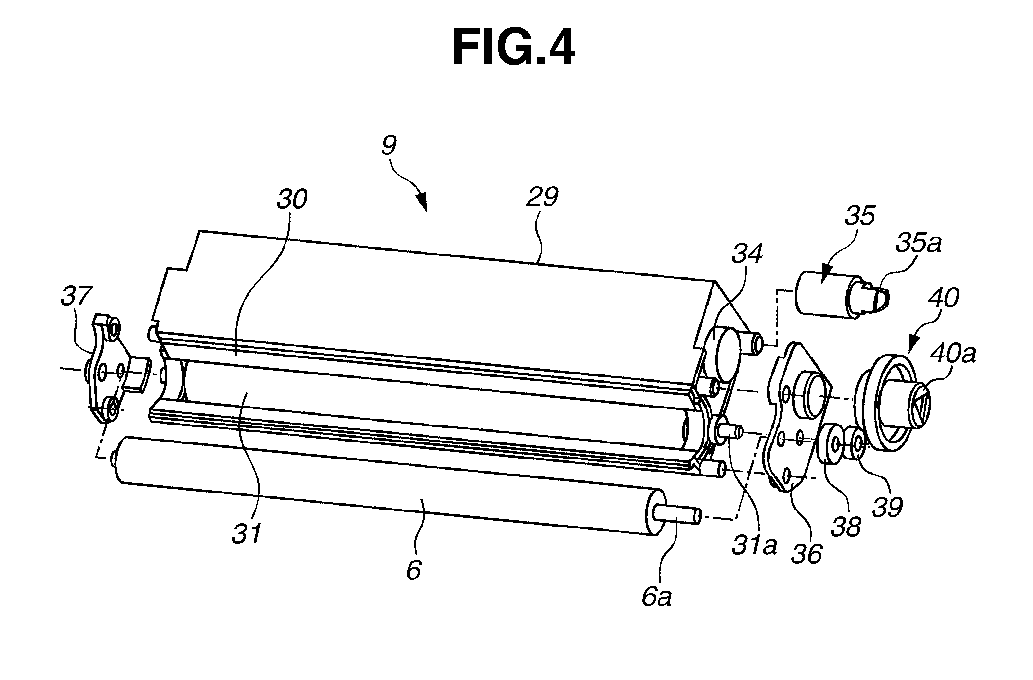
4. Configuration of Developing Unit
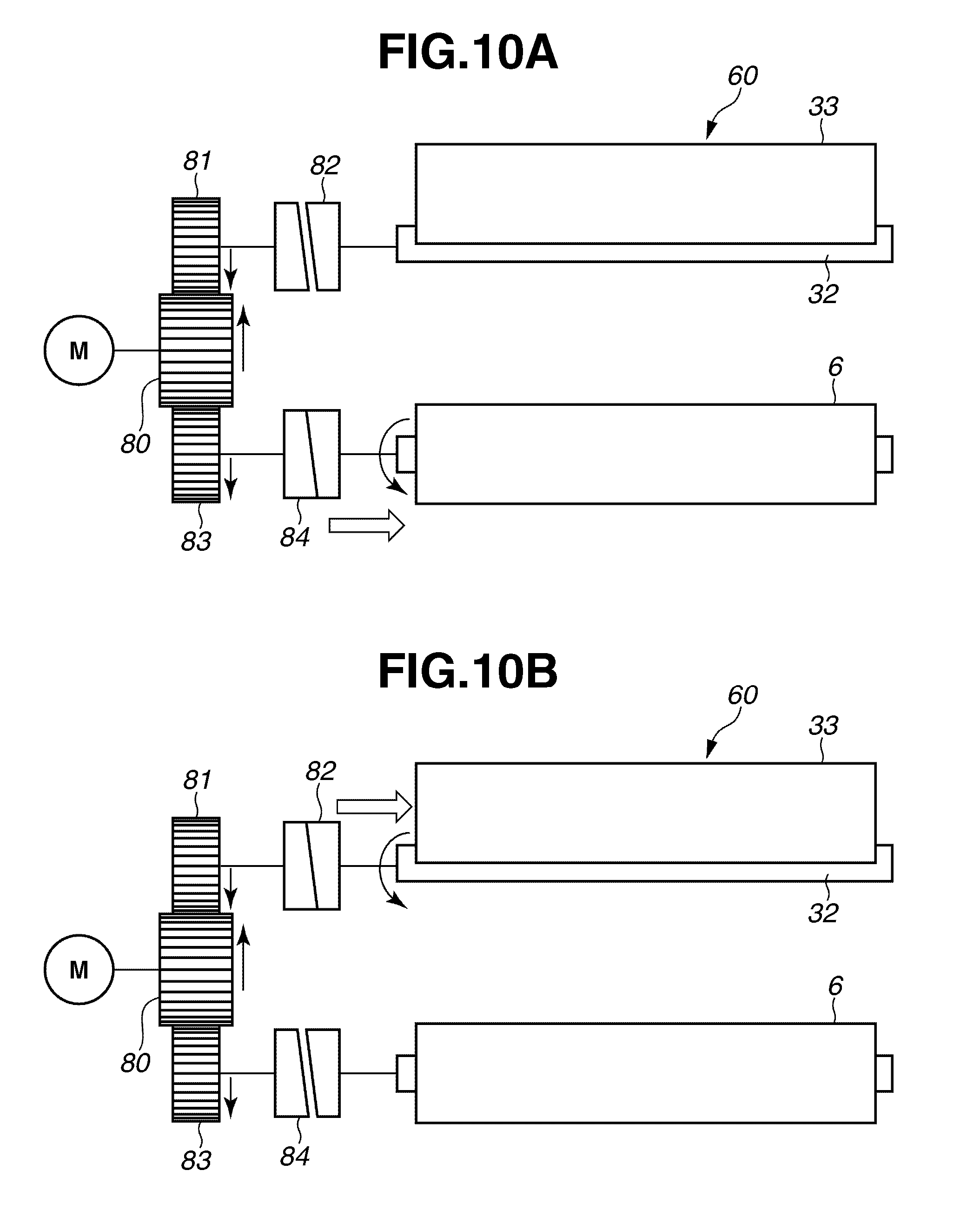
5. Configuration of Agitation Member
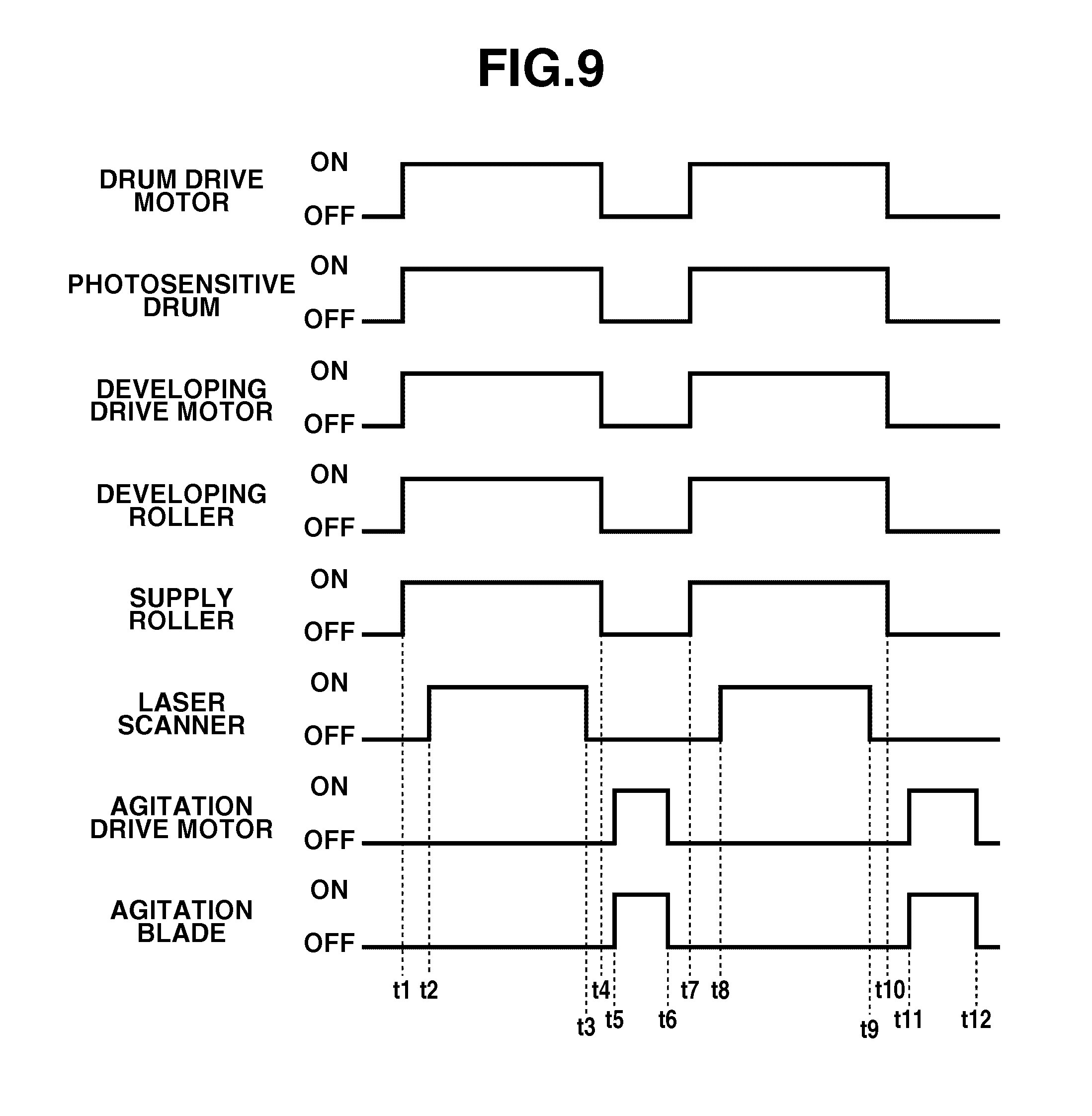
6. Operation of Agitation Blade
developing rotation rotation stop roller and photosensitive drum are in contact developing stop stop rotation roller and photosensitive drum are separated
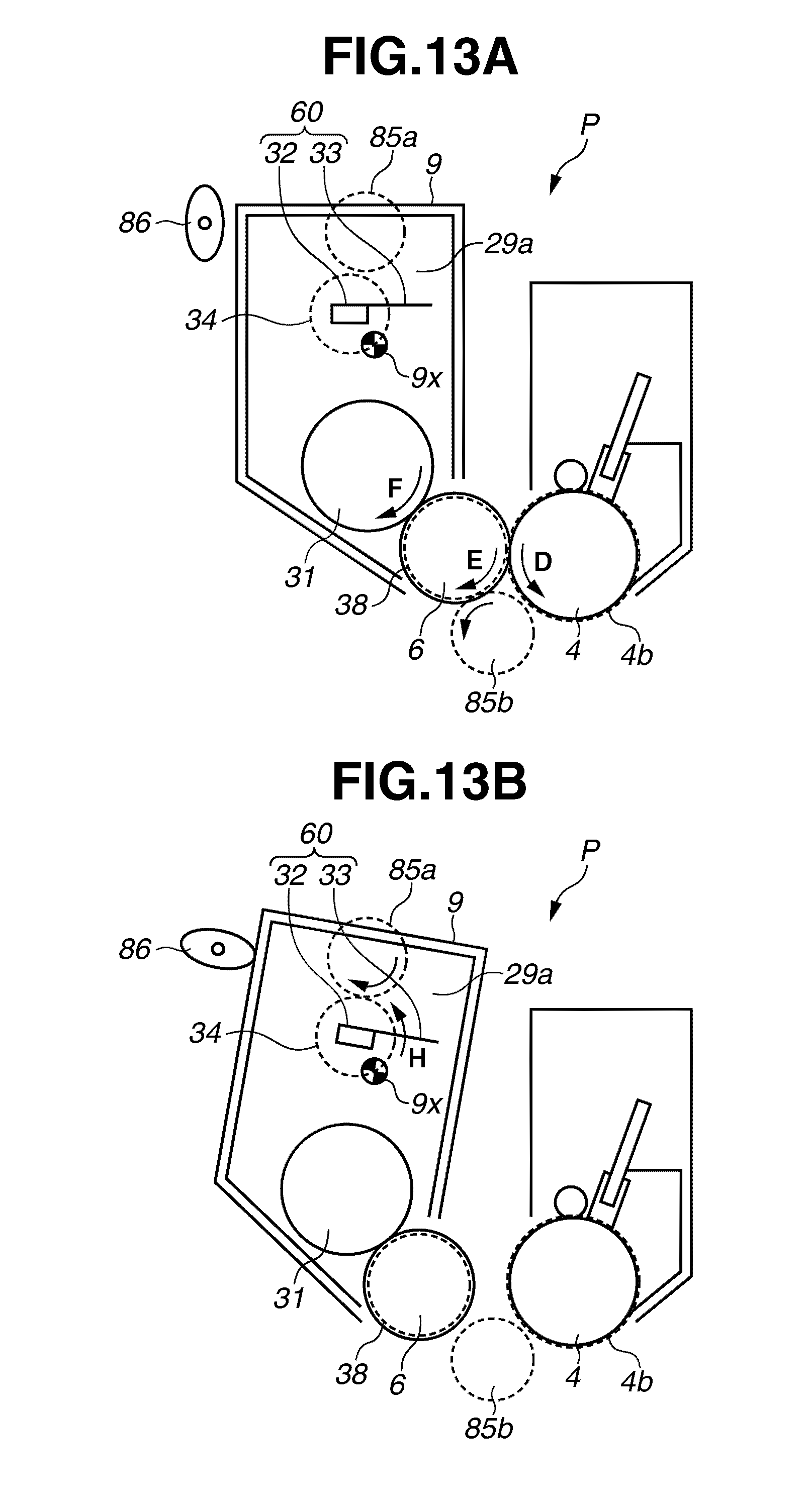
In the present exemplary embodiment, the control unit 100 (see