SPINAL SPACER DEVICES, TOOLS, AND METHODS
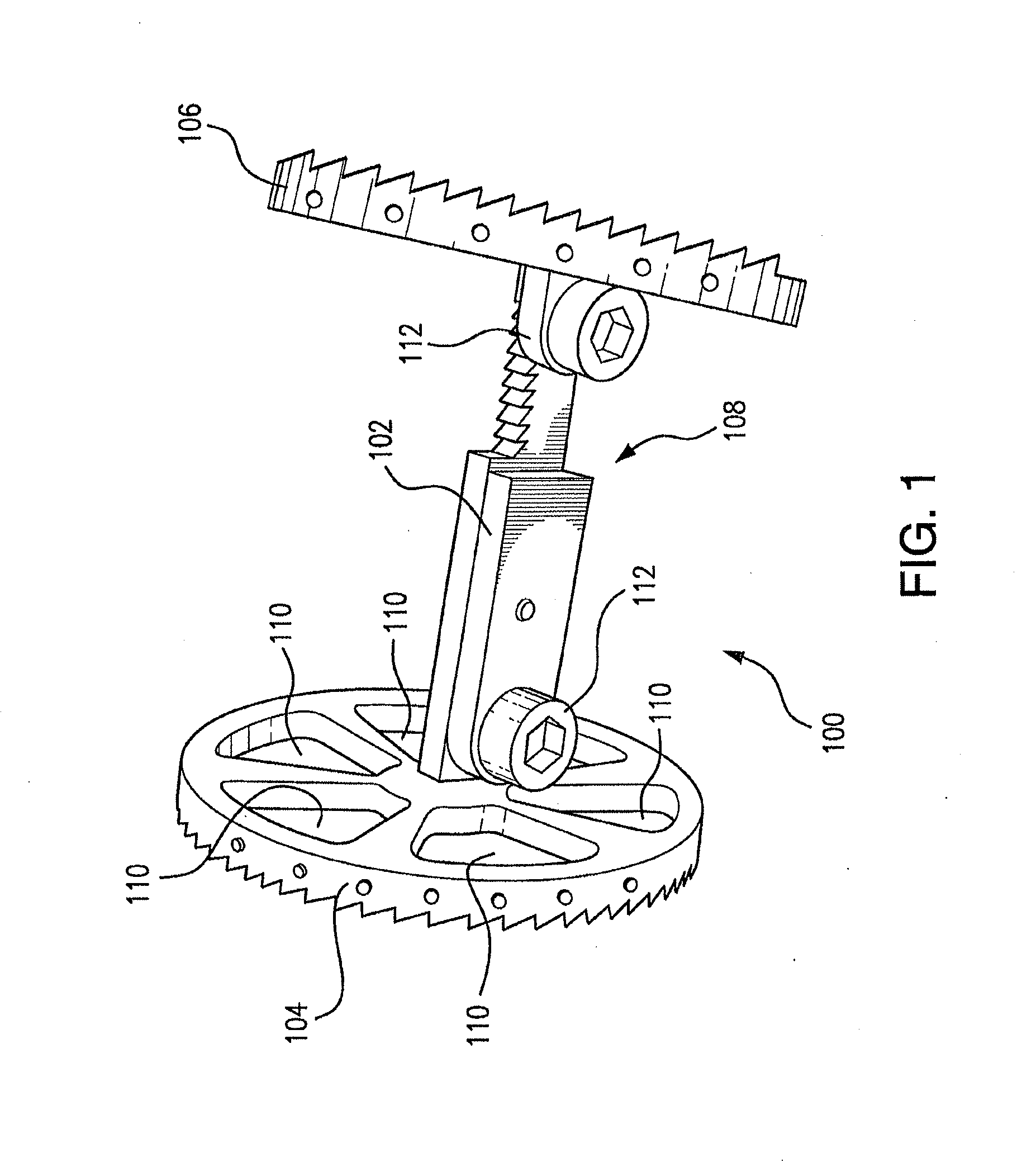
This application is a continuation of U.S. patent application Ser. No. 13/324,101 filed on Dec. 13, 2011, which claims the benefit of and priority to U.S. Provisional Patent Application No. 61/427,500, filed Dec. 28, 2010, both of which are incorporated by reference herein in their entirety. 1. Field of the Invention The present invention relates to orthopedic surgical procedures, and more particularly to tools, methods, and spinal spacer devices for spinal surgeries such as corpectomies, discectomies, and the like. 2. Description of Related Art A variety of devices are known in the art for fixation to the spine in surgical procedures for treating spinal conditions, such as corpectomies and discectomies. Among these devices are spacer devices such as those shown and described in U.S. Pat. No. 6,296,665 to Strnad et al., which can be used to maintain space between vertebrae after surgical removal of a spinal disc and/or vertebra. These fixation devices include upper and lower platforms joined by a core perpendicular thereto. The platforms have apertures therethrough for allowing surrounding bone to integrate with the fixation device. These devices are used to stabilize the spine and can be used to house bone or bone substitutes to help replace the natural structures removed from the spine. Bone may be held in place by an outer sleeve which is slipped around the apparatus. Such conventional methods and systems have generally been considered satisfactory for their intended purpose. However, there is still a need in the art for tools, methods, and devices that allow for improved containment of bone, bone substitutes, and the like, and that allow for improved visualization thereof. There also remains a need in the art for such devices, tools and methods that can facilitate adjustments to account for lordosis and the like. The present invention provides solutions for these problems. The subject invention is directed to a new and useful spacer device for spinal fixation, such as in corpectomies and discectomies. The spacer device includes a core and two end plates mounted to the core, one plate mounted to each respective end of the core. The core can be configured and adapted to be adjusted to allow for contraction and/or distraction of the end plates. The end plates can include apertures therethrough to facilitate osseointegration of the spacer device within a patient's spine. In certain embodiments, the angle of the endplates can each be adjusted with respect to the core of the spacer device, for example to accommodate lordosis. In accordance with another aspect, a containment mesh can be included around the spacer device, wrapping circumferentially around the end plates, and spanning from end plate to end plate. The containment mesh can thus define a containment volume between the end plates for containing bone replacement materials such as allograft or man-made materials. The invention also provides a tool for implanting spacer devices as described above. The tool includes means for adjusting the core of the spacer device to cause collapse/distraction of the endplates. The tool also includes means for clamping and releasing the spacer device. Means are also included for providing control to lock and unlock the spacer device. The invention also includes a method of using the spacer device and tool described above. The method includes adjusting the angle of the end plates relative to the core of the spacer device, clamping the spacer device with a tool for placing the spacer device, positioning the spacer device in a patient's spine, using the tool to distract the end plates of the spacer device, unclamping the spacer device to release the spacer device from the tool, placing bone replacement materials in a containment volume of the spacer device, and securing the bone replacement materials in the containment device by securing a mesh around the spacer device, wherein the mesh wraps around the spacer device and extends from end plate to end plate thereof. These and other features of the systems and methods of the subject invention will become more readily apparent to those skilled in the art from the following detailed description of the preferred embodiments taken in conjunction with the drawings. So that those skilled in the art to which the subject invention appertains will readily understand how to make and use the devices and methods of the subject invention without undue experimentation, preferred embodiments thereof will be described in detail herein below with reference to certain figures, wherein: Reference will now be made to the drawings wherein like reference numerals identify similar structural features or aspects of the subject invention. For purposes of explanation and illustration, and not limitation, a partial view of an exemplary embodiment of a spacer device constructed in accordance with the invention is shown in Referring now to Each end plate 104 and 106 forms a mechanism 112 with core 102 that is adjustable so that the angle of end plates 104 and 106 can each be independently adjusted with respect to core 102 of the spacer device. This allows a surgeon to set the plate angles to custom fit spacer device 100 in a patient's spine, such as to accommodate lordosis. Referring now to Once filled to a satisfactory extent with bone replacement materials, containment volume 126 can be closed off by completing the wrapping of mesh 122 around spacer device 100 as indicated by the large arrow in As shown in The lattice of mesh 122 is an open structure with extensibility for conformance to the adjustable end plates 104 and 106. Any suitable pore or cell size can be used, and it is contemplated that the cell size will be variable as spacer device 100 is manipulated. For example, it is contemplated that the relaxed cell size can be about ⅛ of an inch. The lattice can be fabricated using any suitable process, including for example, knit, braid, or other standard textile techniques producing an open structure with extensibility. The lattice can be made using a polymer or metal compatible with the biologic environment. One potential material is polypropylene, the material used to fabricate Prolene sutures. Other exemplary materials include, but are not limited to titanium, or nitinol, PEEK or biodegradable polymers. Individual lattice fibers an have a monofilament structure or can be fabricated by braiding or twisting a plurality of individual fibers. Those skilled in the art will readily appreciate that any suitable materials, lattice fiber structure, cell size, etc., can be used without departing from the spirit and scope of the invention. With reference now to Upper and lower grips 154 and 156 grip core 102 of spacer device 100, and trigger 160 can be pulled to open upper and lower clamps 154 and 156 and thereby release spacer device 100 from tool 150. A respective spring on each of the top and bottom clamps 154 and 156 keeps them normally open. Pulling back on trigger 160 opens clamps 154 and 156, and releasing trigger 160 causes clamps 154 and 156 to grasp, e.g., to grasp core 102 of spacer device 100. Upper and lower clamps 154 and 156 are connected to tool 150 by outer linkages 162 and inner linkages 164. Inner linkages 164 are pinned to a stationary point 166 that is stationary with respect to main shaft 168 of tool 150. Outer linkages 162 are pinned to a shaft within main shaft 168 that is axially moveable with respect to main shaft 168, and which is operatively connected to finger control 170. Finger control 170 can thus be manipulated toward or away from handle 172 to move upper and lower clamps 154 and 156 toward or away from one another. Thus, with pusher 152 releasing ratchet mechanism 108, finger control 170 can be used to distract and/or collapse end plates 104 and 106 as needed. This control configuration facilitates blind operation of tool 150. The invention also includes methods of using the spacer device 100 and tool 150 described above. Spacer device 100 is shown in The methods and systems of the present invention, as described above and shown in the drawings, provide for spinal spacer devices, methods, and tools with superior properties including improved containment and visualization of bone replacement materials, and improved adjustability. While the apparatus and methods of the subject invention have been shown and described with reference to preferred embodiments, those skilled in the art will readily appreciate that changes and/or modifications may be made thereto without departing from the spirit and scope of the subject invention. A spacer device for spinal fixation, such as in corpectomies and discectomies, includes a core and two end plates mounted to the core. One end plate is mounted to each respective end of the core. The core can be configured and adapted to be adjustable to allow for contraction and/or distraction of the end plates. The end plates can include apertures therethrough to facilitate osseointegration of the spacer device within a patient's spine. The angle of the endplates can each be adjusted with respect to the core of the spacer device, for example to accommodate lordosis. A containment mesh is included around the spacer device, wrapping circumferentially around the end plates, and spanning from end plate to end plate. The containment mesh defines a containment volume between the end plates for containing bone replacement materials such as allograft or man-made materials. 1. A spacer device for spinal fixation, comprising:
a core and two end plates mounted to the core, with one end plate mounted to each respective end of the core, wherein the core is configured and adapted to be adjusted to allow for contraction and distraction of the end plates; and a containment mesh wrapping circumferentially around the end plates, and spanning from end plate to end plate, wherein the containment mesh defines a containment volume between the end plates for containing bone replacement materials. 2. A spacer as recited in 3. A spacer as recited in 4. A tool for implanting a spacer device as recited in a) a handle and a main shaft; b) means for adjusting the core of the spacer device to cause collapse/distraction of the endplates, wherein the means for adjusting are operatively associated with the main shaft; c) means for clamping and releasing the spacer device, wherein the means for clamping and releasing are operatively associated with the main shaft; and d) means for providing control to lock and unlock the spacer device, wherein the means for providing control are operatively associated with the main shaft. 5. A method of placing a spacer device as recited in a) adjusting the angle of the end plates relative to the core of the spacer device; b) clamping the spacer device with a tool for placing the spacer device; c) positioning the spacer device in a patient's spine; d) using the tool to distract the end plates of the spacer device; e) unclamping the spacer device to release the spacer device from the tool; f) placing bone replacement materials in a containment volume of the spacer device; and g) securing the bone replacement materials in the containment device by securing a mesh around the spacer device, wherein the mesh wraps around the spacer device and extends from end plate to end plate thereof.CROSS-REFERENCE TO RELATED APPLICATIONS
BACKGROUND OF THE INVENTION
SUMMARY OF THE INVENTION
BRIEF DESCRIPTION OF THE DRAWINGS
DETAILED DESCRIPTION OF THE PREFERRED EMBODIMENTS