CONTROL METHOD FOR DRIVING A RIPPER
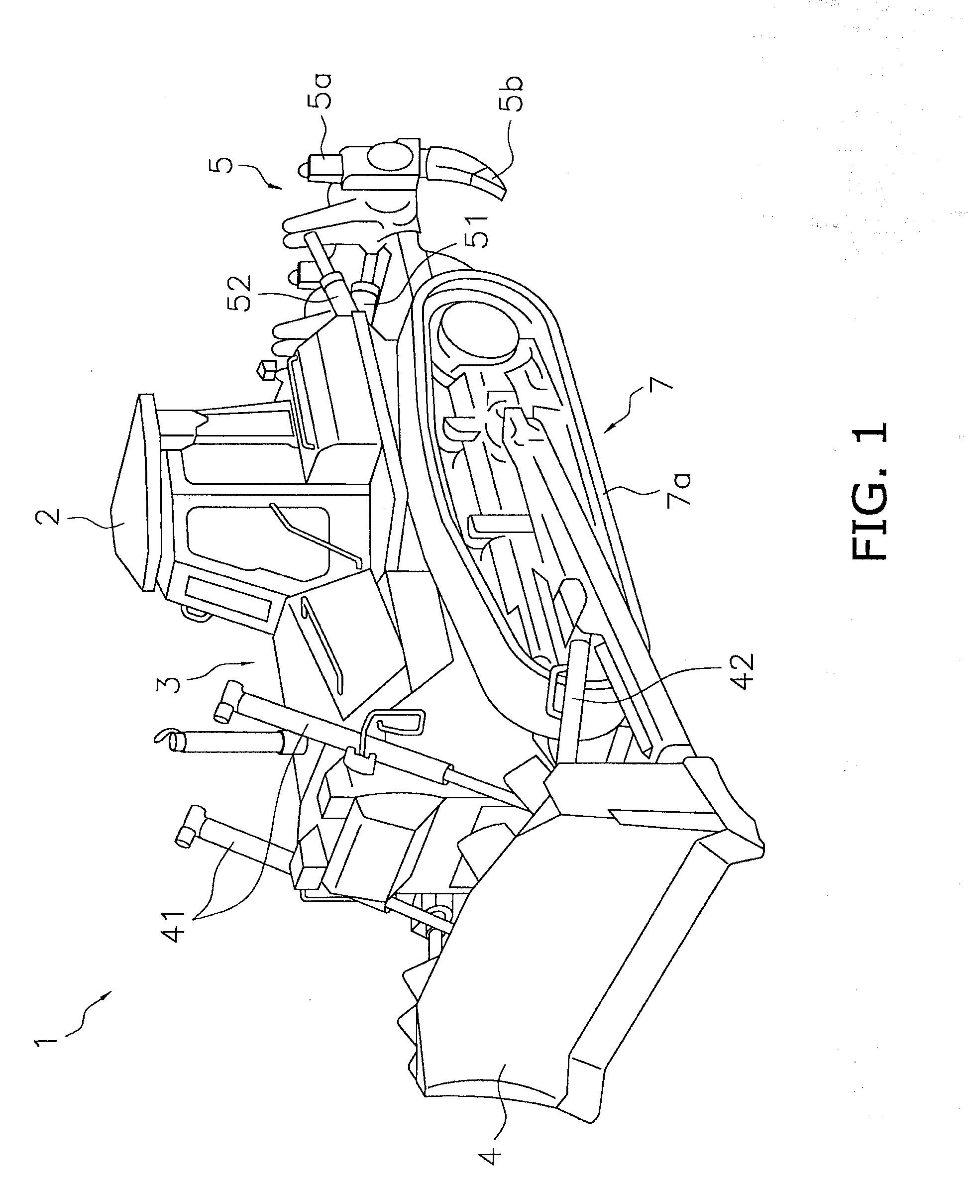
1. Field of the Invention The present invention relates to a control method for driving a ripper in order to perform digging and other such work. 2. Description of the Related Art In the past, a ripper mounted to the rear of the body of a bulldozer has been used to perform digging work in rock or hard soil. For example, as an apparatus for automatically controlling the ripping work of such a ripper, Patent Literature 1 discloses an apparatus in which an auto return button is provided for automatically lifting a ripper to a certain position when the button is pressed by the operator. However, the following problems were encountered with this conventional ripper drive control device. Specifically, with the ripper drive control device disclosed in the above-mentioned publication, the operator has to depress the auto return button in order to execute automatic control, so this entails operation other than the usual operation in ripping work. Accordingly, the operator has to add a new operation to the operation performed in ordinary ripping work, which is a problem in that the ripping work cannot be performed as same as in the past. It is an object of the present invention to provide a bulldozer with which less burden is imposed on the operator during ripping work, while allowing operation as same as in the past. The control method for driving a ripper pertaining to the present invention is a method for driving a ripper in which the movement of a ripper attached to the rear of the body of a bulldozer is controlled, said method comprising a first step in which it is detected that ripping work by the ripper has ended, and a second step in which a first control of pulling the ripper out of a ground and a second control of tilting back the ripper are selectively executed when it is detected that the ripping work has ended. The bulldozer 1 pertaining to an embodiment of the present invention will be described below through reference to Overall Configuration of Bulldozer 1 The bulldozer 1 pertaining to this embodiment is a construction machine that performs leveling on uneven ground. As shown in The cab 2 is equipped with an operator's seat (driver's seat) 11 for the operator to sit on, and levers, pedals, gauges, and so forth for performing various operations (see The drive unit 7 and the blade 4, ripper 5, and other such working mechanisms are attached to the vehicle body frame 3, and the cab 2 is installed on top of it. The blade 4 is provided in front of the vehicle body frame 3, is a work implement for scraping off the ground surface and pushing around earth, and is driven by hydraulic cylinders (a blade lift cylinder 41 and a blade tilt cylinder 42) according to the operation of a blade operating lever 31 (discussed below). The ripper 5 is provided to the rear of the vehicle body frame (body) 3. The ripper 5 thrusts a ripping tip 5 The drive unit 7 allows the bulldozer to travel over uneven ground by rotating a pair of endless crawler belts 7 Configuration of Cab 2 Interior As shown in The operator's seat 11 is the seat in which the operator sits after climbing into the cab 2, and performs driving operations, and this seat is installed so that it can slide forward and backward. The operator's seat 11 is also installed so as to be rotatable, so that the operator can more easily work the controls when operating the ripper 5, etc., while looking backward. Various operating levers and other such operational machinery that are operated by the operator are installed on the left and right sides of the operator's seat 11. As shown in The blade operating lever 31 is provided at the very front part of the upper surface of the right-hand controls 20, and actuates the blade lift cylinder 41 and blade tilt cylinder 42 that drive the blade 4 (see The ripper operating lever 32 is provided adjacent to and to the rear of the blade operating lever 31 on the upper face of the right-hand controls 20, and actuates the ripper lift cylinder 51 and ripper tilt cylinder 52 that drive the ripper 5 (see As shown in FIG. cab 2, the left-hand controls 21 are disposed on the left side of the operator's seat 11 as viewed by the operator when seated in the operator's seat 11. A steering lever 33, an armrest 34, and so forth are provided on the upper surface of the left-hand controls 21. The steering lever 33 is swiveled backward and forward and to the left and right when the forward direction of the vehicle is in front, thereby providing steering. The steering lever 33 also has a shift switch 33 The armrest 34 has a raised portion along its left edge, and this raised portion supports the operator's weight when the center of gravity shifts to the left side. The monitor 35 is a touch-sensitive panel type of display device disposed in front of the operator's seat 11. As shown in As shown in Flow of Ripping Work The flow of ripping work using the ripper 5 of the bulldozer 1 will now be described through reference to In ordinary ripping work using the ripper 5, the operator performs the work while performing various operations by the procedure shown in (1) The operator operates the ripper tilting lever 32 (2) The operator steps on the decelerator pedal in the cab 2 to lower the engine speed, and operates the shift switch 33 (3) When the ripping tip 5 (4) When the bulldozer 1 has advanced to the desired position and the ripping work ends, the operator operates the ripper lifting lever 32 (5) While reversing the bulldozer 1, the operator operates the ripper tilting lever 32 (6) When the bulldozer 1 has reversed to a position close to the next ripping start point, the operator operates the ripper lifting lever 32 Usually, in performing this ripping work, in the cab 2 shown in The operations in (4) and (5) here must be performed each time as preparatory work after performing one row of ripping work and until the next ripping work is to be performed. These operations must be carried out simultaneously, while checking ahead and behind, so this imposes a considerable burden on the operator. In particular, since the ripper operating lever 32 is provided on the right side of the operator's seat 11, and the steering lever 33 on the left side, in the cab 2 of the bulldozer 1 shown in Setting of Automatic Ripper Return Control In this embodiment, ripper automatic return control setting is performed by the following procedure in order to reduce the operational burden on the operator during the above-mentioned ripping work. Specifically, in performing automatic ripper return control (ripper auto return), as shown in FIG. 5 More specifically, when the operator turns a key in the cab 2 to switch on the system, as shown in Next, when the operator presses an automatic control function on/off button 62 Mode Setting of Automatic Ripper Return Control In this embodiment, this automatic ripper return control can be set to three different modes: control in which the operation of just (4) above (lift operation) is automated (first mode), control in which the operations of (4) and (5) above are automated so as to work independently (lift/tilt independent actuation) (second mode), and control in which the operations of (4) and (5) above are automated so as work in conjunction (linked lift/tilt operation). Thus, the operator selects among these three modes by performing the following procedure. Specifically, as shown in Then, as shown in As shown in Thus, the operator can have the control device 40 execute automatic ripper return control by selecting the work to be automated and depressing the select button 63 Flow of Automatic Ripper Return Control With the control device 40 installed in the bulldozer 1 of this embodiment, when the above-mentioned setting of automatic return control is complete, if all of the following specific conditions (steps S2 to S4) have been satisfied, the system switches from normal control to automatic ripper return control. On the other hand, after automatic ripper return control has started, if any of the following specific conditions (steps S6 to S9) have been satisfied, the system switches from automatic ripper return control to normal control. Automatic Lift Control First, of the operations performed after completion of ripping work discussed above, we will describe control in which the lifting of the ripper 5 is automated as in (4) shown in Specifically, as a result of the above-mentioned mode setting, when the lift-only selection button 64 In step S2, it is determined whether or not ripping work is in progress, and if it is, the flow proceeds to step S3, and otherwise returns to step S1. More specifically, the determination of whether or not ripping work is in progress is made by whether the ripper 5 has been lowered or tilted in while the bulldozer 1 is advancing, or whether the ripper 5 has been lowered while the bulldozer 1 is stopped. This avoids, for example, a situation in which the automatic ripper return control is accidentally performed during dozing work with the blade 4. In step S3, it is determined whether or not the bulldozer 1 is reversing, and if it is, the flow proceeds to step S4. Here, it is confirmed that the ripping work has ended and the bulldozer 1 is still reversing. In step S4, it is determined whether or not the operator has moved the ripper operating lever 32 to the lift position, and if so, the flow proceeds to step S5. Here, whether or not the ripper has been lifted can be detected from the position of the ripper operating lever 32. In step S5, since the condition that the ripping work has ended and automatic return control has started has been satisfied in steps S2 to S4, the control device 40 automatically lifts the ripper 5 by outputting a command to lift the ripper 5. Specifically, in this embodiment, if the operator even momentarily puts the ripper operating lever 32 in the lift position in a state in which ripping work is ended and the bulldozer is reversing in steps S2 and S3, after that the lift operation of the ripper 5 will be automatically continued even if the operator removes his hand from the ripper operating lever 32. Consequently, the operator can have the rest of the lift operation carried out automatically just by putting the ripper operating lever 32 in the lift position, just as with normal control, as a cue to start automatic ripper return control. Thus, the operator can concentrate on operating the steering lever 33 while reversing, and thereby move the bulldozer 1 to the next point where ripping work is to be started. As a result, part of the operation after the completion of ripping work can be automated while the operator performs the same operations as in ordinary ripping work, without having to depress any particular buttons or the like, and this reduces the operational burden on the operator. Next, in the following steps S6 to S9, we will describe the conditions for releasing this automatic ripper return control and switching to normal control. In this embodiment, as shown in In step S6, it is determined whether or not the bulldozer 1 is advancing or stopped. This is because if it is detected that the operator has operated the steering lever 33 in an effort to move forward from a state in which the bulldozer 1 is reversing, this recognizes a situation in which the operator is trying to go to the next ripping work, and releases the automatic ripper return control. In step S7, it is determined whether or not the work implement hydraulic pressure has been relieved in the hydraulic circuit. This is because the automatic ripper return control is stopped or cancelled if the system detects that the ripper 5 has been lifted or rotated, or that the blade 4 has been operated. The determination in step S7 is made on the basis of the detection result of the hydraulic sensor 36 In step S8, it is determined whether or not the ripper 5 has been lowered. That is, if the ripper operating lever 32 is in its lowering position, it is assumed that the operator is attempting to start the next ripping work, so the automatic ripper return control is released. This may be determined by detection of the position of the ripper operating lever 32. The automatic control can be effectively released by detecting operation in the opposite direction from that of the movement of the ripper 5 under the automatic control, and giving manual operation by the operator priority over automatic control. In step S9, it is determined from the output of the timer 39 whether or not a specific length of time has elapsed since the output of a ripper lift command from the control device 40. This assumes a case in which the automatic ripper return control is not properly released after its start based on the release conditions of steps S6 to S8, and is a release condition set for the purpose of safety. In this embodiment, as discussed above, when the automatic ripper return control is started, if any of the release conditions of steps S6 to S9 has been met, the automatic ripper return control is released and the system switches to normal control. If manual operation is then detected in which the operator has switched operation of the ripper operating lever 32 (from lifting to lowering) or operation of the steering lever 33 (from reversing to advancing), priority is given to manual operation over automatic control and the ripper 5 is stopped, which provides greater safety in automatic control. Automatic Tilt Control Next, of the operations after completion of the above-mentioned ripping work, we will describe control in which the tilting of the ripper 5 in (5) shown in Specifically, when the lift/tilt independent actuation selection button 64 More specifically, as shown in In step S2, it is determined whether or not ripping work is in progress, and if it is, the flow proceeds to step S13, and otherwise returns to step S11. More specifically, the determination of whether or not ripping work is in progress is made by whether the ripper 5 has been lowered or tilted in while the bulldozer 1 is advancing, or whether the ripper 5 has been lowered while the bulldozer 1 is stopped. This avoids, for example, a situation in which the automatic ripper return control is accidentally performed during dozing work with the blade 4. In step S13, it is determined whether or not the bulldozer 1 is reversing, and if it is, the flow proceeds to step S14. Here, it is confirmed that the ripping work has ended and the bulldozer 1 is still reversing. In step S14, it is determined whether or not the operator has moved the ripper operating lever 32 to the tilt-back position, and if so, the flow proceeds to step S15. Here, whether or not the ripper has been tilted back can be detected from the position of the ripper operating lever 32 (the ripper tilting lever 32 In step S15, since the condition that the ripping work has ended and automatic return control has started has been satisfied in steps S12 to S14, the control device 40 automatically tilts the ripper 5 back by outputting a command to tilt back the ripper 5. Specifically, in this embodiment, if the operator even momentarily puts the ripper operating lever 32 in the tilt-back position in a state in which ripping work is ended and the bulldozer is reversing in steps S12 and S13, after that the tilt-back operation of the ripper 5 will be automatically continued even if the operator removes his hand from the ripper operating lever 32. Consequently, the operator can have the rest of the tilt-back operation carried out automatically just by putting the ripper operating lever 32 in the tilt-back position, just as with normal control, as a cue to start automatic ripper return control. Thus, the operator can concentrate on operating the steering lever 33 while reversing, and thereby move the bulldozer 1 to the next point where ripping work is to be started. As a result, part of the operation after the completion of ripping work can be automated while the operator performs the same operations as in ordinary ripping work, without having to depress any particular buttons or the like, and this reduces the operational burden on the operator. Next, in the following steps S16 to S19, we will describe the conditions for releasing this automatic ripper return control and switching to normal control. In this embodiment, as shown in In step S16, it is determined whether or not the bulldozer 1 is advancing or stopped. This is because if it is detected that the operator has operated the steering lever 33 in an effort to move forward from a state in which the bulldozer 1 is reversing, this recognizes a situation in which the operator is trying to go to the next ripping work, and releases the automatic ripper return control. In step S17, it is determined whether or not the work implement hydraulic pressure has been relieved in the hydraulic circuit. This is because the automatic ripper return control is stopped or cancelled if the system detects that the ripper 5 has been lifted or rotated, or that the blade 4 has been operated. In step S18, it is determined whether or not the ripper 5 has been tilted in. That is, if the ripper operating lever 32 is in its tilt-in position, it is assumed that the operator is attempting to start the next ripping work, so the automatic ripper return control is released. This may be determined by detection of the position of the ripper operating lever 32. The automatic control can be effectively released by detecting operation in the opposite direction from that of the movement of the ripper 5 under the automatic control, and giving manual operation by the operator priority over automatic control. In step S19, it is determined from the output of the timer 39 whether or not a specific length of time has elapsed since the output of a tilt-back command from the control device 40. This assumes a case in which the automatic ripper return control is not properly released after its start based on the release conditions of steps S16 to S18, and is a release condition set for the purpose of safety. In this embodiment, as discussed above, when the automatic ripper return control is started, if any of the release conditions of steps S16 to S19 has been met, the automatic ripper return control is released and the system switches to normal control. If manual operation is then detected in which the operator has switched operation of the ripper operating lever 32 (from tilt-back to tilt-in) or operation of the steering lever 33 (from reversing to advancing), priority is given to manual operation over automatic control and the ripper 5 is stopped, which provides greater safety in automatic control. When the lift/tilt independent actuation selection button 64 Lift/Tilt Gang Automatic Control Next, of the operations after completion of the above-mentioned ripping work, we will describe control in which the lifting and tilting of the ripper 5 in (4) and (5) shown in Specifically, when the lift/tilt linked actuation selection button 64 More specifically, as shown in That is, when a mode is set for performing lift/tilt linked automatic control (third mode), it is determined whether or not the conditions of steps S2, S3, and S4 are satisfied in order starting from the normal control state in step S1, and if all the conditions have been met, in step S5 the control device 40 outputs a ripper lift command, and lifting operation is automatically carried out. Next, when the release conditions in steps S6 to S9 are satisfied, the lifting operation is stopped, and in step S15 the control device 40 outputs a tilt-back command to start automatic tilt control. That is, in this mode, the automatic tilt control is started using the fact that automatic lift control has been released as a condition, without determining the various conditions for performing automatic tilt-back control (steps S12 to S14 in Just as with the automatic tilt control shown in As discussed above, in this embodiment, the operator can selected from among three modes according to his preference. An embodiment of the present invention was described above, but the present invention is not limited to or by the above embodiment, and various modifications are possible without departing from the gist of the invention. (A) In the above embodiment, examples were given for conditions for starting and releasing automatic ripper return control, but the present invention is not limited to or by these. For example, other conditions may be added for starting or releasing the control, or some of the above-mentioned starting and releasing conditions may be omitted. (B) In the above embodiment, an example was given in which the above-mentioned automatic tilt control was performed only when lift/tilt independent actuation (second mode) and lift/tilt linked actuation (third mode) were selected, but the present invention is not limited to or by this. For example, automatic tilt control can also be selected by itself on the setting screen. The bulldozer of the present invention has the effect of considerably reducing the operational burden on the operator during ripping work without having to depressing any particular control button or the like as compared to that in the past, and therefore can be widely applied to work vehicles equipped with a ripper. The control method for driving a ripper pertaining to the eight invention is a method for driving a ripper in which the movement of a ripper attached to the rear of the body of a bulldozer is controlled, said method comprising a first step in which the ripper is operated while the bulldozer is moving forward or is stopped, a second step in which the bulldozer is reversed and the ripper is raised, and a third step in which the ripper is automatically raised. 1. A control method for driving a ripper, in which the movement of a ripper attached to the rear of the body of a bulldozer is controlled, said method comprising:
a first step in which it is detected that ripping work by the ripper has ended; a second step in which a first control of pulling the ripper out of a ground and a second control of tilting back the ripper are selectively executed when it is detected that the ripping work has ended. 2. The control method for driving a ripper according to wherein a first mode of executing the first control selectively is set in the second step. 3. The control method for driving a ripper according to wherein the first control is executed when it is detected that the ripping work has been ended by moving the steering lever to the reverse side during ripping work and by raising the ripper with the operating lever, in the second step. 4. The control method for driving a ripper according to wherein the second control is executed when it is detected that the steering lever has been moved to the reverse side during ripping work and tilt-back has been performed with the operating lever of the ripper, in the second step. 5. The control method for driving a ripper according to further comprising a third step in which the first control is released when it is detected that the hydraulic pressure in the hydraulic circuit of the bulldozer has risen over a specific relief pressure, or that the bulldozer is moving forward or is stopped, or that the ripper has been lowered with the operating lever, or that at least a specific amount of time has elapsed since the ripper was raised. 6. The control method for driving a ripper according to further comprising a third step in which the second control is released when it is detected that the hydraulic pressure in the hydraulic circuit of the bulldozer has risen over a specific relief pressure, or that the bulldozer is moving forward or is stopped, or that the ripper has been tilted in with the operating lever, or that at least a specific amount of time has elapsed since the ripper was tilted back. 7. The control method for driving a ripper according to wherein a second mode in which the first and second controls are executed independently, and a third mode in which the first and second controls are executed in conjunction are set in the second step. BACKGROUND OF THE INVENTION
CITATION LIST
Patent Literature
SUMMARY OF THE INVENTION
Problem to be Solved by the Invention
Means for Solving Problem
BRIEF DESCRIPTION OF DRAWINGS
DETAILED DESCRIPTION OF THE INVENTION
OTHER EMBODIMENTS
INDUSTRIAL APPLICABILITY