Efficient and Eco-friendly Oil Drilling System and Method
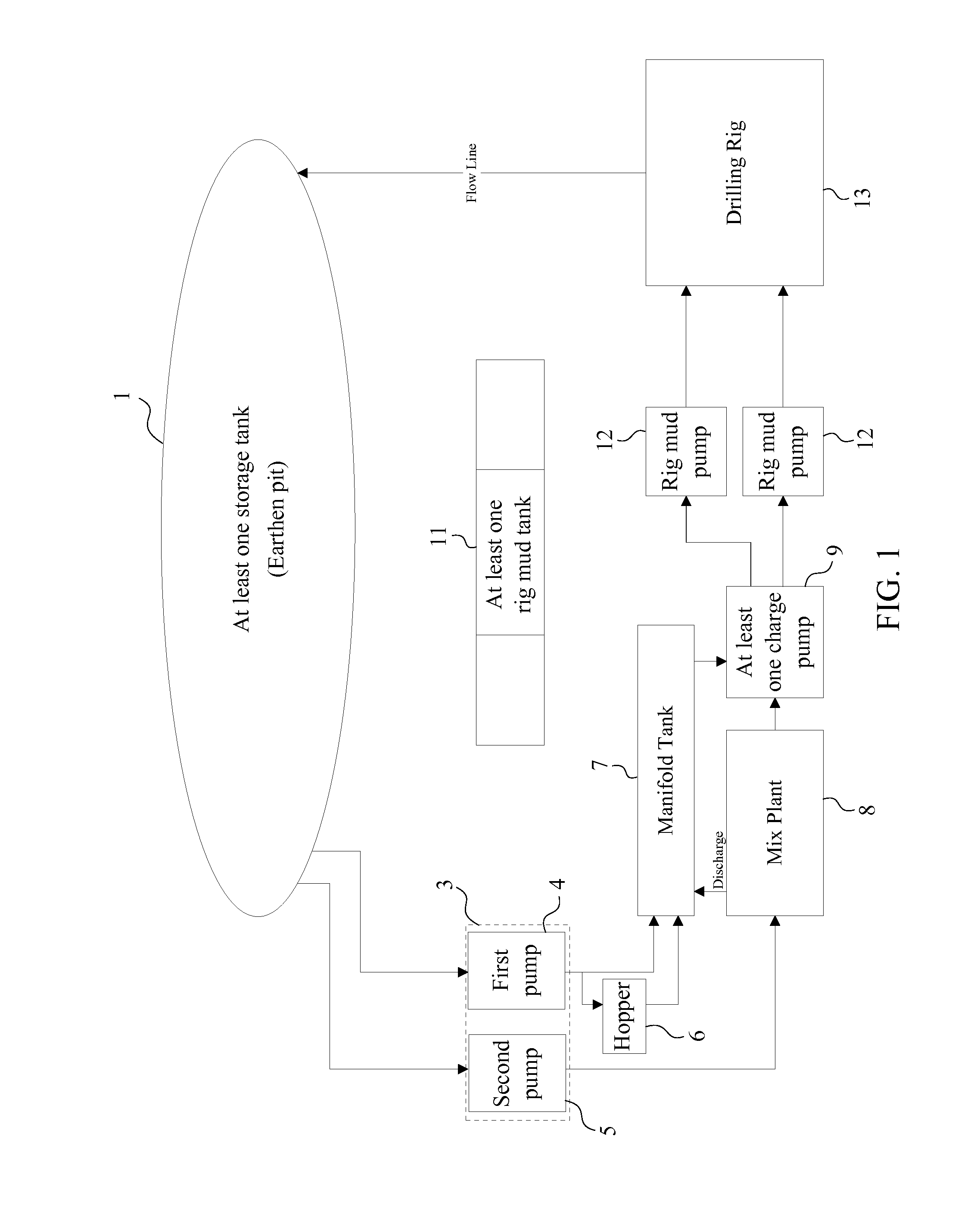
The current application claims a priority to the U.S. Provisional Patent application Ser. No. 61/866,131 filed on Aug. 15, 2013. The present invention relates generally to the process of drilling through the earth. More specifically, the present invention is a surface drilling eco-treatment system and method which is specially designed to help improve the drilling process by reducing the amount of time needed to complete the drilling process, reducing the overall cost of the drilling process, and reducing the chances of spilling oil based fluids which can damage the environment. Throughout history people have been inventing new forms of technology which are meant to perform new tasks, make day to day life easier, and to make possible feats which are simply impossible without technology. There is an incredibly broad range of technological advancements which have been made over the years from simple products like forks and cups to advanced machines like motorized vehicles and fighter jets. There is however one major trend which can be observed the technological advancement of humankind. This observable trend is the ever increasing reliance on power generation in order to drive the operation of an ever increasing number of power consuming machines and devices. Two of the best and most widespread examples of human power consumption are consumer electronics and motor vehicles. Consumer electronics is a category which includes any device that can be purchased on the open market for personal use by one or more people. Most if not all consumer electronics require electricity in order to function. Although many modern consumer electronics are portable and have a portable electricity storage unit, these units must be charged from a primary source, such as a wall outlet. Wall outlets across the nation are supplied with electricity by power plants. Motor vehicles are the other major source of energy consumption in the modern world, and an extremely large percentage of all motor vehicles rely upon fossil fuels in order to operate. Most motor vehicles utilize some form of combustion in order to generate mechanical torque upon a driveshaft. This torque is then transferred to the wheels of the vehicle, allowing it to travel at great speeds over a relatively smooth surface. Internal combustion engines utilize combustible fuels such as gasoline and diesel in order to operate. These fuels are refined products of a fossil fuel known as petroleum or crude oil. Crude oil is a naturally occurring substance which is found in geological formations below the earth's surface. It is theorized that crude oil is the result of large quantities of dead organisms being exposed to incredible heat and pressure over millions of years, eventually forming the flammable substance we known as petroleum. Petroleum is refined into various different fuels which are used to power the world's billions of motorized vehicles. However, before petroleum can be refined into fuels, it must be extracted from below the earth's surface. Crude oil is typically extracted from below the surface of the earth through a process commonly called oil drilling. The actual drilling is only done until the oil reservoir is reached, after which point a pump is installed to physically extract the crude oil. Oil drilling is performed with the assistance of large and complex machines known as drilling rigs. These machines enable workers to bore a circular hole through the earth down to the depth where the oil is located. There are generally two main stages of drilling for oil. The first stage is surface drilling, and is typically done with water mixtures flushed continuously through the borehole. These water mixtures are intended to flush out cuttings and condition the borehole walls with chemicals to help prevent cave ins of the borehole. The present invention is focused mainly on the surface drilling stage; however the next stage is also important and comprises the use of oil based mud to lubricate the drill bit during drilling and to flush cuttings out of the borehole. Conventional drilling processes typically use water filled into the rig tanks during the surface stage. Once the surface stage is completed, the rig tanks have to be thoroughly cleaned out, and the oil based mud has to be pumped into the rig tanks in preparation for the next stage of the drilling process. It is very important that the rig tanks be thoroughly cleaned of all water and any particulate matter because the oil based mud will not function properly if contaminated. Oil based mud used in drilling is extremely expensive and is often rented out. If any volume of the oil is contaminated and subsequently lost, then the drilling company must pay for that oil based mud, as well as paying to dispose of the contaminated oil based mud. This can be very expensive, and is best avoided. Unfortunately, the cumbersome process of emptying the rig tanks of oil based mud and filling them with water, only to later remove the water and clean the tanks makes it all too easy for an accident to occur and contaminate the oil based mud. It is an object of the present invention to eliminate the need to empty the rig tanks and fill them with water during the surface drilling process. The present invention provides a system and a method for surface drilling which allows the oil based mud to remain isolated within the rig tanks until it is needed in the later stages of drilling. By minimizing the transfer of the oil based mud, the chances of it becoming contaminated, or of the oil based mud spilling, is drastically reduced. Thus the present invention is highly advantageous when compared to current methodologies of surface drilling in the oil industry. All illustrations of the drawings are for the purpose of describing selected versions of the present invention and are not intended to limit the scope of the present invention. The present invention is an efficient and eco-friendly oil drilling system and method which are specifically designed to streamline the different drilling stages which takes place when a borehole is created by a drilling process. The system of the present invention comprises a unique arrangement of well known technologies which enable a new method of drilling to be carried out. Currently utilized well drilling methods include many cumbersome, expensive, and time intensive steps which are eliminated through the use of the system and method of the present invention. The present invention not only decreases time and money costs of drilling a new oil well, but also drastically decreases the chances of environmental contamination of the surrounding area by removing several standard steps in which such environmental contamination is most likely to occur. The system of the present invention includes all the physical components and the connections between those components which enable the method of the present invention to be carried out. Without the system, the method of the present invention cannot be carried out. Thus the system is a very important part of the present invention. In reference to The at least one storage tank 1 of the system of the present invention, which stores water-based drilling fluid, can be either an earthen pit or a plurality of circulating tanks. The earthen pit is a large hole that is dug into the ground and often lined with some kind of water impermeable material such as a plastic sheet. The primary purpose of the earthen pit is to provide a volume for the storage of the water-based drilling fluid which is used within the system and to provide storage for cuttings which are removed from the ground as the drilling process of the drilling rig 13 creates the borehole. The earth pit may vary greatly in both diameter and depth within the present invention to accommodate for multiple boreholes. Most drilling sites utilize the earthen pit for the purposes as listed above, however in some cases it is necessary to utilize an alternative method. In such cases, the earthen pit is replaced with the plurality of circulating tanks. These large volume circulating tanks provide the means to store excess water-based drilling fluid and to collect the cuttings from the drilling process. The plurality of circulating tanks is useful if the oil well is drilled in an area where the ground is unsuitable for an earthen pit, or where the environment is too fragile, and the cuttings and excess water-based drilling fluid from the drilling process must be better contained to help prevent damage to the surrounding environment. Each of the plurality of circulating tanks is in fluid communication with each other and generally positioned in a series configuration as can be seen in The initial surface drilling system 2 comprises a plurality of transfer pumps 3, a hopper 6, a manifold tank 7, a mix plant 8, and at least one charge pump 9. The plurality of transfer pumps 3 is in fluid communication with the at least one storage tank 1 as shown in In reference to The manifold tank 7 is a large, rectangular shaped storage volume that is intended to hold a minimum capacity level of the water-based drilling fluid necessary for the drilling process to continue. The manifold tank 7 is in fluid communication with the at least one charge pump 9 directly and comprises a skid which is attached to the bottom of the manifold tank 7, and is manufactured from either steel or stainless steel. The primary purpose of the manifold tank 7 is to ensure that the at least one charge pump 9 is continuously supplied with the minimum necessary amount of the water-based drilling fluid for the drilling process to continue uninterrupted. If the water-based drilling fluid level within the system drops too low, the at least one charge pump 9 would be pumping air, and the drilling process would be compromised. The manifold tank 7 prevents this by continually storing a large volume of the water-based drilling fluid. The second pump 5 is in fluid communication with the mix plant 8 directly in such a way that a single connection line is positioned in between the second pump 5 and the mix plant 8. The mix plant 8 comprises a large circular or rectangular storage tank 1 which is skidded with either steel or stainless steel components. The primary purpose of the mix plant 8 is the preparation a secondary solution that must be mixed separately from the primary flow of the water-based drilling fluid which is contained within the manifold tank 7. The secondary solution can be important to the proper drilling process and must be mixed properly in order to achieve the desired effects of the drilling process. As can be seen in Since the at least one charge pump 9 is in fluid communication with both the manifold tank 7 and the mix plant 8, the at least one charge pump 9 is able to create a drilling fluid as the secondary solution from the mix plant 8 and the water-based drilling fluid from the manifold tank 7 are mixed within the at least one charge pump 9. Then the at least one charge pump 9 evenly and continuously pumps the drilling fluid into the plurality of rig mud pumps 12. Additionally, the at least one charge pump 9 ensures that the drilling fluid into the plurality of rig mud pumps 12 and the fluid pressure within the plurality of rig mud pumps 12 are sufficient enough for the system of the present invention. This ensures that no cavitation occurs within the plurality of rig mud pumps 12 which could otherwise damage the initial surface drilling system 2. The at least one charge pump 9 may be powered by either diesel, electricity, or any other suitable power source. The plurality of rig mud pumps 12 that is integrated into the system of the present invention is actually a component of the drilling rig 13. The plurality of rig mud pumps 12 is responsible for pumping the drilling fluid into the borehole during the drilling process. The continuous pumping of the drilling fluid into the borehole performs several important functions including, but are not limited to, conditioning the walls of the borehole, lubricating the drill bit, carry information about the formation being drilled, reduce heat, and flushing out the cuttings. The drilling rig 13 is responsible for providing the torque and machinery necessary to actually cut the borehole through the surface. The drilling rig 13 may be any drilling rig 13 suitable for this sort of oil drilling. The drilling fluid and the cuttings flow out of the borehole and back into the at least one storage tank 1 through the connecting line as shown in The subsequent drilling system 10 is generally utilized within the system of the present invention after the initial surface drilling system 2 so that the later stages of the drilling process can be finalized through the present invention. The subsequent drilling system 10 comprises at least one rig mud tank 11 that is in fluid communication with the plurality of rig mud pumps 12. More specifically, the at least one rig mud tank 11 stores an oil-based drilling fluid for the later stages of the drilling process. When the subsequent drilling system 10 is in fluid communication with the plurality of rig mud pumps 12, the at least one rig mud tank 11 provides the oil-based drilling fluid through the subsequent drilling system 10 so that the drilling process can be completed for the oil well. The method of the present invention comprises the process of utilizing the system to perform oil well drilling in a much more efficient and environment friendly manner than currently utilized methods. In reference to First the drilling rig 13 is moved into a specific location so that the oil well can be drilled through the system of the present invention. Then the drilling rig 13 is prepared on the specific location in order to drill the borehole. This process also is known as the rig up process within the oil drilling industry. After the rig up process, the initial surface drilling system 2 is connected to the drilling rig 13 through the plurality of rig mud pumps 12 and then the specific location is drilled by the drilling rig 13 in order to create a surface hole of for the borehole, where the surface hole is drilled by way of well known methodologies in the field of oil drilling. Simultaneously, the drilling fluid is pumped into the surface hole from the initial surface drilling system 2. During the creation of surface hole, the water-based drilling fluid is directly transferred into the manifold tank 7 through the first pump 4. Simultaneously, the water-based drilling fluid is indirectly transferred into the manifold tank 7 through the first pump 4 and the hopper 6 so that the water-based drilling fluid is able to mix with the at least one detergent that are stored within the hopper 6. Additionally, the water-based drilling fluid is directly transferred into the mix plant 8 through the second pump 5 as the water-based drilling fluid within the mix plant 8 is thoroughly mixed with additives to create the secondary solution Then the secondary solution is discharged into the manifold tank 7 from the mix plant 8 so that the secondary solution can be mixed with the water-based drilling fluid. It is important that the manifold tank 7 is filled with a sufficient amount of the water-based drilling fluid or else the system of the present invention does not function properly during the drilling process of the oil well. Then the water-based drilling fluid from the manifold tank 7 and the secondary solution from the mix plant 8 are transferred into the at least one charge pump 9 in order to create the drilling fluid. Then the drilling fluid is pumped into the plurality of mud pumps so that the drilling fluid can be discharged into the surface hole by the drilling rig 13. As long as the drilling rig 13 continuously utilizes the initial surface drilling system 2, the drilling fluid circulates back into the at least one storage tank 1 through the drilling rig 13. Once the surface hole is drilled to the desired depth as defined by the surface stage of oil well, a first casing setup is installed for the surface hole so that the first casing setup is able to isolate the surface hole from the surrounding environment. More specifically, the first casing setup is concentrically placed within the surface hole and cemented to the surrounding environment so that the first casing set is secured within the surface hole. Once the first casing setup is installed, the initial surface drilling system 2 is disconnected from the plurality of rig mud pumps 12 so that the subsequent drilling system 10 can be connected to the plurality of rig mud pumps 12. The subsequent drilling system 10 is utilized within the method of present invention so that the surface hole can be drilled into the reservoir of oil. After the attachment of the subsequent drilling system 10, the drilling rig 13 further drills the surface hole to complete the borehole. The drilling rig 13 simultaneously pumps the oil-based drilling fluid into the borehole from the subsequent drilling system 10, where the oil-based drilling fluid circulates back into the subsequent drilling system 10. This is the major source of the advantage of the present invention. In one quick step, the oil-based drilling fluid can be utilized by the drilling rig 13 through the connection of the subsequent drilling system 10 to the rig mud pumps 12. Other traditional methods must spend valuable time cleaning out the rig tanks and then retuning the oil-based drilling fluid to the rig tanks after surface hole is drilled. The present invention avoids this altogether by simply isolating the at least one rig mud tank 11 during the initial surface drilling system 2. This is illustrated in After the borehole is created by the drilling rig 13, a second casing setup is installed for the borehole so that the second casing setup is able to isolate the borehole from the surrounding environment. More specifically, the second casing setup is concentrically placed within the borehole and connected to the first casing setup. Then the second casing setup is cemented to the surrounding environment to secure the second casing setup within the borehole. The drilling process of the vertical and lateral sections of the oil well, along with the placing of the first casing and the second casing, and the cementing of the first casing and the second casing are well known in the field of oil drilling and does not need to be further defined in this description. Then the subsequent drilling system 10 is disconnected from the plurality of rig mud pumps 12 so that the drilling rig 13 is once again able to perform the drilling process for a next location. More specifically, the drilling rig 13 is skidded into the next location where the next oil well is to be drilled, and the method of the present invention repeats itself. As the final stage of oil well, a production wellhead is installed onto the first casing setup along with the other necessary equipments so that the oil well is able to produce oil. In this manner, the method defines the continuous nature of oil drilling as the drilling rig 13 is moved into each different location. Once borehole is drilled, and the drilling rig 13 is moved to the next location to drill yet another borehole. The major advantages of the method of the present invention are the fact that many steps from the original process are eliminated. The most notable advantage is the fact that the method of the present invention allows the surface drilling to be done without the need to empty the rig tanks. In the old process the rig tanks had to be emptied, cleaned, and filled with the drilling fluid for the drilling of the surface hole. Once the drilling for the surface hole is completed, the rig tanks would be emptied of the drilling fluid, cleaned, and filled with oil-based drilling fluid. The present invention eliminates the need for those steps, and in so doing reduces the time, the cost, and the environmental impact of the drilling process. This is particularly true since moving the oil-based drilling fluid invites disaster in the form of a spill, or in the contamination of the extremely expensive fluid. The system and method of the present invention is a great improvement upon other methods by implementing the system to allow elimination of the costly steps. Although the invention has been explained in relation to its preferred embodiment, it is to be understood that many other possible modifications and variations can be made without departing from the spirit and scope of the invention as hereinafter claimed. An efficient and eco-friendly oil drilling system includes at least one storage tank, an initial surface drilling system and a subsequent drilling system, a plurality of rig mud pumps, and a drilling rig. The plurality of rig mud pumps is in fluid communication with the drilling rig as the drilling rig is in fluid communication with the at least one storage tank. The initial surface drilling system that drills a surface hole for an oil well and the subsequent drilling system that drills a borehole for the oil well are selectively in fluid communication with the plurality of rig mud pumps, where the initial surface drilling system is utilized prior to the subsequent drilling system to optimize the efficiency of the drilling process. 1. An efficient and eco-friendly oil drilling system comprises:
at least one storage tank; an initial surface drilling system; a subsequent drilling system; a plurality of rig mud pumps; a drilling rig; the initial surface drilling system comprises a plurality of transfer pumps, a hopper, a manifold tank, a mix plant, and at least one charge pump; the subsequent drilling system comprises at least one rig mud tank; the plurality of rig mud pumps being in fluid communication with the drilling rig; the drilling rig being in fluid communication with the at least one storage tank; and the initial surface drilling system and the subsequent drilling system being selectively in fluid communication with the plurality of rig mud pumps, wherein the initial surface drilling system is utilized prior to the subsequent drilling system. 2. The efficient and eco-friendly oil drilling system as claimed in the initial surface drilling system; the at least one storage tank being in fluid communication with a first pump and a second pump of the plurality of transfer pumps; the first pump being in fluid communication with the manifold tank; the second pump being in fluid communication with the mix plant; the mix plant being in fluid communication with manifold tank and the at least one charge pump; the manifold tank being in fluid communication with the at least one charge pump; and the at least one charge pump being in fluid communication with the plurality of rig mud pumps. 3. The efficient and eco-friendly oil drilling system as claimed in the first pump being in fluid communication with the manifold tank directly. 4. The efficient and eco-friendly oil drilling system as claimed in the first pump being in fluid communication with the manifold tank through the hopper. 5. The efficient and eco-friendly oil drilling system as claimed in the subsequent drilling system; and the at least one rig mud tank being in fluid communication with the plurality of rig mud pumps, wherein the at least one rig mud tank stores an oil-based drilling fluid. 6. The efficient and eco-friendly oil drilling system as claimed in the at least one storage tank being an earthen pit, wherein the earthen pit stores a water-based drilling fluid. 7. The efficient and eco-friendly oil drilling system as claimed in the at least one storage tank being a plurality of circulating tanks, wherein the plurality of circulating tanks stores a water-based drilling fluid. 8. A method for efficient and eco-friendly oil drilling system as claimed in (1) providing a specific location with the at least one storage tank, the initial surface drilling system, the subsequent drilling system, the plurality of rig mud pumps, and the drilling rig; (2) positioning and preparing the drilling rig on the specific location in order to drill a borehole; (3) connecting the initial surface drilling system to the drilling rig through the plurality of rig mud pumps; (4) drilling the specific location by the drilling rig in order to create a surface hole for the borehole; (5) simultaneously pumping a drilling fluid into the surface hole from the initial surface drilling system, wherein the drilling fluid is circulate back into the at least one storage tank; (6) installing a first casing setup for the surface hole, wherein the first casing setup isolate the surface hole from the surrounding environment; (7) disconnecting the initial surface drilling system and connecting the subsequent drilling system to the drilling rig through the plurality of rig mud pumps; (8) drilling the surface hole by the drilling rig in order to complete the borehole, wherein the borehole extends into a reservoir of oil; (9) simultaneously pumping the oil-based drilling fluid into the borehole from the subsequent drilling system, wherein the oil-based drilling fluid circulates back into the subsequent drilling system; (10) installing a second casing setup for the borehole, wherein the second casing setup isolate the borehole from the surrounding environment; (11) disconnecting the subsequent drilling system from the plurality of rig mud pumps; and (12) repeating steps 1-10 for a next location. 9. The method for efficient and eco-friendly oil drilling system as claimed in directly transferring the water-based drilling fluid into the manifold tank through the first pump, wherein the water-based drilling fluid is stored within the at least one storage tank; indirectly transferring the water-based drilling fluid into the manifold tank through the first pump and the hopper in order to mix with at least one detergent; directly transferring the water-based drilling fluid into the mix plant through the second pump in order to create a secondary solution; discharging the secondary solution into the manifold tank from the mix plant, wherein the secondary solution is mixed with the water-based drilling fluid; transferring the water-based drilling fluid from the manifold tank and the secondary solution from the mix plant into the at least one charge pump in order to create the drilling fluid; pumping the drilling fluid into plurality of rig mud pumps through the at least one charge pump; discharging the drilling fluid into the surface hole by the drilling rig; and circulating the drilling fluid back into the at least one storage tank by the drilling rig. 10. The method for efficient and eco-friendly oil drilling system as claimed in discharging the oil-based drilling fluid into the borehole through the drilling rig, wherein the oil-based drilling fluid is stored within the at least one rig mud tank; and circulating the oil-based drilling fluid back into the subsequent drilling system by the drilling rig. 11. The method for efficient and eco-friendly oil drilling system as claimed in concentrically placing the first casing setup within the surface hole; and cementing the first casing setup to the surrounding environment. 12. The method for efficient and eco-friendly oil drilling system as claimed in concentrically placing the second casing setup within the borehole; connecting the second casing setup to the first casing setup; and cementing the second casing setup to the surrounding environment.FIELD OF THE INVENTION
BACKGROUND OF THE INVENTION
BRIEF DESCRIPTION OF THE DRAWINGS
DETAIL DESCRIPTIONS OF THE INVENTION