COMPRESSION-RELEASE ENGINE BRAKE SYSTEM FOR LOST MOTION ROCKER ARM ASSEMBLY AND METHOD OF OPERATION THEREOF
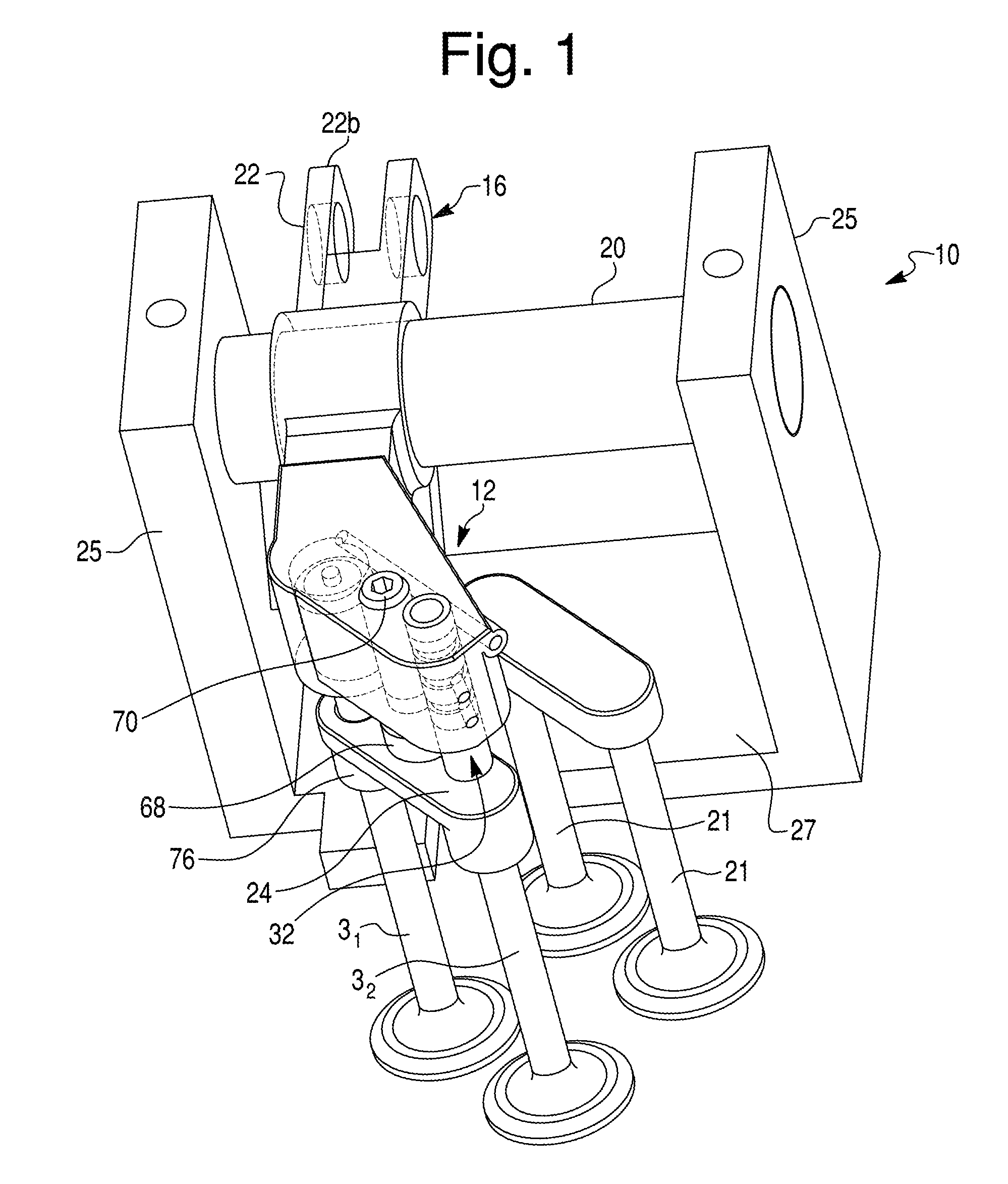
This application claims the benefit of provisional applications No. 61/908,272 filed on Nov. 25, 2013 by V. Meneely and R. Price, and of No. 62/001,392 filed on May 21, 2014 by V. Meneely and R. Price, which are hereby incorporated herein by reference in their entirety and to which priority is claimed. 1. Field of the Invention The present invention relates to compression-release engine brake systems in general, and more particularly to a compression-release engine brake system and method comprising a lost motion type engine brake rocker arm assembly incorporating structure implementing a valve reset function. 2. Description of the Related Art Compression release engine brake systems (or retarders) for diesel engines were designed and developed in North America starting in the early 1960's. There have been many changes that have been implemented that have increased retarding performance, reduced cost, reduced engine loading and reduced engine valve train loading. Conventionally, the engine brake compression release retarders change a power producing diesel engine to a power absorbing air compressor. The air in the cylinder is compressed on the compression stroke and is released near top dead center (TDC) just prior to the expansion stroke to reduce the cylinder pressure and prevent it from pushing the piston down on the expansion stroke. In the so-called exhaust brake systems, work on the air is done on the exhaust stroke when the piston is moving up and there is a pressure increase in the exhaust manifold from turbocharger restriction or an exhaust restriction. The opening of the exhaust valve(s) near TDC to vacate cylinder pressure can be accomplished by a number of different approaches. Some of the most common methods used are add-on housings that hydraulically transfer intake or exhaust cam motion from a neighboring cylinder, or fuel injector motion from the same cylinder to provide a method of timing the exhaust valve(s) to open near TDC compression stroke to optimize the release of compressed air in the cylinder. Other engine brake systems have a rocker arm brake that utilizes an exhaust rocker arm (or lever) to open the exhaust valve(s) near TDC compression stroke. A term used to identify a type of rocker arm brake is a lost motion concept. This concept adds an additional small lift profile to the exhaust cam lobe that opens the exhaust valve(s) near TDC compression stroke when excess exhaust valve lash is removed from the valve train. Rocker arm brake systems using the lost motion principle have been known for many years. One problem with the conventional rocker arm brake system is that valve overlap at exhaust/intake is extended and thus braking performance decreased. Moreover, a problem with opening a single valve is that exhaust/intake overlap is extended and the opening up an exhaust bridge is unbalanced during the initial normal exhaust lift and might result in engine overhead damage. Extended overlap allows exhaust gas to flow backwards into the engine from the exhaust manifold and through the inlet valve into the inlet manifold. In other words, the extended valve overlap causes an undesired exhaust manifold air mass flow into the engine intake system, thus reducing exhaust stroke work and decreasing braking performance. We disclose a system to open the exhaust valve(s) as late as possible, open the exhaust valves the maximum amount at a faster rate, and evacuating the cylinder quickly to provide a very high performance engine brake. There are a number of engine parameters that restrict the optimum valve opening. These limitations include valve train loading, engine design limits, emissions regulations and other considerations. According to a first aspect of the invention, a compression-release brake system is configured to operate at least one exhaust valve of an internal combustion engine. The compression-release brake system of the present invention operates in a brake-on mode during a compression-release engine braking operation and a brake-off mode during a positive power operation. The compression-release brake system maintains the at least one exhaust valve open during a portion of a compression stroke of the engine when performing the compression-release engine braking operation. The compression-release brake system comprises an exhaust rocker assembly for operating the at least one exhaust valve. The exhaust rocker assembly includes an exhaust rocker arm mounted about a rocker shaft and selectively pivotable to open the at least one exhaust valve. The compression-release brake system further comprises an actuation piston moveable between retracted and extended positions and slidably disposed in an actuation piston bore formed in said exhaust rocker arm. The actuation piston is operatively coupled to the at least one exhaust valve when in the extended position. The actuation piston defines an actuation piston cavity within the actuation piston bore between the actuation piston bore and the actuation piston. The compression-release brake system further comprises a supply conduit formed within the exhaust rocker arm. The supply conduit is configured to supply pressurized hydraulic fluid to the actuation piston cavity to displace the actuation piston to the extended position when there is a gap between the actuation piston and the at least one exhaust valve. The compression-release brake system further comprises an exhaust valve reset device mounted to the exhaust rocker arm. The exhaust valve reset device includes a reset check valve disposed between the supply conduit and the actuation piston cavity to hydraulically lock the actuation piston cavity by closing the reset check valve when pressure of the hydraulic fluid within the actuation piston cavity exceeds the pressure of the hydraulic fluid in the supply conduit. The reset check valve is biased closed by the pressure of the hydraulic fluid within the actuation piston cavity during the brake-on mode. According to a second aspect of the invention, there is provided a method of operating a compression-release brake system in a brake-on mode for operating at least one exhaust valve of an internal combustion engine during a portion of a compression-release engine braking operation. The compression-release brake system maintains the at least one exhaust valve open during a compression stroke of the engine when performing the compression-release engine braking operation. The compression-release brake system comprises an exhaust rocker assembly for operating the at least one exhaust valve. The exhaust rocker assembly includes an exhaust rocker arm mounted about a rocker shaft and selectively pivotable to open the at least one exhaust valve. The compression-release brake system further comprises an actuation piston moveable between retracted and extended positions and slidably disposed in an actuation piston bore formed in said exhaust rocker arm. The actuation piston is operatively coupled to the at least one exhaust valve when in the extended position. The actuation piston defines an actuation piston cavity within the actuation piston bore between the actuation piston bore and the actuation piston. The compression-release brake system further comprises a supply conduit formed within the exhaust rocker arm. The supply conduit is configured to supply pressurized hydraulic fluid to the actuation piston cavity to displace the actuation piston to the extended position when there is a gap between the actuation piston and the at least one exhaust valve. The compression-release brake system further comprises an exhaust valve reset device mounted to the exhaust rocker arm. The exhaust valve reset device includes a reset check valve disposed between the supply conduit and the actuation piston cavity to hydraulically lock the actuation piston cavity by closing the reset check valve when pressure of the hydraulic fluid within the actuation piston cavity exceeds the pressure of the hydraulic fluid in the supply conduit. The reset check valve is biased by the pressure of the hydraulic fluid within the actuation piston cavity during the brake-on mode. The reset check valve is biased closed by the pressure of the hydraulic fluid within the actuation piston cavity during part of the brake-on mode. The method comprises the steps of mechanically biasing the reset check valve closed during a first part of a valve brake lift of the at least one exhaust valve during a compression stroke of the internal combustion engine, hydraulically biasing the reset check valve closed during a second part of a valve brake lift of the at least one exhaust valve, and resetting the at least one exhaust valve during an expansion stroke of the engine by opening the reset check valve and releasing hydraulic fluid from the actuation piston cavity to close the at least one exhaust valve. The compression-release brake system of the present invention is low cost and can be integrated into the overall engine design. Moreover, the present invention provides a compression-release brake system that is lightweight, does not mechanically and thermally overload the engine system, has quiet operation and yields optimum retarding power over the entire engine speed range where the engine brake is used. The accompanying drawings are incorporated in and constitute a part of the specification. The drawings, together with the general description given above and the detailed description of the exemplary embodiments and methods given below, serve to explain the principles of the invention. In these drawings: Reference will now be made in detail to exemplary embodiments and methods of the invention as illustrated in the accompanying drawings, in which like reference characters designate like or corresponding parts throughout the drawings. It should be noted, however, that the invention in its broader aspects is not limited to the specific details, representative devices and methods, and illustrative examples shown and described in connection with the exemplary embodiments and methods. This description of exemplary embodiments is intended to be read in connection with the accompanying drawings, which are to be considered part of the entire written description. In the description, relative terms such as “horizontal,” “vertical,” “front,” “rear,” “upper”, “lower”, “top” and “bottom” as well as derivatives thereof (e.g., “horizontally,” “downwardly,” “upwardly,” etc.) should be construed to refer to the orientation as then described or as shown in the drawing figure under discussion and to the orientation relative to a vehicle body. These relative terms are for convenience of description and normally are not intended to require a particular orientation. Terms concerning attachments, coupling and the like, such as “connected” and “interconnected,” refer to a relationship wherein structures are secured or attached to one another either directly or indirectly through intervening structures, as well as both movable or rigid attachments or relationships, unless expressly described otherwise. The term “operatively connected” is such an attachment, coupling or connection that allows the pertinent structures to operate as intended by virtue of that relationship. Additionally, the words “a” and/or “an” as used in the claims mean “at least one”. In summary, embodiments disclosed herein utilize a reset mechanism carried by or integrated into an engine rocker arm which actuates one of two exhaust valves. The exhaust valve reset device eliminates the opening of an unbalanced exhaust valve bridge and additionally minimizes exhaust/intake valve overlap near the start of the intake stroke. Actuating one of two exhaust valves results in reducing valve train loading and provides the ability to delay exhaust valve opening resulting in increased charge for better braking performance. The reduced valve overlap increases exhaust manifold back pressure by reducing the exhaust manifold air mass from flowing back into the intake manifold. The increased exhaust stroke pressure creates additional engine work by the engine brake during the exhaust stroke. Extended valve overlap causes an undesired exhaust manifold air mass flow into the engine intake system, thus reducing exhaust stroke work and decreasing braking performance. During brake operation, a reset check valve in the reset device is hydraulically locked due to the increasing cylinder pressure during the compression stroke. As the cylinder pressure drops after top dead center of the compression stroke, the hydraulic pressure applied to the reset check valve begins to correspondingly fall. Eventually the hydraulic pressure drops sufficiently so that a biasing force applied to the reset check valve overcomes the hydraulic force and the reset check valve opens and allows engine oil to flow and thus resets the exhaust valve and allows both exhaust valves to move during the exhaust cycle. The rocker arm compression-release engine brake system 12 according to the exemplary embodiment of the present invention is a lost motion engine brake system that, as best shown in The rocker arm compression-release engine brake system 12 according to the first exemplary embodiment of the present invention includes a conventional intake rocker assembly (not shown) for operating two intake valves 1, and a lost motion exhaust rocker assembly 16 for operating the exhaust valve(s). The exhaust rocker assembly 16 according to the first exemplary embodiment of the present invention is of a lost motion type provided with automatic hydraulic adjusting and resetting functions. The exhaust rocker assembly 16 includes an exhaust rocker arm 22 pivotally mounted about a rocker shaft 20 and provided to open first and second exhaust valves 31and 32, respectively, through an exhaust valve bridge 24. The rocker shaft 20 is supported by rocker arm supports (or rocker arm pedestals) 25 and extends through a rocker arm bore 33 formed in the exhaust rocker arm 22 (as best shown in The exhaust rocker arm 22, as best shown in The driven end 22 Moreover, the exhaust rocker arm 22 also includes a rocker arm adjusting screw assembly 68 (as best shown in The adjustment screw 70 is provided with a hexagonal socket 71 accessible from above the exhaust rocker arm 22 for setting a predetermined valve lash (or clearance) δ between the contacting foot 72 of the adjusting screw 68 and the exhaust valve bridge 24 when the exhaust rocker roller follower 21 is in contact with a lower base circle 5 on the exhaust cam 2, i.e., when the exhaust cam 2 is not acting (pressing) on the exhaust rocker arm 22. The predetermined valve lash δ is set to provide a normal exhaust valve motion in a positive power operation with clearance for valve train component growth at engine operating temperatures. In an engine brake operation all lash (except the predetermined valve lash δ) is removed from the valve train and the brake cam profile determines the opening timing, profile and lift of the exhaust valves. The lost motion engine brake rocker arm assembly 16 is part of the rocker arm compression-release engine brake system 12 provided for the internal combustion (IC) engine. Pressurized hydraulic fluid, such as engine oil, is supplied to the exhaust rocker arm 22 under high pressure through a high pressure hydraulic circuit, as best illustrated in The exhaust rocker arm 22 further includes a substantially cylindrical actuation piston bore 64 (best shown in The actuation piston 62 defines an actuation (or reset) piston cavity 65 within the actuation piston bore 64 in the exhaust rocker arm 22 (best shown in Moreover, the semi-spherical bottom surface 63 The rocker arm compression-release brake system 12 further comprises an exhaust valve reset device 32 disposed in the exhaust rocker arm 22. The reset device 32 according to the first exemplary embodiment of the present invention (shown in detail Each of the supply groove 36, the brake-on groove 38 and the piston groove 40 are formed on an outer peripheral cylindrical surface of the cartridge body 34 and axially spaced from each other. Moreover, the supply groove 36 is provided with at least one continuous supply port 37 through the cartridge body 34, the brake-on groove 38 is provided with at least one brake-on supply port 39 through the cartridge body 34, while the piston groove 40 is provided with at least one piston supply port 41 through the cartridge body 34. The cylindrical cartridge body 34 is non-movably disposed within a substantially cylindrical reset bore 23 The reset device 32, as best shown in The exhaust valve reset device 32 further comprises a reset trigger 50 axially slidable within the cartridge body 34. The reset trigger 50 has an elongated distal end 52 at least partially extending from the cartridge body 34 through a bore 35 The trigger return spring 56 biases the reset trigger 50 upward to a counter-bore stop 35 As best illustrated in As further illustrated in Specifically, the stop portion 5521of the spring retainer 552defines a mechanical stop activated by exceeding addition upward stroke of the reset trigger 50 than normal maximum stroke of the reset trigger 50. This additional stroke of the reset trigger 50 would occur should the pressure spring 57 fail and do not force the ball check 44 off its seat 45 and the single engine brake exhaust valve 31does not reset prior to normal exhaust valve lift with a balanced bridge. The additional stroke of the elephant foot 722pressing on a center of the exhaust valve bridge 242results in a small unbalance of the exhaust valve bridge 242until the addition of the trigger stroke resulting from the rocker rotation during the normal exhaust valve motion forces the stop portion 5521of the spring retainer 552to contact the internal stop portion 50 The rocker shaft 20 according the exemplary embodiment of the present invention, shown in As further shown in In operation, the pressurized hydraulic fluid is supplied to the accumulator cavity 94 through the supply passage 93 and the accumulator ball-check valve 92. Then, the pressurized hydraulic fluid flows from the accumulator cavity 94 to the continuous supply conduit 26 of the exhaust rocker arm 22 through the connecting port 96, the connecting passage 97 and the supply port 95. During engine braking reset operation, the pressurized hydraulic fluid is dumped back into the rocker shaft accumulator cavity 94. The accumulator ball-check valve 92 prevents hydraulic fluid flow back into the hydraulic fluid supply passage 93. The rocker arm compression-release brake system 12 further comprises an on-off solenoid valve 98, shown in The positive power operation of the engine is as follows. During the positive power operation, when the engine brake is not activated, the hydraulic fluid continuous supply conduit 26 provides continuous flow of hydraulic fluid, such as motor oil, to the check-valve cavity 421through the continuous supply groove 36 and the continuous supply port 37. Moreover, during the positive power operation, the reset trigger 50 is in the retracted position by the biasing force of the trigger return spring 56. In this position, the ball-valve member 44 is lifted off the check-ball seat 45 (to an open position of the reset check valve 43) by the reset trigger 50. Specifically, the reset trigger 50 lifts, through the resilient biasing action of the trigger return spring 56 and the upset pin 58, which contacts, lifts and holds the ball-valve member 44 off the check-ball seat 45 for all non-engine brake operation. As the reset check valve 43 is open, the pressurized hydraulic fluid flows past the check valve 43 from the check-valve cavity 421through the piston supply port 41 and into the high-pressure conduit 28. Then, the pressurized hydraulic fluid flows through the high-pressure conduit 28 into the actuation piston bore 64. The pressurized hydraulic fluid completely fills the actuation piston cavity 65, thus eliminating the valve train lash (except the predetermined valve lash δ), such as actuation piston lash, i.e., lash between the actuation piston 62 and the single-valve actuation pin 76. The increase in the volume of the hydraulic fluid in the actuation piston cavity 65 also allows the exhaust rocker roller follower 21 to maintain contact with the exhaust camshaft brake lift profile 7 and with the added displacement created by the actuation piston 62, eliminates the brake lift and provides a normal exhaust valve profile for the exhaust stroke marked in In the engine brake-off mode, with the valve train lash eliminated (except the predetermined valve lash δ), the exhaust rocker arm 22 then proceeds from the lower base circle 5 on the exhaust cam 2 to the engine brake lift profile 7. When the engine brake lift profile 7 acts on the driven end 22 During the exhaust stroke of the positive power operation, when the exhaust cam profile 6 acts on the driven end 22 When the engine brake is not activated (brake-off mode) and the exhaust cam is on the lower base circle 5, the actuation piston 62 extends in the actuation piston bore 64 in the exhaust rocker arm 22 to remove all valve train lash (except the predetermined valve lash δ). The engine brake profile 7 of the exhaust cam 2 cannot open the exhaust valve 31for compression release braking since the reset check valve 43 is held open by the upset pin 58. The hydraulic fluid flows out of the actuation piston cavity 65 and into the rocker shaft accumulator 77 located in the rocker shaft 20 (as shown in During the brake-on mode, the solenoid valve 98 is energized, allowing the brake-on pressurized hydraulic fluid to be supplied to the brake-on supply conduit 30. The pressurized hydraulic fluid from the brake-on supply conduit 30 enters the reset cavity 422in the cartridge body 34 of the exhaust valve reset device 32. The pressurized hydraulic fluid in the reset cavity 422overcomes the biasing force of the trigger return spring 56 and moves the reset trigger 50 to the extended position. In this position, as best shown in The engine braking operation is described hereafter. The rocker shaft 20 that supplies the pressurized hydraulic fluid is designed with two passageways 97 and 99 to supply the pressurized hydraulic fluid to the continuous supply conduit 26 and the brake-on supply conduit 30, respectively, of the engine brake rocker arm assembly 16. The brake-on supply conduit 30 is controlled by the solenoid valve 98 that supplies the pressurized hydraulic fluid to the brake-on supply conduit 30, which displaces the reset trigger 50 downwardly allowing the reset check valve 43 to seat (i.e., in the closed position) and functions as a check valve to lock the hydraulic fluid in the high-pressure conduit 28 and the actuation piston cavity 65. The hydraulic pressure within the actuation piston cavity 65 assures that all lash is removed (including the actuation piston lash) from the valve train assembly (except the predetermined valve lash δ) and the exhaust rocker roller follower 21 of the exhaust rocker arm 22 is kept in contact with the exhaust cam 2. To start the engine brake-on mode, the solenoid valve 98 is energized to flow oil through the brake-on oil supply conduit 30 to the reset cavity 422to bias the reset trigger 50 downward and provide a clearance between the ball-valve member 44 and the upset pin 58 allowing the ball-check spring 46 to bias the ball-valve member 44 against the check-ball seat 45. The pressurized engine oil is supplied to the rocker arm continuous supply port 37 through the reset check valve 43 and the high-pressure conduit 28 and into the actuation piston cavity 65, removing all valve train lash between the single-valve actuation pin 76 and the actuation piston 62, and the cam follower 21 and the lobe of the exhaust cam 2. With all valve train lash eliminated (except the predetermined valve lash δ) and the hydraulic fluid locked in the actuation piston cavity 65, the roller follower 21 proceeds from the lower base circle 5 on the exhaust cam 2 to the engine brake lift profile 7 to open only the exhaust valve 31through the single-valve actuation pin 76 just prior to a Top Dead Center (TDC) in the compression stroke to evacuate the highly compressed air in the cylinder resulting from the compression stroke. When the engine brake lift profile 7 acts on the driven end 22 With all the valve train lash (except the predetermined valve lash δ) removed and hydraulically locked, the brake lift profile 7 of the exhaust cam member 2 opens only the first exhaust valve 31just prior to TDC of the compression stroke during the compression-release engine braking event, as illustrated by a portion 881of the exhaust valve lift profile 85 in FIG. 12. Due to the predetermined valve lash δ, the adjusting screw 68 does not press against the exhaust valve bridge 24. Thus, the second exhaust valve 32remains closed throughout the compression-release engine braking event of the engine compression brake operation. During the opening of the single exhaust valve 31with the single-valve actuation pin 76, the cylinder pressure is increasing and rapidly reaches peak cylinder pressure just prior to TDC compression, then cylinder pressure drops rapidly just after TDC compression. Because of the compression release near TDC and the engine piston in the cylinder moving downward in the engine cylinder, the cylinder pressure is decreasing rapidly and so does the pressure in the actuation piston cavity 65, resulting in lower pressure biasing the ball-valve member 44 against the check-ball seat 45. During the compression-release engine braking event during the power stroke, a process of resetting the exhaust valve 31is accomplished by the elongated distal end 52 of the reset trigger 50 coming in contact with a top surface 24 Upon the contact of the elongated distal end 52 of the reset trigger 50 with the exhaust valve bridge 24, as the driving end 22 In other words, reset occurs when the reset trigger 50 is forced upward by rotation of the exhaust rocker arm 22 causing the reset pressure spring 57 to be compressed and apply a high force to the ball-valve member 44 of the check valve 43 that is initially not capable of moving the ball off its seat 45 until cylinder pressure and pressure in the actuation piston cavity 65 is reduced to the point that the reset pressure spring 57 will force the ball-valve member 44 off its seat 45. This occurs at the end of the expansion stroke 89 when cylinder pressure is low. Opening of the check valve 43 results in releasing a portion of the hydraulic fluid from the actuation piston cavity 65, i.e., allowing the pressurized hydraulic fluid in the actuation piston cavity 65 to return to the continuous supply conduit 26 in the exhaust rocker arm 22. This causes the actuation piston 62 and the single-valve actuation pin 76 to move upward, thus permitting the single exhaust valve 31to be reset and return the first exhaust valve 31back to its valve seat. During engine brake operation of the engine without the exhaust valve reset device 32, with all valve train lash removed (except the predetermined valve lash δ), a normal exhaust valve lift profile 14 will be increased in a lift 15 and duration, as shown in During engine brake operation of the engine with the exhaust valve reset device 32 (shown at 88 in As illustrated in Make-up hydraulic fluid to refurbish the reset hydraulic fluid is supplied from the rocker shaft accumulator 77 that, according to the exemplary embodiment of the present invention, is located in the rocker arm shaft 20. Alternatively, the rocker shaft accumulator 77 can be located in the rocker arm shaft support. This accumulated hydraulic fluid will be stored in the rocker shaft accumulator 77 at close proximity and at a higher pressure to assist in completely filling the actuating piston cavity 65 and the high-pressure conduit 28 for the next pre-charge lift profile 8 or the engine brake exhaust lift profile 7. The pre-charge lift profile 8 of the exhaust cam lobe 2 opens the first exhaust valve 31near the end of the intake stroke. This adds a high pressure air charge and additional boost from the exhaust manifold into the cylinder at the start of the exhaust stroke to enable more work to be done on the air during the compression stroke and potentially on the exhaust stroke and, depending on high exhaust manifold backpressure, could produce a reduced engine brake exhaust sound level. Therefore, the lost motion rocker arm compression-release engine brake system according to the first exemplary embodiment of the present invention opens only one of two exhaust valves during the engine compression release event and resets the one exhaust valve prior to the normal exhaust stroke valve motion. In the first exemplary embodiment of the present invention, the engine compression release single exhaust valve lift opening is approximately 0.100 inches and the lift starts just prior to TDC compression stroke. Contemporary diesel engines are usually equipped with an exhaust valve bridge and two exhaust valves. A reset device according to the present invention is desirable to close the single braking exhaust valve prior to the opening of both exhaust valves during the normal exhaust stroke, so that the exhaust valve bridge is not in an unbalanced condition. An unbalanced condition is where the single-valve actuation pin has not returned the single braking exhaust valve to the seated position resulting in an unbalanced force on the bridge during normal exhaust valve opening. The reset device 32, according to the first exemplary embodiment of the present invention, is located further away from a center of rotation of the exhaust rocker arm 22 (or the rocker arm shaft 20) than a center of the exhaust valve bridge 24 and the adjusting screw 68 to provide the maximum trigger motion to allow the reset trigger 50 to move upward in the cartridge body 34 removing lash between the ball-valve member 44 and the upset pin 58, and to provide compression of the reset pressure spring 57. Compression release cylinder pressure results in biasing the reset check valve 43 closed, by the high hydraulic circuit pressure. During the beginning of the expansion stroke, the cylinder pressure decreases rapidly to a value that the reset pressure spring 57 that is being compressed can lift the ball-valve member 44 off the seat 45 thereof. At the time when the ball-valve member 44 is forced off its seat 45, the hydraulic fluid in the actuation piston cavity 65 will be released, thereby resetting the single engine brake exhaust valve 31. The resetting function occurs prior to the normal exhaust stroke, resulting in both exhaust valves 31and 32being seated and the exhaust valve bridge 24 can now be opened by the exhaust rocker arm 22 with the exhaust bridge 24 in a balanced condition. Present lost motion rocker brakes are commercially available without resetting and are accomplished by incorporating increased strength bridge guide pins to solve the unbalanced bridge loading problem. The prior art approach is more costly and provides less retarding performance because of the extended intake/exhaust valve overlap condition. Extended intake/exhaust valve overlap results in the loss of exhaust manifold air mass and pressure back into the cylinder and inlet manifold. The loss of exhaust manifold pressure decreases engine brake retarding performance. The single valve rocker arm lost motion compression-release engine brake system with reset, according to the present invention, reduces cost of a conventional engine brake system or even a dedicated cam brake. The rocker arm compression-release engine brake system of the present invention provides better performance than an exhaust cam driven brake or even an injector driven one. The performance of the single valve rocker arm compression-release engine brake system of the present invention compared to a dedicated cam engine brake in most circumstances will be close. Compared to other engine brake configurations, the single valve rocker arm lost motion compression-release engine brake system with reset is better in weight, cost of development, requirements to make fundamental changes to existing engines, engine height and manufacturing cost per engine. The valve train assembly 110 includes a rocker arm compression-release engine brake system 112 according to the second exemplary embodiment of the present invention, provided for an internal combustion (IC) engine. Preferably, the IC engine is a four-stroke diesel engine. As illustrated in The exhaust rocker assembly 116 according to the second exemplary embodiment of the present invention is a lost motion type provided with automatic hydraulic adjusting and resetting functions. The exhaust rocker assembly 116 includes an exhaust rocker arm 122 pivotally mounted about a rocker shaft 20 and provided to open first and second exhaust valves 31and 32, respectively, through an exhaust valve bridge 24. The rocker shaft 20 is supported by rocker arm supports (or rocker arm pedestals) 25 and extends through a rocker arm bore 133 formed in the exhaust rocker arm 122 (shown in The rocker arm compression-release brake system 112 further comprises an exhaust valve reset device 132 disposed in the exhaust rocker arm 122. The exhaust valve reset device 132 according to the second exemplary embodiment of the present invention is substantially structurally and functionally identical to the exhaust valve reset device 32 of the first exemplary embodiment of the present invention (shown in detail As best illustrated in Alternatively, an outer peripheral cylindrical surface 149 of a cartridge body 134′ of an alternative embodiment of an exhaust valve reset device, generally depicted with the reference numeral 132′, is wholly or at least partially threaded as best illustrated in An upper cartridge plug 135 The valve train assembly 310 includes a rocker arm compression-release engine brake system 312. Preferably, the IC engine is a four-stroke diesel engine, comprising a cylinder block including a plurality of cylinders. The rocker arm compression-release engine brake system 312 includes a conventional intake rocker assembly (not shown) for operating two intake valves 1, and a lost motion exhaust rocker assembly 316 for operating first and second exhaust valves 31and 32. The exhaust rocker assembly 316 according to the third exemplary embodiment of the present invention is of a lost motion type provided with automatic hydraulic adjusting and resetting functions. The exhaust rocker assembly 316 includes an exhaust rocker arm 322 pivotally mounted about a rocker shaft 20 and provided to open the first and second exhaust valves 31and 32, respectively, through an exhaust valve bridge 24. The rocker shaft 20 is supported by rocker arm supports (or rocker arm pedestals) and extends through a rocker arm bore 333 formed in the exhaust rocker arm 322 (shown in The rocker arm compression-release brake system 312 further comprises an exhaust valve reset device 332 disposed in the exhaust rocker arm 322 in the direction substantially parallel to the exhaust valves 31and 32. The exhaust valve reset device (or spool cartridge) 332 according to the third exemplary embodiment of the present invention, as best illustrated in The reset device 332 further comprises a substantially cylindrical reset spool 340 axially slidingly disposed within the cylindrical cartridge body 334. The reset spool 340 is movable within and relative to the cartridge body 334 between a refracted position shown in As further illustrated in The reset spool 340 is further formed with a second annular spool recess 354 between the inner peripheral surface 335 of the cartridge body 334 and the outer peripheral surface 347 of the reset spool 340. The second annular recess 354 defines an upper spool cavity and is in fluid communication with the check-valve cavity 3421through at least one second communication port 355 in the reset spool 340. As best illustrated in The reset device 332 further comprises a ball-valve member 344, and a ball-check spring 346 disposed between the ball-valve member 344 and the upper cartridge plug 335. The ball-valve member 344 is held on a check-ball seat 345 by a biasing spring force of the ball-check spring 346 so as to close a communication port 348 in the reset spool 340, which fluidly connects the continuous pressure supply port 337 of the cartridge body 334 and the check-valve cavity 3421of the reset spool 340. The ball-valve member 344, the check-ball seat 345 and the ball-check spring 346 define a reset check valve 343. The check valve 343 provides selective fluid communication between the continuous supply conduit 26 and the high-pressure conduit 28 (i.e., between the continuous supply conduit 26 and the actuation piston cavity 65) through the second communication ports 355. It will be appreciated that any appropriate type of the check valve is within the scope of the present invention. The continuous pressure supply port 337 and the piston supply port 341 are formed on an outer peripheral cylindrical surface of the cartridge body 334 and axially spaced from each other. The threaded cylindrical cartridge body 334 is adjustably disposed within the substantially cylindrical reset bore in the exhaust rocker arm 322. The exhaust valve reset device 332 further comprises a reset trigger 350 axially slidable within the reset cavity 3422of the reset spool 340. The reset trigger 350 has a semi-spherical distal end 352 at least partially extending from the cartridge body 334. The reset trigger 350 is movable relative to the cartridge body 334 between a retracted position shown in The valve train assembly 310 according to the third exemplary embodiment of the present invention further comprises a compression release actuator 376 provided to selectively move the reset spool 340 between the retracted position shown in The compression-release brake system 312 operates in a compression brake mode, or brake-on mode (during the engine compression brake operation) and a compression brake deactivation mode, or brake-off mode (during the positive power operation). In operation of the engine with the rocker arm compression-release engine brake system 312 with the reset device 332 according to the third exemplary embodiment of the present invention, during the brake-off mode the compression release actuator 376 is deactivated and the brake-on piston 380 is in a retracted position so that the brake-on piston 380 is axially spaced from the reset spool 340 of the reset device 332, as illustrated in Accordingly, during the brake-off mode, the pressurized fluid is continuously supplied from the continuous supply conduit 26 to the actuation piston cavity 65 through the lower spool cavity 351 and the piston supply port 341 of the reset device 332, and the high-pressure passageway 28, as shown in The engine braking operation during the brake-on mode is as follows. To activate the engine brake, the compression release actuator 376 is activated and the brake-on piston 380 moves into an extended position, shown in During the engine compression stroke the biasing forces of the brake-on piston 380 of the compression release actuator 376 and hydraulic pressure in the upper spool cavity 354 bias the reset spool 340 in the extended position thereof. On the other hand, the reset pressure spring 357 and the trigger return spring 356 bias the reset spool 340 in the retracted position. As the cylinder pressure continues to increase, the hydraulic pressure in the upper spool cavity 354 also increases, creating a larger biasing force to maintain the reset spool 340 in the downward, extended position and continuing to lock the hydraulic fluid in the actuation piston cavity 65 above the single valve actuation piston 62. When the engine stroke changes from the compression stroke to the expansion stroke, the cylinder pressure decreases rapidly to approximately atmospheric pressure. When the pressure in the piston supply port 341 and the upper spool cavity 354 decreases to approximately 250 psi pressure, any significant hydraulic biasing force on the reset spool 340 is eliminated, resulting in the upward biasing force of the reset pressure spring 357 exceeding the downward biasing force of the compression release actuator 376. As a result, the reset spool 340 transitions upward to open the piston supply port 341 to the lower spool cavity 351, thus unlocking the actuation piston 62, i.e., allowing the hydraulic fluid from the actuation piston cavity 65 to flow back into the continuous oil supply conduit 126 through the continuous pressure supply port 337. This oil flow through the continuous pressure supply port 337 allows the single exhaust valve 31to be reseated and completes single valve reset function. The reset pressure spring 357 has a spring rate such as to generate an adequate force to be able to overcome the force of approximately 100 pounds from the valve spring 91of the braking exhaust valve 31hat creates the pressure differential across the reset ball-valve member 444 of the reset check valve 443 at the end of the expansion stroke to reset the single exhaust valve 31. The valve train assembly 410 includes a rocker arm compression-release engine brake system 412. Preferably, the IC engine is a four-stroke diesel engine, comprising a cylinder block including a plurality of cylinders. The rocker arm compression-release engine brake system 412 comprises a conventional intake rocker assembly (not shown) for operating two intake valves 1, and a lost motion exhaust rocker assembly 416 for operating first (or braking) and second exhaust valves 31and 32, respectively. The exhaust rocker assembly 416 according to the fourth exemplary embodiment of the present invention is a lost motion type provided with automatic hydraulic adjusting and resetting functions. The exhaust rocker assembly 416 includes an exhaust rocker arm 422 pivotally mounted about a rocker shaft 20 and provided to open the first and second exhaust valves 31and 32, respectively, through an exhaust valve bridge 24. The rocker shaft 20 is supported by rocker arm supports (or rocker arm pedestals) and extends through a rocker arm bore 433 formed in the exhaust rocker arm 422 (shown in The IC engine incorporating the compression-release brake system 412 in accordance with the fourth exemplary embodiment of the present invention includes a pushrod (shown in The rocker arm brake system 412 also comprises a substantially cylindrical actuation piston bore 464 formed in the exhaust rocker arm 422 for slidably receiving an actuation piston 462 (best shown in The rocker arm brake system 412 further comprises an exhaust valve reset device 432 disposed in the exhaust rocker arm 422. The exhaust valve reset device 432 includes a reset check valve disposed in the actuation piston 462, as shown in The ball-valve member 444 is biased open, i.e., held away from the check-ball seat 445 by a biasing spring force of the reset spring 446, so as to open a communication port 448 in the actuation piston 462, which fluidly connects the reset piston cavity 465 with a communication conduit 453 formed through the actuation piston 462. In turn, the communication conduit 453 in the actuation piston 462 is fluidly connected directly to the continuous supply conduit 426. In other words, when the reset check valve 443 is open, the continuous supply conduit 426 is fluidly connected to the reset piston cavity 465. The exhaust valve reset device 432 of the rocker arm brake system 412 further includes a rocker check valve 450 also disposed in the exhaust rocker arm 422. In the exemplary embodiment of the present invention, the rocker check valve 450 is in the form of a ball-check valve, which is normally biased closed. It will be appreciated that any appropriate type of the check valve, other than the ball-check valve, is also within the scope of the present invention. The rocker check valve 450 is disposed in a check-valve bore 434 formed in the exhaust rocker arm 422 substantially perpendicular to the rocker arm bore 433 receiving the rocker shaft 20. The bore 434 is closed by a plug 435. The rocker check valve 450 comprises a ball-valve member 440 disposed in the check-valve bore 434, and a ball-check spring 442 biasing the all-valve member 440 to closing position thereof. In other words, the ball-valve member 440 is held on a check-ball seat by a biasing spring force of the ball check spring 442 so as to close a communication opening 452 through the rocker check valve 450, which fluidly connects the continuous supply conduit 426 and the reset piston cavity 465 through a reset conduit 428. The rocker arm brake system 412 according to the fourth exemplary embodiment of the present invention further comprises a compression release actuator 476 provided to selectively control the exhaust valve reset device 432. The compression release actuator 476, shown in The rocker arm brake system 412 according to the fourth exemplary embodiment of the present invention further comprises a reset pin 458 extending between the brake-on piston 480 and the reset ball-valve member 444 of the reset check valve 443. Moreover, the exhaust rocker arm 422 includes a rocker arm adjusting screw assembly 468 (as best shown in As best illustrated in The screw assembly 468 comprises an adjustment screw 470 having a ball-like end 471 for being received in a socket (not shown) coupled to a top end of the pushrod. The adjustment screw 470 is adjustably, such as threadedly, mounted in the driven end 422 The compression-release brake system 412 operates in a compression brake mode, or brake-on mode (during the engine compression brake operation) and a compression brake deactivation mode, or brake-off mode (during the positive power operation). The engine braking operation during the brake-on mode is as follows. To activate the engine brake, the compression release actuator 476 is activated and the pressurized fluid enters the brake-on piston cavity 481 through the brake-on fluid supply port 482. Pneumatic or hydraulic fluid, such as engine oil, supplied to the brake-on piston cavity 481, forces the brake-on piston 480 downward. Subsequently, the brake-on piston 480 moves into an extended position thereof so as to engage and move downward the piston stroke limiting pin 484, shown in The operation of the compression-release engine brake system 412 according to the fourth exemplary embodiment requires opening only one of the two exhaust valves 31and 32so not to exceed the valve train maximum valve train loading specifications. The opening of the braking exhaust valve 31incorporates a single valve brake lift of approximately 0.100 inches. The compression-release engine brake system 412 requires the brake-on piston 480 to provide a substantial downward biasing force to the ball-valve member 444 of the reset check valve 443 via the reset pin 458 to seal (i.e., close) the reset check valve 443 for approximately 50% of the typical 0.100 inch lift of the braking exhaust valve 31for the initial valve opening. In other words, the ball-valve member 444 is biased closed mechanically in the first 0.050 inches of the single valve brake lift. When the lift of the braking exhaust valve 31is at approximately 50% (or 0.050 inches) of its entire engine brake braking lift, the brake-on piston 480 engages the adjustable piston stroke limiting pin (or positive stop) 484. From that moment on the downward linear movement of the brake-on piston 480 is prevented. Subsequently, as the exhaust rocker arm 422 continues to move the exhaust bridge 24 downward, the brake-on piston 480 stops pushing the reset pin 458 downward. Cylinder pressure and, therefore, the valve force against the actuation piston 462 continues to rise during the second half of the motion of the braking exhaust valve 31. The increasing hydraulic pressure now holds the reset ball-valve member 444 firmly on its seat 445, such that contact with the reset pin 458 is no longer needed for the last (or second) 50% of motion. In other words, the downward biasing force of the reset pin 458 on the ball-valve member 444 is eliminated at approximately 50% of the opening of the braking exhaust valve 31resulting from the contact of the brake-on piston 480 with the adjustable positive stop 484, as the exhaust rocker arm 422 continues to open the braking exhaust valve 31. Cylinder pressure continues to increasing during the compression stroke, thus biasing the braking exhaust valve 31upward and increasing the pressure of the oil in the reset piston cavity 465. As a result, the downward biasing force acting to the reset ball-valve member 444 is provided. The high pressure in the reset piston cavity 465 produces a high pressure differential across the reset ball-valve member 444 to continue to bias the reset ball-valve member 444 seated, i.e., to the closed position of the reset check valve 443. In other words, the pressure in the actuation piston cavity 465 hydraulically biases the reset check valve 443 closed for the second and final half (i.e., 0.050 inch lift) of the single valve brake lift. As described above, internal to the actuation piston 462 is the reset spring 446 that biases the reset ball-valve member 444 upward to an open position of the reset check valve 443 with an approximate initial force of the reset spring 446 of 13 pounds of force. During the expansion stroke 89 the cylinder pressure 89Pwill decrease rapidly resulting from the air released from the cylinder during the engine brake's compression relief event near TDC compression stroke. The cylinder air mass, which is released through the opening of the braking exhaust valve 31into the engine's exhaust manifold, results in a very low cylinder pressure near the end of the expansion stroke. Since the braking exhaust valve 31remains open at approximately 0.100 inches lift, a valve spring 91of the braking exhaust valve 31creates an upward biasing force of approximately 100 pound-force (lbf) to the actuation piston 462. Towards the end of the expansion stroke 89 when the cylinder pressure is close to atmospheric and an added small biasing force from the valve spring 91of the braking exhaust valve 31, the higher biasing force from the reset spring 446 lifts the reset ball-valve member 444 off the seat 445 thereof resulting in returning of the hydraulic fluid from the reset piston cavity 465 back to the continuous supply conduit 426 and the hydraulic fluid supply passage 93, such as engine oil supply. The returning hydraulic fluid flow allows the valve spring 91of the braking exhaust valve 31to force the actuation piston 462 upward to initiate contact between the reset pin 458 and the brake-on piston 480. The resilient biasing force of the valve spring 91of the braking exhaust valve 31is approximately 100 pound-force (lbf) creating approximately 220 psi pressure in the reset piston cavity 465 to force the hydraulic fluid back into the hydraulic fluid supply passage 93 allowing the actuation piston 462 to travel upward. When the braking exhaust valve 31approaches 0.050 inches from the seated position, the reset pin 458 contacts the brake-on piston 480 and then reset ball-valve member 444 will be seated, i.e., the reset check valve 443 is closed. The biasing force of the valve spring 91of the braking exhaust valve 31, which is approximately 100 lbf, exceeds the approximately 12 pound downward biasing force of the brake-on piston 480 forcing the brake-on piston 480 upward and positioned to approximately 0.050 inches above the adjustable positive stop 484. This causes the actuation piston 462 and the single-valve actuation pin 76 to move upward, thus permitting the single exhaust valve 31to be reset and return the first exhaust valve 31back to its valve seat. In other words, resetting the single exhaust braking valve 31is achieved by sensing the decreasing cylinder pressure and corresponding hydraulic pressure in the actuation piston cavity 465 during the expansion stroke to unseat the check ball 444 and release hydraulic fluid from the actuation piston cavity 465 to close or reset the single exhaust valve 31to eliminate unbalanced exhaust bridge prior to the normal exhaust valve lift. The hydraulic fluid supply passage 93 can add the final required make-up oil to the reset piston cavity 465 through the rocker check valve 450. The rocker check valve 450 is fluidly connected to the continuous supply conduit 426 for supplying the hydraulic fluid to the reset piston cavity 465. The rocker check valve 450 is required to completely fill the reset piston cavity 465 prior the start of the compression braking stroke. The operation of the brake-on piston 480 biases the reset check valve 443 seated for approximately 0.050 inches of the lift of the braking exhaust valve 31both during opening 911and closing 912exhaust lift profiles. During refilling of the actuation piston cavity 465 the passageway 453 adds supply oil only until the brake-on piston 480 and the reset pin 458 bias the reset ball-valve member 444 of the reset check valve 443 prior to the last 0.050″ of the single valve brake lift (or lost motion) to be taken up. Because the reset ball-valve member 444 is designed to seal the reset check valve 443 for the first 0.050″ of the single braking lift it cannot add make-up reset supply oil during the last the last 0.050″ of the single braking lift. For this reason, the rocker check valve 450 is required. The reset check valve 443 is biased closed by the brake-on piston 480 (through the reset pin 458) for the initial 0.050 inch of an opening portion 881of an exhaust cam profile lift 88 during the compression-release engine braking event, thereby preventing the continuous supply conduit 426 to add any make-up oil at normal oil supply pressure. The conical biasing spring 442 of the rocker check valve 450 has a low biasing force providing the make-up oil from the continuous supply conduit 426 to completely fill the reset piston cavity 465 and remove all exhaust valve train clearance prior to the next compression-release engine braking event 88 (shown in During the expansion stroke 89, the hydraulic fluid from the reset piston cavity 465 flows back into the continuous supply conduit 426 permitting the seating (displacement) of the braking exhaust valve 31to its closed position. With the braking exhaust valve 31seated (or closed), the normal exhaust cycle commences operation with both the exhaust valves 31and 32closed, which eliminates the unbalanced exhaust valve bridge 24 opening consisting of the closed outer exhaust valve 32and the partially opened braking exhaust valve 31. During the engine compression operation, a peak cylinder pressure in the engine cylinder can be as high as 1000 psi resulting in a pressure of approximately 4000 psi in the reset piston cavity 465. The reset pin 458 comprises an enlarged, such as cylindrical, portion (or stop portion) 458 The engine operation during the brake-off mode is as follows. In operation of the engine with the rocker arm compression-release engine brake system 412 with the exhaust valve reset device 432 according to the fourth exemplary embodiment of the present invention, during the brake-off mode, the compression release actuator 476 is deactivated and the brake-on piston 480 is in a retracted position thereof. Consequently, the reset check valve 443 is biased open by the reset spring 446. In this position, the reset pin 458 does not bias the reset check valve 443 closed. In the brake-off mode, the pressurized hydraulic fluid, such as engine oil, is continuously supplied to the reset piston cavity 465 from the continuous supply conduit 426 through the communication conduit 453, the communication port 448 and the open reset check valve 443. Moreover, the open reset check valve 443 allows the pressurized hydraulic fluid to flow into and out of the reset piston cavity 465 through the communication conduit 453 and the communication port 448 to the continuous supply conduit 426. This continuing oil flow removes the mechanical clearance in a valve train (except the predetermined valve lash δ, best shown in When the brake-on fluid supply to the brake-on piston cavity 481 through the brake-on fluid supply port 482 is off, the reset pin 458 is biased upward to the reset stop surface 459 of the exhaust rocker arm 422 by the reset spring 446 and by the hydraulic fluid pressure acting to a lower pin stop surface 458 During the compression stroke 86, all valve train lash is removed by the addition of the pressurized hydraulic fluid to the reset piston cavity 465 through the continuous supply conduit 426 so that the reset piston 462 engages the braking exhaust valve 31. Near the end of the compression stroke 86, the engine brake lift profile 7 of the exhaust cam 2 rotates the exhaust rocker arm 422. As the exhaust rocker arm 422 moves pivotally toward the braking exhaust valve 31, the reset piston 462 is unable to overcome the resilient biasing force of the valve spring 91of the braking exhaust valve 31and is displaced into the reset piston bore 464 so that the pressurized hydraulic fluid flows from the reset piston cavity 465 through the open reset check valve 443, which is biased off its seat 445 by the reset spring 446, into the continuous supply conduit 426. After completion of the exhaust lift profile 88 (shown in Subsequently, the exhaust rocker arm 422 is on the exhaust cam profile (or upper base circle) 6 of the exhaust cam 2 ready to continue the normal exhaust cam lift profile 85. With the reset spring 446 continuously holding the reset ball-valve member 444 off its seat 445 thereby allowing unrestrictive flow of the engine oil in the reset piston cavity 465, the valve train lash is eliminated during the positive power operation of the engine. Therefore, incorporating a hydraulic lash adjuster and an exhaust valve reset device on a lost motion rocker arm brake has the advantages of not having to adjust brake valve lash at initial installation and at service intervals and having an automatic valve train adjustment to accommodate any valve train wear and to reduce valve train mechanical sound levels. Moreover, the rocker arm compression-release engine brake system according to the present invention is lighter than conventional compression-release engine brake systems, provides lower valve cover height and reduced cost. The foregoing description of the exemplary embodiments of the present invention has been presented for the purpose of illustration in accordance with the provisions of the Patent Statutes. It is not intended to be exhaustive or to limit the invention to the precise forms disclosed. Obvious modifications or variations are possible in light of the above teachings. The embodiments disclosed hereinabove were chosen in order to best illustrate the principles of the present invention and its practical application to thereby enable those of ordinary skill in the art to best utilize the invention in various embodiments and with various modifications as are suited to the particular use contemplated, as long as the principles described herein are followed. Thus, changes can be made in the above-described invention without departing from the intent and scope thereof. It is also intended that the scope of the present invention be defined by the claims appended thereto. A compression-release brake system comprises an exhaust rocker arm, an actuation piston slidable in a piston bore in the exhaust rocker arm so as to press an exhaust valve, a supply conduit formed within the exhaust rocker arm, and an exhaust valve reset device mounted to the exhaust rocker arm. The actuation piston defines an actuation piston cavity within the actuation piston bore between the piston bore and the actuation piston. The exhaust valve reset device includes a reset check valve disposed between the supply conduit and the actuation piston cavity to hydraulically lock the actuation piston cavity by closing the reset check valve when a pressure of the hydraulic fluid within the actuation piston cavity exceeds the pressure of the hydraulic fluid in the supply conduit. The reset check valve is biased closed by the pressure of the hydraulic fluid within the actuation piston cavity during the brake-on mode. 1. A compression-release brake system for operating at least one exhaust valve of an internal combustion engine, said compression-release brake system operating in a brake-on mode during a compression-release engine braking operation and a brake-off mode during a positive power operation, said compression-release brake system maintaining said at least one exhaust valve open during a portion of a compression stroke of the engine when performing the compression-release engine braking operation, said compression-release brake system comprising:
an exhaust rocker assembly for operating said at least one exhaust valve, said exhaust rocker assembly including an exhaust rocker arm mounted about a rocker shaft and selectively pivotable to open said at least one exhaust valve; an actuation piston moveable between retracted and extended positions and slidably disposed in an actuation piston bore formed in said exhaust rocker arm, said actuation piston operatively coupled to said at least one exhaust valve when in the extended position thereof; said actuation piston defining an actuation piston cavity within said actuation piston bore between said actuation piston bore and said actuation piston; a supply conduit formed within said exhaust rocker arm, said supply conduit configured to supply pressurized hydraulic fluid to said actuation piston cavity to displace said actuation piston to the extended position when there is a gap between said actuation piston and said at least one exhaust valve; and an exhaust valve reset device mounted to said exhaust rocker arm and including a reset check valve disposed between said supply conduit and said actuation piston cavity to hydraulically lock said actuation piston cavity by closing said reset check valve when a pressure of the hydraulic fluid within said actuation piston cavity exceeds the pressure of the hydraulic fluid in said supply conduit; said reset check valve biased closed by the pressure of the hydraulic fluid within said actuation piston cavity when operating in the brake-on mode during the compression stroke of the internal combustion engine; said reset check valve biased open by the pressure of the hydraulic fluid within said actuation piston cavity when operating in the brake-on mode during an expansion stroke of the internal combustion engine. 2. The compression-release brake system according to 3. The compression-release brake system according to 4. The compression-release brake system according to 5. The compression-release brake system according to 6. The compression-release brake system according to 7. The compression-release brake system according to 8. The compression-release brake system according to 9. The compression-release brake system according to 10. The compression-release brake system according to 11. The compression-release brake system according to 12. The compression-release brake system according to 13. The compression-release brake system according to 14. The compression-release brake system according to 15. The compression-release brake system according to 16. The compression-release brake system according to 17. The compression-release brake system according to 18. The compression-release brake system according to 19. The compression-release brake system according to 20. The compression-release brake system according to 21. The compression-release brake system according to 22. The compression-release brake system according to 23. The compression-release brake system according to 24. The compression-release brake system according to 25. The compression-release brake system according to 26. The compression-release brake system according to 27. The compression-release brake system according to 28. The compression-release brake system according to 29. The compression-release brake system according to 30. The compression-release brake system according to 31. The compression-release brake system according to 32. A method of operation of a compression-release brake system in a brake-on mode for operating at least one exhaust valve of an internal combustion engine during a compression-release engine braking operation, said compression-release brake system maintaining said at least one exhaust valve open during a portion of a compression stroke of the engine when performing the compression-release engine braking operation, said compression-release brake system comprising:
an exhaust rocker assembly for operating said at least one exhaust valve, said exhaust rocker assembly including an exhaust rocker arm mounted about a rocker shaft and selectively pivotable to open said at least one exhaust valve; an actuation piston moveable between retracted and extended positions and slidably disposed in an actuation piston bore formed in said exhaust rocker arm, said actuation piston operatively coupled to said at least one exhaust valve when in the extended position; said actuation piston defining an actuation piston cavity within said actuation piston bore between said actuation piston bore and said actuation piston; a supply conduit formed within said exhaust rocker arm, said supply conduit configured to supply pressurized hydraulic fluid to said actuation piston cavity to displace said actuation piston to the extended position when there is a gap between said actuation piston and said at least one exhaust valve; and an exhaust valve reset device mounted to said exhaust rocker arm and including a reset check valve disposed between said supply conduit and said actuation piston cavity to hydraulically lock said actuation piston cavity by closing said reset check valve when a pressure of the hydraulic fluid within said actuation piston cavity exceeds the pressure of the hydraulic fluid in said supply conduit; said method comprising the steps of: mechanically biasing said reset check valve closed during a first part of a valve brake lift of said at least one exhaust valve during a compression stroke of the internal combustion engine; hydraulically biasing said reset check valve closed during a second part of a valve brake lift of said at least one exhaust valve following the first part during the compression stroke; and resetting said at least one exhaust valve during an expansion stroke of the engine by opening said reset check valve and releasing hydraulic fluid from said actuation piston cavity to close said at least one exhaust valve. 33. The compression-release brake system according to 35. The compression-release brake system according to claim 34, wherein said actuation piston engages only said first exhaust valve in said extended position of said actuation piston. 36. The compression-release brake system according to CROSS-REFERENCE TO RELATED APPLICATIONS
BACKGROUND OF THE INVENTION
SUMMARY OF THE INVENTION
BRIEF DESCRIPTION OF THE DRAWINGS
DETAILED DESCRIPTION OF EXEMPLARY EMBODIMENT(S) AND EMBODIED METHOD(S) OF THE INVENTION