STRUCTURAL HEALTH MONITORING SYSTEM EMPLOYING ELECTROMECHANICAL IMPEDANCE TECHNOLOGY
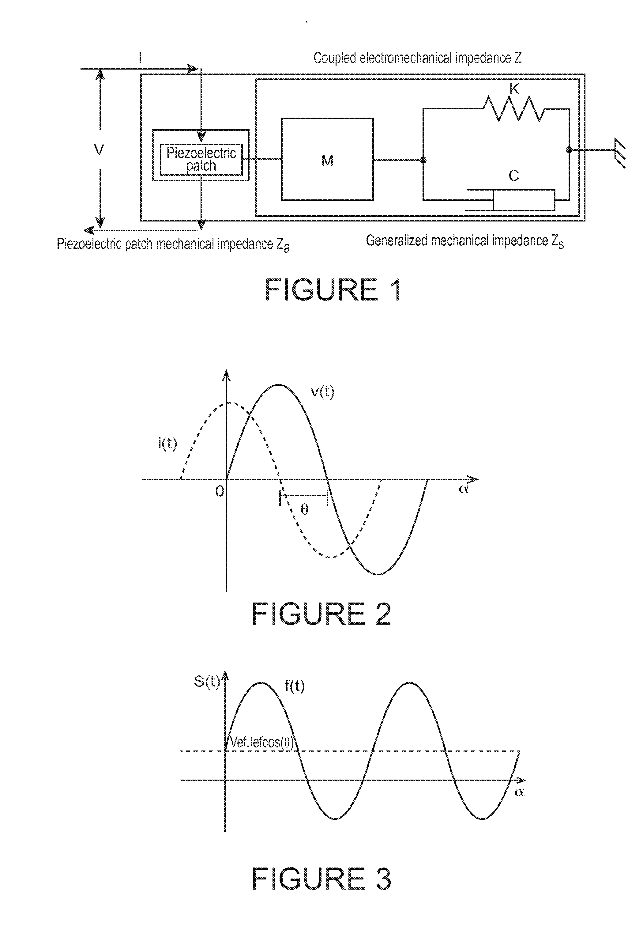
None. None. The technology herein relates to electronic sensing and analysis, and more particularly to methods, systems and techniques for acquiring the structural health state of an aircraft mechanical component based on ascertaining the mechanical impedance of the component. Aircraft parts can become stressed with use. While techniques are known for automatically analyzing changes in vibrational response, it would be helpful to be able to automatically sense and analyze changes in mechanical impedance using techniques that are less complicated, more efficient and less time consuming. These and other features and advantages will be better and more completely understood by referring to the following detailed description of example non-limiting illustrative embodiments in conjunction with the drawings of which: From Equation 1, Y(ω) is the electrical admittance (inverse of electrical impedance), Za and Zs are the PZT's and the structure's mechanical impedances, respectively, Ŷ112 is the complex Young's modulus of the PZT in the direction 1 under zero electric field, d31 is the piezoelectric coupling constant at zero stress, ∈33−T is the dielectric constant at zero stress, δ is the dielectric loss tangent of the piezoelectric patch, and a is a geometric constant of the PZT patch. This equation indicates that the electrical impedance of the PZT wafer bonded onto the structure is directly related to the mechanical impedance of the host structure. The EMI over a range of frequencies is analogous to a frequency response function (FRF) of the structure, which contains vital information regarding structural integrity. Damage causes direct changes in the structural stiffness and/or damping and alters the local dynamic characteristics of the system. As a result, the mechanical impedance is modified by structural damage. Assuming that the properties of the PZT patch remain constant, it turns out that Zs(ω) is the structure's impedance that uniquely determines the overall admittance of the electromechanical system. By monitoring the measured EMI and comparing it to a baseline measurement that corresponds to the pristine condition, one can qualitatively determine if incipient structural damage has occurred. The innovative method proposed herein from measuring each EMI FRF is based on the calculation of the resistive part of the electromechanical impedance of the active transducer, at each frequency point of interest, based on a simple and reduced set of equations. The instantaneous power consumed by the transducer, s(t), is obtained by multiplying Equation 2 by Equation 3. Equation 4 presents this result: The first term of Equation 4 is invariant over the time and includes sufficient information about the phase displacement between v(t) and i(t). The most commonly accepted electrical model of the complex impedance Z of the piezoelectric transducer is illustrated in Even though the average power is directly dependent on θ, there is no need to directly measure it. An example non-limiting specialized example circuit, illustrated in The process described is repeated for each frequency point in the previously specified range. The A more complete block diagram is presented in Environmental effects, such as the temperature illustrated in A complete example non-limiting flowchart for damage assessment is illustrated in After start, setup and calibration, the system loads/sets parameters (71) and activates the PZT transducers. The system calculates a frequency point and then starts signal generation. Two kinds of signal acquisition (current and power are acquired and respectively averaged. R is then calculated straightforwardly from I and P. This process can be repeated for multiple frequency points. Once the process has been performed for each of plural frequency points as desired, the system compensates for environmental effects. Then, if the data acquisition is for baseline purposes, the results are stored. If not baseline, then the results are compared with previously stored baseline information to assess damage based on the baseline. If damage is detected, an alert can be issued automatically to a pilot, crew or maintenance person. The technology herein may be embodied as a method, system hardware, embedded firmware and or software as a whole product or as a set of parts that work together in order to achieve the same or similar goal. The software part can be organized into two main sets. The first, called firmware, may be embedded in a microcontroller or any other processing system where preprocessing algorithms (averaging, analog and digital quantization and communication interfaces) are implemented to validate, correct and transfer the measurements to a computer system. The second set, called analysis software, can operate on a single or multiple computer (stand-alone) or other processing system either alone or connected in a network where remote operation and data visualization is possible. Post-processing algorithms (environmental effects compensation) and damage assessment can be combined to identify structural modifications (damages) at early stages. While the invention has been described in connection with what is presently considered to be the most practical and preferred embodiments, it is to be understood that the invention is not to be limited to the disclosed embodiments, but on the contrary, is intended to cover various modifications and equivalent arrangements included within the spirit and scope of the appended claims. A method to acquire the structural health state of an aircraft mechanical component performs measurements at each frequency point of interest by using a network of transducers and working each one simultaneously as actuator and sensor. Each transducer is individually excited by a sinusoidal, constant frequency and arbitrary amplitude, voltage waveform for each arbitrary frequency point used to interrogate the structure. A dedicated hardware executes an analogical (analog) quantization to measure electrical current and average electrical power consumed by each transducer. With these two variables, the electromechanical signature of the structure is obtained at different areas of the monitored structure. 1. A method for acquiring the health state of an object or a structural component using an EMI technique by performing measurements at each frequency point of the interest bandwidth by using one or more piezoelectric transducers operating as sensors/actuators at the same time, the method comprising:
a. providing sine wave excitation, at both constant frequency and amplitude, for each frequency point of interest; b. analog quantizing the RMS circulating current and the average consumed power of the transducer in order to directly measure the resistive part of the electromechanical impedance; c. compensating for environmental effects; and d. compensating for static and dynamic loading; e. wherein the method uses only one transducer to monitor the health state of a pre-determined area of an object or structure. 2. A method as set forth in 3. A method as set forth in 4. A method as set forth in 5. A method as set forth in 6. A method as set forth in 7. A method as set forth in 8. A method of 9. A system that can control a network of transducer in order to monitor larger structures, comprising:
an exciter structured to excite a mechanical object or structure with sine wave excitation for each frequency point of interest; a single transducer coupled to the mechanical object or structure used to monitor the health state of a pre-determined area of the object or structure; an analog quantizer that quantizes the RMS circulating current and the average consumed power of the transducer in order to directly measure the resistive part of the electromechanical impedance; and a processor coupled to the analog quantizer that compensates for environmental effects and static and dynamic loading. 10. The system of 11. The system of 12. The system that is set forth in 13. The system of CROSS-REFERENCE TO RELATED APPLICATIONS
STATEMENT REGARDING FEDERALLY SPONSORED RESEARCH OR DEVELOPMENT
FIELD
BACKGROUND
BRIEF DESCRIPTION OF THE DRAWINGS
DETAILED DESCRIPTION