BUTT JOINT WELDING APPARATUS AND METHOD THEREFOR
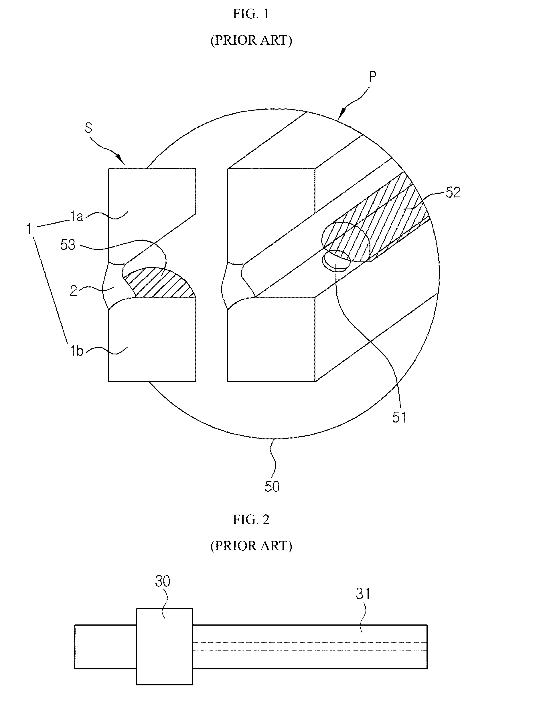
The present invention relates to a horizontal butt joint welding, and more particularly, to an apparatus and a method for deposited welding a horizontal butt joint which can weld a joint by deposited welding including welding of a root part. In general, a butt joint welding is to connect parent metals facing each other by welding, and is frequently used when iron plates are connected. In As shown in As described above, in case of applying flux cored arc welding using an automatic machine in relation with the horizontal butt joint, as shown in Moreover, in case of a low arc force, the upper parent metal forms an unwelded macro cross-section 53 (See The arc force means a power to push a molten pool, and generally, increases proportionally to the square of current and the double of voltage. In case that the arc force is weak, that is, in case that low current and low voltage are used, because arc radius 51 becomes smaller, molten metal 52 is formed small. Furthermore, a thin metal penetration is formed on the bottom surface of the parent metal because the force to push the small molten metal 52 also becomes smaller, and only the lower parent metal 1 Additionally, because a welding tip 31 of a general welding torch 30 is about 8 mm, in case that it carries out weaving at a small ad narrow space, the welding tip gets in contact with the bevel and it frequently causes short. In order to precisely weld the inside of the bevel, five to seven passes are needed. In addition, after welding the inside of the bevel, in case that welding of the surface part is carried out, because welding bead deflection frequently occurs due to influences of the low viscosity of the molten metal and gravity acting to the molten metal, the top bead has four or five passes to precisely weld if possible. In case of the conventional welding method, a parent metal with a thickness of 15 mm requires eight passes, and a parent metal with a thickness of 23 mm requires 10 to 15 passes as shown in In other words, in the conventional welding apparatus, the root part 2 is formed by carrying out root pass to the gaps 3 determined by the thickness of the parent metal and deposited welding of the inside of the bevel is carried out after the root part 2 is formed. However, even in case that deposited welding is carried out according to the thickness of the parent metal, like the cross sections of the welded parts #1 to #6 shown in the drawing, the multi-layered passes (10 to 15 passes) must be welded by the small deposit amount, and hence, there is a limitation in improving productivity through reduction of the number of the passes. Accordingly, the present invention has been made in an effort to solve the above-mentioned problems occurring in the prior arts, and it is an object of the present invention to provide automatic welding of a horizontal butt joint, and more particularly, an apparatus and a method for deposited welding a horizontal butt joint which can form a deposited welded part while forming a root part when deposited welding is carried out onto a bevel, thereby achieving deposited welding without any defect of the inside and surface of a welded cross section and reducing the number of welding passes. It is another object of the present invention to provide an apparatus and a method for deposited welding a horizontal butt joint which can prevent bead deflection in the direction of the surface of a groove and precedence of molten metal in the tangential direction during deposited weaving welding. To achieve the above objects, the present invention provides a horizontal butt joint deposited welding apparatus including: a traveling device part for conveying a welding tip vertically or slantingly to bevels of an upper parent metal and a lower parent metal; a welding torch which has a welding tip and is mounted in the traveling device part; a copper shoe device which is mounted in the traveling device part and is located in the welding direction by the welding tip in order to inject a gas to molten metal in the reverse direction to the welding direction; and a control unit for controlling welding conditions according to positions of the bevels in order to maintain a fixed deposition amount on the upper parent metal not to form a macro cross section on which a welded side is not formed, wherein the control unit enables the traveling device part to be conveyed along a particular weaving pattern including weaving traveling having a plurality of nodal points and diagonal traveling and controls welding current and voltage, wire supply speed, traveling speed, and stopping time at the nodal points in moving intervals between the nodal points to carry out deposited welding of the bevels. The welding current and voltage respectively have initial values according to the length of a gap (G) between the upper parent metal and the lower parent metal, and is varied in size at the two nodal points, which form a rear bead (B), to increase in proportion to the vertical width of the cross section of the bevel at the nodal point which forms a surface bead (F). In case that the stopping time for preheating at the two nodal points to form the rear bead (B) and producing an indefective bead is T1, the stopping time at each of the two nodal points for forming the rear bead (B) which carries out welding of the inside of the bevel and the stopping time of the nodal point for forming the surface bead (F) are 0.2*T1 within an error range of about ±10%. The stopping time at the nodal point for forming the surface bead (F) is 0.8*T1 within an error range of about ±10%. The wire supply speed is calculated to set an initial value at the nodal points for forming the rear bead (B) by the gap (G) and is calculated to increase more than the initial value at the nodal points located between the nodal points for forming the rear bead (B) and the surface bead (F) in proportion to the vertical width of the cross section of the bevel. The copper shoe device includes: a rear gas injection part; a front gas injection part; and a gas passage of a groove form which is formed on the opposite side of a side where the rear gas injection part and the front gas injection part are formed so as to get shallower toward the welding direction and is formed in such a way that a rear gas outlet of the rear gas injection part and a front gas outlet of the front gas injection part are located in the opposite direction to the welding direction. The gas injected by the copper shoe device has pressure stronger than a precedence force of molten metal. The traveling device part includes: an orthogonal weaving axis part for conveying the welding torch in the vertical direction of the bevel; and a traveling axis part for moving the welding torch along the bevel. The welding torch includes: a welding tip having the outer diameter of less than 8 mm; and an insulating coating layer formed on the outer circumferential surface of the welding tip. The traveling device part includes: a current detection sensor for detecting welding current; and a voltage detection sensor for detecting welding voltage. The control unit controls traveling speed of the traveling device part to maintain uniform deposition amount per unit volume using a current value and a voltage value of a voltage detection sensor. In another aspect of the present invention, there is a horizontal butt joint deposited welding method using a horizontal butt joint deposited welding apparatus, which includes: a traveling device part for conveying a welding tip vertically or slantingly to bevels of an upper parent metal and a lower parent metal; a welding torch which has a welding tip and is mounted in the traveling device part; a copper shoe device which is mounted in the traveling device part and is located in the welding direction by the welding tip in order to inject a gas to molten metal in the reverse direction to the welding direction; and a control unit which controls the traveling device part to be conveyed along a particular weaving pattern including weaving traveling having a plurality of nodal points and diagonal traveling, the horizontal butt joint deposited welding method including: a welding current and voltage calculating step for calculating welding current and welding voltage in a movement section between the nodal points by the control unit; a stopping time calculating step for calculating stopping time at each of the nodal points by the control unit; and a deposited welding step of carrying out deposited welding to the bevel without carrying out root pass welding by controlling a welding machine and the traveling device part according to the welding current and the welding voltage of each movement section between the nodal points calculated in the welding current and voltage calculating step and the stopping time at each nodal point calculated in the stopping time calculating step. The welding current and the welding voltage calculated in the welding current and voltage calculating step (S10) respectively have initial values according to the width of a gap (G) between the upper parent metal and the lower parent metal, and is varied in size at the two nodal points, which form a rear bead (B), to increase in proportion to the vertical width of the cross section of the bevel at the nodal point which forms a surface bead (F). In case that the stopping time calculating step (S20) for preheating at the two nodal points between the upper parent metal and the lower parent metal to form the rear bead (B) and producing an indefective bead is T1, the stopping time at each of the two nodal points for forming the rear bead (B) which carries out welding of the inside of the bevel and the stopping time of the nodal point for forming the surface bead (F) are 0.2*T1 within an error range of about ±10%, and the stopping time at the nodal point for forming the surface bead (F) is 0.8*T1 within an error range of about ±10%. The horizontal butt joint deposited welding method further includes a wire supply speed setting step (S30) of calculating wire supply speed to supply a wire of a proper amount for welding during movement between the nodal points. The wire supply speed calculated in the wire supply speed setting step (S30) is calculated to set an initial value at the nodal point for forming the rear bead (B) between the upper parent metal and the lower parent metal by the gap (G) between the upper parent metal and the lower parent metal, and is calculated to increase more than the initial value at the nodal points located between the nodal points for forming the rear bead (B) and the surface bead (F) in proportion to the vertical width of the cross section of the bevel. As described above, while carrying out weaving and diagonal traveling welding, the present invention controls weaving and diagonal traveling of the welding tip to have a plurality of the nodal points which stop weaving or diagonal traveling so that voltage intensity, current intensity and wire supply speed are varied in proportion to the width of the cross section of the bevel and the stopping time is varied in inverse proportion to the width of the cross section of the bevel to carry out deposited welding of one pass including welding of the root part. Therefore, the present invention can complete horizontal butt joint welding through deposited welding of one or two passes regardless of the thickness of the parent metal because about 50%, preferably, about 80%, of the cross section area inside the bevel is formed into a single pass welded part including the root part, thereby remarkably reducing the number of the passes and considerably enhancing speed of welding work. Moreover, the present invention carries out deposited welding on the inside and the surface of the welded cross section without defect by controlling current, voltage, wire supply speed and stopping time in proportion to the width of the cross section of the bevel during weaving welding and diagonal traveling welding, thereby remarkably enhancing welding quality. Furthermore, the apparatus and method for deposited welding the horizontal butt joint according to the present invention can prevent bead deflection in the direction of the surface of the groove and precedence of molten metal in the tangential direction during deposited weaving welding for the horizontal butt joint by injecting a gas to the molten metal in the reverse direction to the welding direction by the copper shoe device. Hereinafter, reference will be now made in detail to the preferred embodiments of the present invention with reference to the attached drawings. As shown in The configuration of the welding apparatus 100 of As shown in The copper shoe device 4 having the above configuration is located in the opposite direction to the welding torch 8 of the welding direction 13 as shown in After injecting the gas through the rear gas injection part 20 and the front gas injection part 21, the copper shoe device 4 sprays the gas 5 having pressure stronger than a preceding force of a molten metal 3 (see The gas pressure stronger than the preceding force of the molten metal 3 of the gas 5 sprayed by the copper shoe device 4 means pressure enough to prevent that the molten metal flows into the welding direction. The preceding force of the molten metal is arithmetically determined by an amount of the molten metal produced by welding current and welding voltage. Therefore, pressure of the gas sprayed by the copper shoe device 4 is determined by the preceding force arithmetically determined by the amount of the molten metal, and because the pressure value is varied according to welding situations, limitation of a concrete numerical value will be omitted. As shown in Referring to As shown in Moreover, as shown in The welding apparatus 100 carries out deposited welding having a particular weaving pattern 7 by the control unit 60 which controls voltage and current of an arc produced from the welding torch 8, movement and stopping time of the traveling axis part, and wire supply speed by each position of the bevel so as to directly carry out deposited welding at the first pass inside the bevel without carrying out root pass welding which forms the root part 2 to the gaps formed between the two parent metals 1 The control unit 60 which makes deposited welding possible during the first pass welding detects changes in welding output current and voltage, which are generated by a difference in wire resistances through changes in wire projection length 12 (see As shown in The welding current and the welding voltage calculated through the welding current and voltage calculating step (S10) are varied to set initial values according to the width of the gap G and to increase proportionally to the vertical width of the cross section of the bevel of the third nodal point P3 which forms the surface bead F at the first nodal point P1 and the fifth nodal point P5 forming the rear bead B. Additionally, in relation with the stopping time at each nodal point calculated during the stopping time calculating step (S20), in case that the stopping time for preheating at the first nodal point P1 and the fifth nodal point P5 for forming the rear bead B and producing an indefective bead is T1, stopping times T2 and T4 at the nodal points between the two nodal points P1 and P5 for forming the rear bead B which carries out welding of the inside of the bevel and the nodal point for forming the surface bead F are 0.2*T1 within an error range of about ±10%, and the stopping time at the nodal point for forming the surface bead F is 0.8*T1 within an error range of about ±10%. Moreover, the horizontal butt joint deposited welding method according to the present invention further includes a wire supply speed setting step (S30) of calculating wire supply speed for supplying a wire of a proper amount to carry out welding during movement between the nodal points. The initial value at the nodal points for setting the rear bead B is set by the gap G, and the wire supply speed calculated in the wire supply speed calculating step (S30) is calculated to increase more than the initial value in proportion to the vertical width of the cross section of the bevel at the nodal points located between the nodal points for forming the rear bead B and the nodal point for forming the surface bead F. The deposited welding step (S100) directly carries out deposited welding of the first pass inside the bevel of the welding progress side without carrying root pass welding to remove a step difference between the upper parent metal and the lower parent metal on the opposite side of the welding progress side. In other words, in the deposited welding step (S100), welding is controlled to have different stopping times, voltages, currents and wire supply speeds at the nodal points, and movement speed between the nodal points is controlled to have a value varied according to the width of the gap G. Satisfaction of welding conditions at each nodal point or welded part is determined by the welding current and welding voltage detected by the welding current detection sensor 61 Furthermore, the stopping time at each nodal point and movement between the nodal points are carried out by the traveling motor driving part 65 and the weaving motor driving part 66 of Additionally, the welding current, the welding voltage and the wire supply speed are controlled by the control unit 60 which controls the welding machine 68. As shown in The particular weaving pattern 7 carries out weaving traveling in a section of the first nodal point P1 which is the first root part→the second nodal point P2 which is the first middle part→the third nodal point P3 which is the surface part so that only the orthogonal weaving axis part 41 moves in the Y-axis direction and carries out diagonal traveling in a section of the third nodal point P3 which is the surface part→the fourth nodal point P4 which is the second middle part→the fifth nodal point P5 which is the second root part so that the orthogonal weaving axis part 41 and the traveling axis part 40 operate at the same time to weave in the diagonal direction. Moreover, the stopping time T to stop at each nodal point to produce a fixed deposition amount and conveying speed S between the nodal points have a predetermined speed value proportional to the width of the gap G determined by the thickness of the parent metal, and the welding current and the welding voltage have the minimum values at the first nodal point P1 and the fifth nodal point P5 which form the rear bead B and the maximum values at the third nodal point P3 which forms the surface bead F. Furthermore, the nodal points located between the first nodal point P1 and the fifth nodal point P5 for forming the rear bead B and the third nodal point P3 for forming the surface bead F have sizes proportional to the width of the cross section of the bevel. In order to carry out the horizontal butt joint deposited welding by the particular weaving pattern 7, as shown in Referring to In Additionally, the welding current IR and the welding voltage VR of the first nodal point P1 and the fifth nodal point P5 are controlled to have 263 A and 31.2V within an error range of about ±10%, the welding current IM and the welding voltage VM of the second nodal point P2 and the fourth nodal point P4 are controlled to have 359 A and 33.2V within an error range of about ±10%, and the welding current IF and the welding voltage VF at the third nodal point P3 is controlled to have 421 A and 35.7V within an error range of about ±10%. In addition, the moving speed between the nodal points P1 to P5 is maintained uniformly at 2 cm/sec, and is increased to have a predetermined speed value in proportion to the width of the gap G or the bevel. Moreover, the wire supply speed WR between the first nodal point P1 and the second nodal point P2 is 1028 cm/min within an error range of about ±10%, the wire supply speed WM between the second nodal point P2 and the third nodal point P3 is 1727 cm/min within an error range of about ±10%, the wire supply speed WF between the third nodal point P3 and the fourth nodal point P4 is 2139 cm/min within an error range of about ±10%, and the wire supply speed WM between the fourth nodal point P4 and the fifth nodal point P5 is 1727 cm/min within an error range of about ±10%. Furthermore, carriage traveling speed is average about 10.6 cm/min from the first nodal point P1 to fifth nodal point P5. As shown in In the deposited welding step (S100), because the stopping time is the longest at the first nodal point P1 and the fifth nodal point P5 for forming the rear bead B (See In the above step, as shown in When horizontal butt joint welding is carried out by applying the welding method of Because the performance of the particular weaving pattern 7 minimizes the diameter of the welding tip 32 of the welding torch 8 and forms the insulating coating layer 33 on the outer circumferential surface, it makes the welding tip weave freely and prevents stop of arc generation by insulation even though the upper parent metal 1 Next, while the above welding step is carried out, the copper shoe device 4 injects the gas 5 to the molten metal 56 by control of the control unit 60. The copper shoe device 4 injects the gas of the predetermined pressure in the opposite direction to the welding direction in consideration of the amount of the molten metal produced by the control unit 60 using information of welding current and welding voltage and traveling control information of the orthogonal weaving axis part 41 and the traveling axis part 40. The gas injected during the gas injection process prevents that the molten metal formed by the large arc force flows toward the welding torch 8 by the gas pressure stronger than the precedence force of the molten metal. The large molten metal 56 formed during the welding process is pushed up to the bevel of the upper parent metal 1 After the molten metal 56 is formed by the arc force, the movement direction, speed and stopping time of the orthogonal weaving axis part 41 and the traveling axis part 40 are controlled according to the stopping time and the moving speed between the nodal points which are calculated by the stopping time calculating step (S20) of As described above, in case that horizontal butt joint welding is carried out to the two parent metals through the horizontal butt joint deposited welding method which carries out the welding condition control of the particular weaving pattern 7, the welding current, the welding voltage, the stopping time, the wire supply speed and the traveling speed are calculated by welding of the first pass to weld 50% to 100% of the welded part. Therefore, when the initial deposited welding which is the first pass welding inside the bevel is carried out without performing root pass welding, as shown in A butt joint welding apparatus and method are provided. The apparatus comprises a traveling device part to convey a welding tip vertically or slantingly to the bevel of upper and lower parent metal. A welding torch with a welding tip is mounted in the traveling device part. A copper shoe device is mounted in the traveling device part and positioned in the direction of welding by the welding tip for ejecting a gas to the molten metal in the direction reverse to the welding direction. A control unit controls the welding condition according to the positions of the bevels of the butt joint welding. The control unit enables the traverse device part to be conveyed along a particular weaving pattern, and controls the welding current and voltage, the wire supply speed, the traverse speed, and the stopping time at the nodal points in the moving interval between adjacent nodal points. 1. A horizontal butt joint welding apparatus comprising:
a traveling device part to convey a welding tip vertically or slantingly to bevels of an upper parent metal and a lower parent metal; a welding torch comprising a welding tip and mounted in the traveling device part; a copper shoe device mounted in the traveling device part and located in a welding direction by the welding tip to inject a gas to a molten metal in a reverse direction to the welding direction; a control unit to control welding conditions according to positions of the bevels to maintain a fixed deposition amount on the upper parent metal not to form a macro cross section on which a welded side is not formed; and wherein the control unit enables the traveling device part to be conveyed along a particular weaving pattern including weaving traveling having a plurality of nodal points and diagonal traveling and controls welding current and voltage, wire supply speed, traveling speed, and stopping time at the nodal points in moving intervals between the nodal points to carry out deposited welding of the bevels. 2. The horizontal butt joint welding apparatus according to 3. The horizontal butt joint deposited welding apparatus according to 4. The horizontal butt joint deposited welding apparatus according to 5. The horizontal butt joint deposited welding apparatus according to 6. A horizontal butt joint deposited welding method using a horizontal butt joint deposited welding apparatus, comprising: a traveling device part to convey a welding tip vertically or slantingly to bevels of an upper parent metal and a lower parent metal; a welding torch comprising a welding tip and mounted in the traveling device part; a copper shoe device mounted in the traveling device part and located in a welding direction by the welding tip to inject a gas to molten metal in a reverse direction to the welding direction; and a control unit to control the traveling device part to be conveyed along a particular weaving pattern including weaving traveling having a plurality of nodal points and diagonal traveling, the horizontal butt joint deposited welding method comprising:
a welding current and voltage calculating step of calculating welding current and welding voltage in a movement section between the nodal points by the control unit; a stopping time calculating step of calculating stopping time at each of the nodal points by the control unit; and a deposited welding step of carrying out deposited welding to the bevel without carrying out root pass welding by controlling a welding machine and the traveling device part according to the welding current and the welding voltage of each movement section between the nodal points calculated in the welding current and voltage calculating step and the stopping time at each nodal point calculated in the stopping time calculating step. 7. The horizontal butt joint deposited welding method according to 8. The horizontal butt joint deposited welding method according to 9. The horizontal butt joint deposited welding method according to TECHNICAL FIELD
BACKGROUND ART
DISCLOSURE
Technical Problem
Technical Solution
ADVANTAGEOUS EFFECTS
DESCRIPTION OF DRAWINGS
MODE FOR INVENTION