Multiple Effect Concentration Swap De-Scaling System
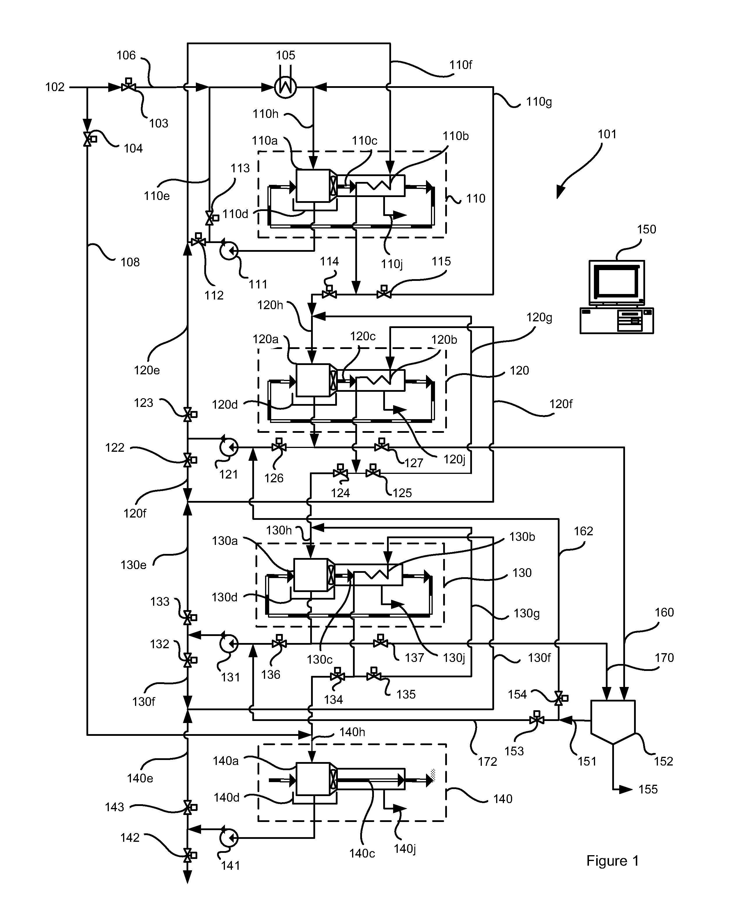
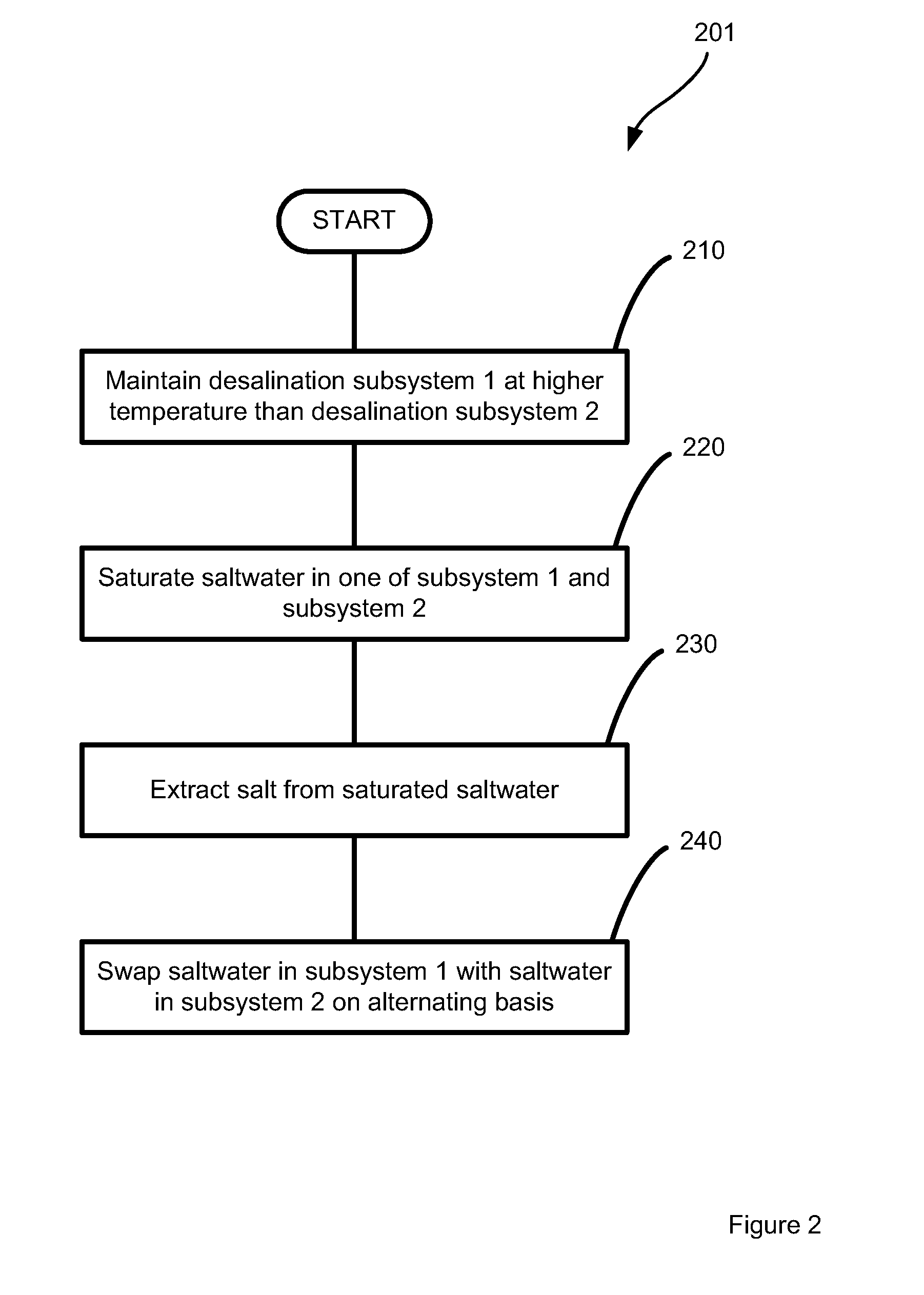
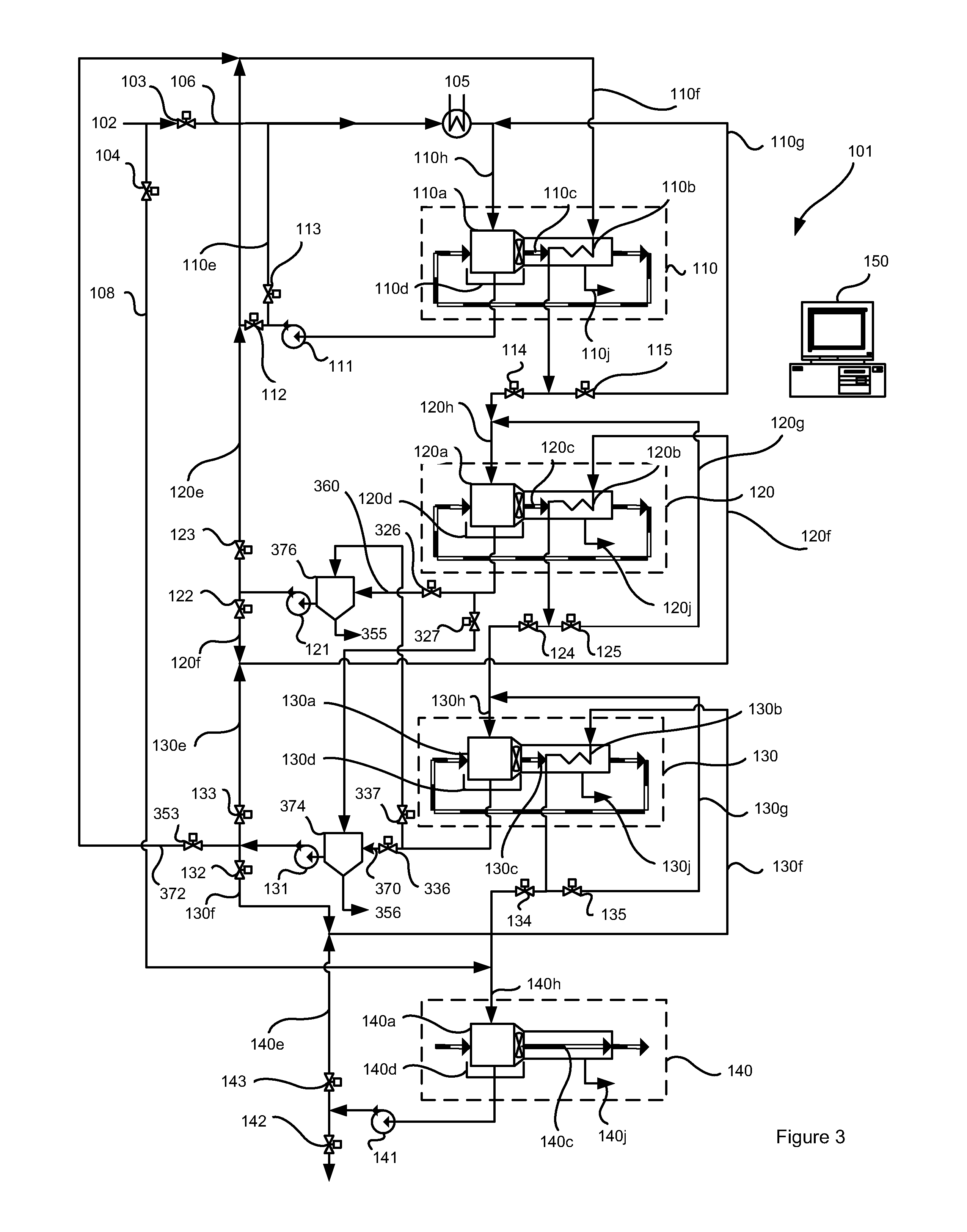
The present disclosure provides a method to improve the reliability of multiple effect evaporation or flash desalination processes. More specifically, the method periodically swaps the concentration of the saltwater processed in each effect to enable de-scaling during operation. Treatment of waste saltwater to reduce volume is becoming increasingly important, particularly for mining, oil and gas, and inland desalination systems. Mines can produce tailings water, which is typically ponded. Oil and gas operations can produce saltwater within the hydrocarbon reserve or during processing. Desalination is increasingly being used in both industries as regulations require treatment of impaired water. Desalination is also used in coastal regions to produce freshwater from seawater, with the more saline brine reject returned to the ocean. Inland brackish water can be desalted; however, there is often no convenient way to dispose of the brine reject. Common brine reject management options include discharge to a sewer or the environment, ponding, deep well injection, or treatment to produce solid salt in concentrators and crystallizers. The first two methods are becoming more challenging to use due to tightening environmental regulations and associated costs. This is moving the emphasis to so-called Zero Liquid Discharge (ZLD) processes. In such processes, concentrators and crystallizers are used to distil water and produce solids, which can then be landfilled or put to secondary use. Due to the need to operate at high concentrations that exceed the osmotic pressure limits of reverse osmosis systems, such ZLD processes involve an evaporation-condensation cycle. In such evaporation-condensation cycles, the water in the saline saltwater waste is evaporated to a nearly pure vapor and condensed to recover nearly pure liquid water. Despite their popularity, ZLD processes are expensive, costing roughly five times as much as employing traditional deep wells. ZLD processes also experience considerable reliability challenges due to the inherent saturation point operation. The capital costs of ZLD processes are high due to the extensive use of alloyed steels and titanium required at the operating temperatures and pressures. Energy costs are high due to the use of large volume compressors, which on average consume 20 to 60 kWh of electrical-mechanical power per cubic meter treated. Considerable effort has been focused on multiple effect thermal desalination processes. These comprise a cascade of evaporation-condensation processes, each subsequent process in the cascade operating at a temperature below that of the previous process in the cascade. A given evaporation-condensation process in the cascade obtains its required latent heat of evaporation from the heat of condensation resulting from a preceding higher temperature evaporation-condensation process. Humidification dehumidification (HDH) is one form of multiple effect thermal desalination, described in Canadian Patent Application 2,816,746, the entirety of which is hereby incorporated by reference herein. In brief, an air stream is humidified by warm saltwater, which drips through a humidification zone to promote heat and mass transfer from the warm saltwater to the air stream, with said air stream having a wet bulb temperature lower than the warm saltwater temperature. The humidified air stream is then cooled by a radiator surface that is colder than the wet bulb temperature of the humidified air. As air is cooled, the air's ability to hold vapor decreases and moisture condenses on the cooler tubes while transferring its heat of condensation to the cooler saltwater inside the radiator tubes, which is then directed to the humidifier of the subsequently lower temperature effect. Operation of the system described in Canadian Patent Application 2,816,746 may be at or above saturation. However, saturated operation increases the propensity of solids and scale to build up on internal surfaces, reducing heat transfer effectiveness and clogging flow paths resulting in performance degradation and reliability challenges. In fact, the most common reoccurring maintenance required in any humidification driven saltwater concentrating system is de-scaling the system components. Therefore, there is also a need to devise a system that efficiently and periodically removes scaling in multiple effect desalination processes. Canadian Patent Application 2,821,453, the entirety of which is hereby incorporated by reference herein, describes one such method to periodically clean internal surfaces through a series of freshwater or chemically enhanced wash cycles based on predetermined operating criteria. Additional methods, systems, and techniques for de-scaling desalination systems continue to be developed. According to a first aspect, there is provided a multistage desalination system. The system comprises a higher stage desalination subsystem comprising a first evaporation stage for evaporating a first saltwater at a first temperature and a first condensation stage, fluidly coupled to the first evaporation stage, for condensing product water from vapor that evaporates from the saltwater in the first evaporation stage; a lower stage desalination subsystem comprising a second evaporation stage for evaporating a second saltwater at a second temperature and a second condensation stage, fluidly coupled to the second evaporation stage, for condensing product water from vapor that evaporates from the saltwater in the second evaporation stage, wherein the second temperature is lower than the first temperature; a first pump and a second pump fluidly coupled to the higher and lower stage desalination subsystems, respectively, for pumping the saltwaters through the desalination subsystems; at least one transfer conduit fluidly coupling the higher and lower stage desalination systems; and valving fluidly coupled at least to the at least one transfer conduit. The valving is configurable to operate the multistage desalination system in a normal mode in which the first and second saltwaters are evaporated and condensed in the higher and lower stage desalination subsystems, respectively, and in a swapped mode in which the first and second saltwaters are swapped and subsequently evaporated and condensed in the lower and higher stage desalination subsystems, respectively. The system may further comprise a heat exchanger thermally coupling the first condensation stage to the second evaporation stage for transferring heat from the first condensation stage to the second evaporation stage. Each of the higher and lower stage desalination systems may comprise a multiple-effect distillation system or a multi-stage flash distillation system. The first evaporation stage may comprise a first humidifier, the first condensation stage may comprise a first dehumidifier, the second evaporation stage may comprise a second humidifier, and the second condensation stage may comprise a second dehumidifier. A first carrier gas for conveying the vapor evaporated in the first humidifier may flow through a first closed loop carrier gas circuit comprising the first humidifier and the first dehumidifier and a second carrier gas for conveying the vapor evaporated in the second humidifier may flow through a second closed loop carrier gas circuit comprising the second humidifier and the second dehumidifier. The at least one transfer conduit may comprise a down-transfer conduit permitting fluid transfer from the higher stage desalination subsystem to the lower stage desalination subsystem, and operation in the normal mode may comprise pumping the first saltwater from the higher stage desalination subsystem that is not evaporated in the first evaporation stage to the second evaporation stage for further evaporation. The at least one transfer conduit may comprise an up-transfer conduit permitting fluid transfer from the lower stage desalination subsystem to the higher stage desalination subsystem, and transitioning from the normal to the swapped modes may comprise pumping the second saltwater to the higher stage desalination subsystem via the up-transfer conduit and the first saltwater to the lower stage desalination subsystem via the down-transfer conduit. The down-transfer conduit may pass through the first dehumidifier and be fluidly coupled to the second humidifier, and the product water may condense on to a portion of the down-transfer conduit within the first dehumidifier. The up-transfer conduit may fluidly couple the first humidifier to a location on the down-transfer conduit between the first dehumidifier and the second humidifier. When in the normal mode the first saltwater may flow through a first closed loop saltwater circuit comprising the first humidifier and the second saltwater may flow through a second closed loop saltwater circuit, non-overlapping with the first closed loop saltwater circuit, comprising the down-transfer conduit and the second humidifier. The system may further comprise a salt extraction system for extracting solid salts or an aqueous solution; brine transfer conduits fluidly coupling the salt extraction system to the first and second closed loop saltwater circuits; and brine discharge valving, located along the brine transfer conduits, operable to selectably route the first saltwater from the first closed loop saltwater circuit or the second saltwater from the second closed loop saltwater circuit to the salt extraction system. The system may further comprise salinity sensors located along the first and second closed loop saltwater circuits; and a controller communicatively coupled to the salinity sensors and the brine discharge valving. The controller may be configured to perform a method comprising (i) determining, using the salinity sensors, the salt concentration of the first and second saltwaters; and (ii) when the salt concentration of the first or second saltwater equals or exceeds a swapping threshold: (1) transferring the second saltwater to the salt extraction system; (2) transferring to the second closed loop saltwater circuit the waste brine that the salt extraction system outputs; and (3) waiting at least a swapping period prior to again transferring the second saltwater to the salt extraction system and transferring the waste brine to the second closed loop saltwater circuit. The swapping threshold may be the salt concentration of the first or second saltwater when at saturation. The system may further comprise salinity sensors located along the first and second closed loop saltwater circuits; and a controller communicatively coupled to the salinity sensors and the valving. The controller may be configured to perform a method comprising determining, using the first and second salinity sensors, the salt concentration of the first and second saltwaters; when the salt concentration of the first or second saltwater meets or exceeds a swapping threshold, transitioning between the normal and swapped modes; and waiting at least a swapping period prior to again transitioning between the normal and swapped modes. The swapping threshold may be the salt concentration of the first or second saltwater when at saturation. The first humidifier may comprise a first drainage basin and the second humidifier may comprise a second drainage basin, and the method may further comprise, prior to transitioning between the normal and swapped modes, draining at least some of the first and second saltwaters into the first and second drainage basins, respectively, by slowing the pump. The brine discharge valving may also be operable to return waste brine that the salt extraction system outputs to the first or second closed loop saltwater circuits and the method may further comprise, after transitioning between the normal and swapped modes transferring the saltwater in the first closed loop saltwater circuit to the salt extraction system; and transferring to the first closed loop saltwater circuit the waste brine that the salt extraction system outputs. The system may further comprise a pressure or flow sensor located along the first or second closed loop saltwater circuit; and a controller communicatively coupled to the pressure or flow sensor and the valving. The controller may be configured to perform a method comprising determining, using the pressure or flow salinity sensor, the pressure or flow rate within the first or second closed loop saltwater circuit; when the pressure or flow rate equals or exceeds a swapping threshold, transitioning between the normal and swapped modes; and waiting at least a swapping period prior to again transitioning between the normal and swapped modes. A controller may be communicatively coupled to the valving and configured to transition between the normal and swapped modes in response to elapsed time of desalination. The controller may wait different times to transition from the normal mode to the swapped mode and to transition from the swapped mode to the normal mode. When in the normal mode the first saltwater may flow through a first closed loop saltwater circuit comprising the first humidifier and a first saltwater reservoir and the second saltwater may flow through a second closed loop saltwater circuit, non-overlapping with the first closed loop saltwater circuit, comprising the second humidifier and a second saltwater reservoir, and swapping from the normal mode to the swapped mode may comprise configuring the valving so the first humidifier is fluidly coupled to the second saltwater reservoir and so the second humidifier is fluidly coupled to the first saltwater reservoir. The at least one transfer conduit may comprise a down-transfer conduit permitting fluid transfer from the higher stage desalination subsystem to the lower stage desalination subsystem, and operation in the normal mode may comprise pumping the first saltwater from the higher stage desalination subsystem that is not evaporated in the first evaporation stage to the second evaporation stage for further evaporation. The down-transfer conduit may pass through the first dehumidifier and be fluidly coupled to the second humidifier, and the product water may condense on to a portion of the down-transfer conduit within the first dehumidifier. The system may further comprise a first and a second salt extraction system for extracting solid salts or an aqueous solution, and the first and the second salt extractions systems may comprise the first and the second saltwater reservoirs, respectively. The system may further comprise a salinity sensor located along the first and second closed loop saltwater circuit; and a controller communicatively coupled to the salinity sensors and the valving. The controller may be configured to perform a method comprising determining, using the salinity sensor, the salt concentration of the first and second saltwater; when the salt concentration of the first or the second saltwater equals or exceeds a swapping threshold, transitioning between the normal and the swapped modes; and waiting at least a swapping period prior to again transitioning between the normal and swapped modes. The swapping threshold may be the salt concentration of the second saltwater when at saturation. The system may further comprise a pressure or flow sensor located along the first or second closed loop saltwater circuit; and a controller communicatively coupled to the pressure or flow sensor and the valving. The controller may be configured to perform a method comprising determining, using the pressure or flow salinity sensor, the pressure or flow rate within the first or second closed loop saltwater circuit; when the pressure or flow rate equals or exceeds a swapping threshold, transitioning between the normal and swapped modes; and waiting at least a swapping period prior to again transitioning between the normal and swapped modes. The system may further comprise a controller communicatively coupled to the valving, and the controller may be configured to transition between the normal and swapped modes in response to elapsed time of desalination. The controller may wait different times to transition from the normal mode to the swapped mode and to transition from the swapped mode to the normal mode. According to another aspect, there is provided a method for reducing scaling in a multistage desalination system comprising higher and lower stage desalination subsystems. The method comprises desalinating a first saltwater in a higher stage desalination subsystem, wherein desalinating the first saltwater comprises evaporating the first saltwater at a first temperature and condensing product water from vapor that evaporates from the first saltwater; desalinating a second saltwater in a lower stage desalination subsystem, wherein desalinating the second saltwater comprises evaporating the second saltwater at a second temperature lower than the first temperature and condensing product water from vapor that evaporates from the second saltwater; and swapping the first and second saltwaters. The method may further comprise prior to desalinating the second saltwater, transferring heat released by condensation of the product water in the higher stage desalination subsystem to the second saltwater. Each of the higher and lower stage desalination systems may comprise a multiple-effect distillation system or a multi-stage flash distillation system. The higher stage desalination subsystem may comprise a first humidifier for evaporating the first saltwater and a first dehumidifier for condensing the product water from the vapor that evaporates from the first saltwater; the lower stage desalination subsystem may comprise a second humidifier for evaporating the second saltwater and a second dehumidifier for condensing the product water from the vapor that evaporates from the second saltwater; desalinating the first saltwater may comprise conveying from the first humidifier to the first dehumidifier, via a first carrier gas, the vapor evaporated from the first saltwater, wherein the first carrier gas flows through a first closed loop carrier gas circuit comprising the first humidifier and the first dehumidifier; and desalinating the second saltwater may comprise conveying from the second humidifier to the second dehumidifier, via a second carrier gas, the vapor evaporated from the second saltwater, wherein the second carrier gas flows through a second closed loop carrier gas circuit comprising the second humidifier and the second dehumidifier. The method may further comprise, after evaporating the first saltwater in the higher stage desalination subsystem, transferring the first saltwater to the second evaporation stage and then further evaporating the first saltwater in the second evaporation stage. The method may further comprise determining the salt concentration of the second saltwater; and when the salt concentration of the second saltwater meets or exceeds a swapping threshold, extracting solid salts or an aqueous solution from the second saltwater. The second saltwater may flow through a second closed loop saltwater circuit comprising the second humidifier during desalination, and extracting the solid salts or the aqueous solution from the second saltwater may comprise transferring the second saltwater to a salt extraction system and using the salt extraction system to extract the solid salts or the aqueous solution; and transferring to the second closed loop saltwater circuit waste brine that the salt extraction system outputs. The swapping threshold may be the salt concentration of the first or second saltwater when at saturation. The method may further comprise determining the salt concentration of the first and second saltwaters, wherein the first and second saltwaters are swapped when the salt concentration of the first or second saltwaters meets or exceeds a swapping threshold; and waiting at least a swapping period prior to again swapping the first and second saltwaters. The swapping threshold may be the salt concentration of the second saltwater being at saturation. During desalination, the first saltwater may circulate through a first closed loop saltwater circuit comprising the first humidifier and the second saltwater may circulate through a second closed loop saltwater circuit comprising the second humidifier, and swapping the first and second saltwaters may comprise slowing circulation of the first and second saltwaters through the first and second closed loop saltwater circuits, respectively; purging one of the first and second saltwaters from one of the first and second humidifiers, respectively; and transferring the other of the first and second saltwaters to the humidifier that was purged. Purging may comprise one or both of draining the one of the first and second saltwaters into a drainage basin and injecting compressed air into the one of the first and second humidifiers. The method may further comprise after swapping the first and second saltwaters, extracting solid salts or an aqueous solution from the saltwater in the first closed loop saltwater circuit. Extracting the solid salts or the aqueous solution from the saltwater in the first closed loop saltwater circuit may comprise transferring the saltwater in the first closed loop saltwater circuit to the salt extraction system and using the salt extraction system to extract the solid salts or the aqueous solution; and transferring to the first closed loop saltwater circuit the waste brine that the salt extraction system outputs. The method may further comprise determining the salt concentration of the first and second saltwaters, wherein the first and second saltwaters are swapped when the salt concentration of the first or second saltwaters meets or exceeds a swapping threshold; and waiting at least a swapping period prior to again swapping the first and second saltwaters. The swapping threshold may be the salt concentration of the first or second saltwater when at saturation. The method may further comprise determining the pressure or flow rate within the first or second closed loop saltwater circuits, wherein the first and second saltwaters are swapped when the pressure or flow rate exceeds a swapping threshold; and waiting at least a swapping period prior to again swapping the first and second saltwaters. The method may further comprise swapping the first and second saltwaters in response to elapsed time of desalination. During desalination, the first saltwater may circulate through a first closed loop saltwater circuit comprising the first humidifier and a first saltwater reservoir and the second saltwater may circulate through a second closed loop saltwater circuit comprising the second humidifier and a second saltwater reservoir. Swapping the first and second saltwaters may comprise fluidly decoupling the first humidifier and the first saltwater reservoir from each other and the second humidifier and the second saltwater reservoir from each other; fluidly coupling the first humidifier and the second saltwater reservoir together and the second humidifier and the first saltwater reservoir together; and desalinating the saltwater in the first saltwater reservoir using the lower stage desalination system and desalinating the saltwater in the second saltwater reservoir using the higher stage desalination system. The first saltwater reservoir may comprise part of a first salt extraction system and the second saltwater reservoir may comprise part of a second salt extraction system, and the method may further comprise extracting solid salts or an aqueous solution from the first and second saltwaters using the saltwater extraction systems. The method may further comprise determining the salt concentrations of the first and second saltwaters, wherein the first and second saltwaters are swapped when the salt concentration of the first or second saltwaters meets or exceeds a swapping threshold; and waiting at least a swapping period prior to again swapping the first and second saltwaters. The swapping threshold may be the salt concentration of the second saltwater when at saturation. The method may further comprise determining the pressure or flow rate within the first or second closed loop saltwater circuits, wherein the first and second saltwaters are swapped when the pressure or flow rate exceeds a swapping threshold; and waiting at least a swapping period prior to again swapping the first and second saltwaters. The method may further comprise swapping the first and second saltwaters in response to elapsed time of desalination. According to another aspect, there is provided a non-transitory computer readable medium having encoded thereon statements and instructions to cause a controller to perform any of the foregoing aspects of the method or suitable combinations thereof. This summary does not necessarily describe the entire scope of all aspects. Other aspects, features and advantages will be apparent to those of ordinary skill in the art upon review of the following description of specific embodiments. In the accompanying drawings, which illustrate one or more example embodiments: Embodiments described herein are directed to a multi-effect thermal desalination system arranged for changing the order in which physical thermal desalination subsystems are applied in a multi-effect thermal desalination system. The term “multi-effect thermal desalination system” is used herein to describe a thermal desalination system comprising more than one thermal desalination subsystem and therefore more than one associated desalination process stage. An example embodiment of the system and method disclosed herein is based on a multi-effect humidification dehumidification (HDH) thermal desalination system. At least some of the embodiments described herein are directed to reducing the frequency of or need for washing the desalination system, and to mitigating the negative consequences of adding freshwater to a solution being concentrated. First thermal desalination subsystem 110 comprises a first humidification zone 110 The heated first saltwater from conduit 110 The primary saltwater feed for thermal desalination subsystem 110 is the raw saltwater input to the overall system 101 via valve 103 and conduit 106. The fourth thermal desalination subsystem 140 similarly takes as its primary saltwater feed the raw saltwater input to the overall system 101 via valve 104 and conduit 108. For this reason first and fourth thermal desalination subsystems 110 and 140 operate at lower salt concentration levels than second and third desalination subsystems 120 and 130. The second saltwater in conduit 120 Third saltwater to be desalinated in third thermal desalination subsystem 130 flows in the third closed loop saltwater circuit from 130 In the depicted example embodiment the fourth thermal desalination subsystem 140 is also fed directly via valve 104 from the saltwater input to the overall system 101. Fourth saltwater in the fourth closed loop saltwater circuit of fourth thermal desalination subsystem 140 evaporates in fourth humidification zone 140 In the above arrangement, typical temperatures may be as follows, assuming a heat source 105 temperature of 82 to 85° C. The temperature of first saltwater entering first humidification zone 110 The flow pattern described thus far represents the default closed circuit operating configuration of the system 101, in which the highest temperatures are attained in thermal desalination subsystem 110, and the lowest in thermal desalination subsystem 140, while the highest salt concentrations are attained in thermal desalination subsystem 130, and the lowest salt concentrations are attained in thermal desalination subsystems 110 and 140, while a medium level of salt concentration is maintained in thermal desalination subsystem 120. The closed circuit saltwater circuit through the humidification zone 120 Within this arrangement, the first saltwater in the first closed loop saltwater circuit through humidification zone 110 In the above normal mode, typical salt concentrations may be 100,000 mg/L in the first and fourth closed loop saltwater circuits through conduits 110 The valving arrangements for transferring saltwater downward in the thermal cascade of thermal desalination subsystems 110,120,130,140, as employed in the description immediately above. This process is referred to in the present description as “blow-down”, as the saltwater is moved from a higher temperature thermal desalination subsystem to a lower temperature desalination subsystem. Referring to the highest temperature desalination subsystem, being 110. To effect the blow-down, valve 113 may be shut and valve 112 opened. With valve 123 shut, the saltwater from humidification zone 110 In equivalent fashion, saltwater may be transferred from humidifier 120 In equivalent fashion, saltwater may be transferred from humidifier 130 There is no blow-down process from desalination subsystem 140 as it is the last one in the temperature cascade of system 101. The valving arrangement for transferring saltwater upward in the thermal cascade of thermal desalination subsystems 110,120,130,140 is now considered. This process is referred to in the present specification as “blow-up”, as the saltwater is moved from a lower temperature thermal desalination subsystem to a higher temperature desalination subsystem. Consider first the lowest temperature desalination subsystem, being the fourth desalination subsystem 140. To effect the blow-up process, valves 142, 132, and 134 may be shut and valves 143 and 135 opened. Saltwater from humidifier 140 In equivalent fashion, saltwater may be transferred from humidifier 130 In equivalent fashion, saltwater may be transferred from humidifier 120 There is no blow-up process from the first desalination subsystem 110, as it is the highest temperature desalinator in the temperature cascade of system 101. As may be seen from the above detailed explanation, conduits 110 On the basis of the valving arrangements described above, any fluid transfer process, whether “blow-up”/“up-transfer” or “blow-down”/“down-transfer”, between any two mutually adjacent desalination subsystems in system 101 may be conducted independently from whatever processes may be in operation in the remaining desalination subsystems in system 101. In the present disclosure, a reference to a “fluid” may be a reference to one or both of a liquid and a gas. In As the system 101 operates in its default or normal mode described above, it may build-up scale on internal surfaces; in particular build-up may occur in the desalination subsystem operating with the highest salt concentration saltwater. In normal mode this subsystem is thermal desalination subsystem 130, and in particular build-up occurs on its humidifier 130 The periodic lowering of the salt concentration in the desalination subsystem with the highest default salt concentration is accomplished in what is termed in this disclosure “swapped mode” to prevent irreversible solid and scale build up on internal surfaces. In the embodiment of In respect of the embodiment of Controller 150 in Parameters such as drain time, pump speed, pump ramp up time, and pump ramp down time can be adjusted to avoid excessive mixing of the second saltwater and third saltwater. Required values of these parameters are primarily dependent on the volumes of basins 120 In another embodiment a method [201] is provided for reducing scaling in multistage desalination system (101) comprised of at least a first (120) and a second (130) desalination subsystem, the method comprising maintaining [210] a first closed loop saltwater circuit of the first desalination subsystem at a higher temperature than a second closed loop saltwater circuit of the second desalination subsystem; saturating [220] saltwater in one of the first and second closed loop saltwater circuits; extracting [230] salt from the saturated saltwater; and swapping [240] on an alternating basis the saturated saltwater in the one of the first and second closed loop saltwater circuits with the saltwater in the other of the first and second closed loop saltwater circuits. The extracting may be by inserting a salt extraction system in the closed loop saltwater circuit containing the saturated water. In a first configuration, desalination subsystems 110,120,130,140 are arranged in order of decreasing saltwater circuit temperature, wherein first saltwater in conduit 110 Third saltwater in conduit 130 Valve configuration for the transferring of saltwater down the thermal desalination subsystems 110,120,130,140, as described in first configuration above, is referred to as “blow-down”. The blow-down involves saltwater transfer from higher temperature thermal desalination subsystems to lower temperature desalination subsystem in a process configuration similar to The valve configuration for the transferring of saltwater up the thermal desalination subsystems 110,120,130,140 is now considered. This process is referred to as “blow-up” and involves saltwater transfer from the lowest temperature thermal desalination subsystems to higher temperature desalination subsystems in a process configuration similar to As described above in respect of the embodiment of When the embodiment of The third saltwater in the third closed loop saltwater circuit of third thermal desalination subsystem 130 is swapped with the second saltwater in the second closed loop saltwater circuit of second thermal desalination subsystem 120 as follows. Initiation of swap mode stops pump 131, discontinues closed loop flow to allow drainage into basin 130 Similar to For the embodiments of both In the foregoing embodiments, swapping is done between two adjacent subsystems 110,120,130,140 of the system 101. However, in alternative embodiments (not depicted), swapping may be done between any of the subsystems 110,120,130,140, and not necessarily just those that are adjacent. The above detailed description is based on a humidification dehumidification (HDH) thermal desalination system 101. However, the method and swapped arrangement may also be applied to a steam-based desalination system such as a multi-stage flash distillation system or a multiple-effect distillation system, with the principle involved being the in-line swapping of a high salt concentration desalination subsystem with a similar lower concentration desalination subsystem, while simultaneously switching saltwater reservoirs (which may comprise each comprise part of a salt extraction subsystem) between the two desalination subsystems. Operation is between normal and swapped modes in a periodic manner to prevent solid and scale build-up. In general, the system and method are not limited to a particular kind of desalination system. It is contemplated that any part of any aspect or embodiment discussed in this specification can be implemented or combined with any part of any other aspect or embodiment discussed in this specification. While particular embodiments have been described in the foregoing, it is to be understood that other embodiments are possible and are intended to be included herein. It will be clear to any person skilled in the art that modification of and adjustments to the foregoing embodiments, not shown, are possible. A multistage thermal desalination system, together with its associated method of use, allows de-scaling of subsystems exposed to saturated saltwater by alternating the saturation stage of the process between two neighboring physical desalination stages. The desalination system is provided with at least one transfer conduit, at least one pump, and valving to permit saltwaters being desalinated by higher and lower stage desalination subsystems to be swapped. By replacing the saturated saltwater in a higher salt concentration desalination subsystem with lower salt concentration saltwater, the scaling in higher salt concentration desalination subsystem is reduced while the saturation load is placed on another of the desalination subsystems. 1. A multistage desalination system comprising:
(a) a higher stage desalination subsystem comprising a first evaporation stage for evaporating a first saltwater at a first temperature and a first condensation stage, fluidly coupled to the first evaporation stage, for condensing product water from vapor that evaporates from the saltwater in the first evaporation stage; (b) a lower stage desalination subsystem comprising a second evaporation stage for evaporating a second saltwater at a second temperature and a second condensation stage, fluidly coupled to the second evaporation stage, for condensing product water from vapor that evaporates from the saltwater in the second evaporation stage, wherein the second temperature is lower than the first temperature; (c) a first pump and a second pump fluidly coupled to the higher and lower stage desalination subsystems, respectively, for pumping the saltwaters through the desalination subsystems; (d) at least one transfer conduit fluidly coupling the higher and lower stage desalination systems; and (e) valving fluidly coupled at least to the at least one transfer conduit, the valving configurable to operate the multistage desalination system in a normal mode in which the first and second saltwaters are evaporated and condensed in the higher and lower stage desalination subsystems, respectively, and in a swapped mode in which the first and second saltwaters are swapped and subsequently evaporated and condensed in the lower and higher stage desalination subsystems, respectively. 2. The system of 3. The system of 4. The system of 5. The system of 6. The system of 7. The system of 8. The system of 9. The system of 10. The system of (a) a salt extraction system for extracting solid salts or an aqueous solution; (b) brine transfer conduits fluidly coupling the salt extraction system to the first and second closed loop saltwater circuits; and (c) brine discharge valving, located along the brine transfer conduits, operable to selectably route the first saltwater from the first closed loop saltwater circuit or the second saltwater from the second closed loop saltwater circuit to the salt extraction system. 11. The system of (a) salinity sensors located along the first and second closed loop saltwater circuits; and (b) a controller communicatively coupled to the salinity sensors and the brine discharge valving, the controller configured to perform a method comprising:
(i) determining, using the salinity sensors, the salt concentration of the first and second saltwaters; and (ii) when the salt concentration of the first or second saltwater equals or exceeds a swapping threshold:
(1) transferring the second saltwater to the salt extraction system; (2) transferring to the second closed loop saltwater circuit the waste brine that the salt extraction system outputs; and (3) waiting at least a swapping period prior to again transferring the second saltwater to the salt extraction system and transferring the waste brine to the second closed loop saltwater circuit. 12. The system of 13. The system of (a) salinity sensors located along the first and second closed loop saltwater circuits; and (b) a controller communicatively coupled to the salinity sensors and the valving, the controller configured to perform a method comprising:
(i) determining, using the first and second salinity sensors, the salt concentration of the first and second saltwaters; (ii) when the salt concentration of the first or second saltwater meets or exceeds a swapping threshold, transitioning between the normal and swapped modes; and (iii) waiting at least a swapping period prior to again transitioning between the normal and swapped modes. 14. The system of 15. The system of 16. The system of (a) transferring the saltwater in the first closed loop saltwater circuit to the salt extraction system; and (b) transferring to the first closed loop saltwater circuit the waste brine that the salt extraction system outputs. 17. The system of (a) a pressure or flow sensor located along the first or second closed loop saltwater circuit; and (b) a controller communicatively coupled to the pressure or flow sensor and the valving, the controller configured to perform a method comprising:
(i) determining, using the pressure or flow salinity sensor, the pressure or flow rate within the first or second closed loop saltwater circuit; (ii) when the pressure or flow rate equals or exceeds a swapping threshold, transitioning between the normal and swapped modes; and (iii) waiting at least a swapping period prior to again transitioning between the normal and swapped modes. 18. The system of 19. The system of 20. The system of 21. The system of 22. The system of 23. The system of 24. The system of (a) a salinity sensor located along the first and second closed loop saltwater circuit; and (b) a controller communicatively coupled to the salinity sensors and the valving, the controller configured to perform a method comprising:
(i) determining, using the salinity sensor, the salt concentration of the first and second saltwater; (ii) when the salt concentration of the first or the second saltwater equals or exceeds a swapping threshold, transitioning between the normal and the swapped modes; and (iii) waiting at least a swapping period prior to again transitioning between the normal and swapped modes. 25. The system of 26. The system of (a) a pressure or flow sensor located along the first or second closed loop saltwater circuit; and (b) a controller communicatively coupled to the pressure or flow sensor and the valving, the controller configured to perform a method comprising:
(i) determining, using the pressure or flow salinity sensor, the pressure or flow rate within the first or second closed loop saltwater circuit; (ii) when the pressure or flow rate equals or exceeds a swapping threshold, transitioning between the normal and swapped modes; and (iii) waiting at least a swapping period prior to again transitioning between the normal and swapped modes. 27. The system of 28. The system of 29. A method for reducing scaling in a multistage desalination system comprising higher and lower stage desalination subsystems, the method comprising:
(a) desalinating a first saltwater in a higher stage desalination subsystem, wherein desalinating the first saltwater comprises evaporating the first saltwater at a first temperature and condensing product water from vapor that evaporates from the first saltwater; (b) desalinating a second saltwater in a lower stage desalination subsystem, wherein desalinating the second saltwater comprises evaporating the second saltwater at a second temperature lower than the first temperature and condensing product water from vapor that evaporates from the second saltwater; and (c) swapping the first and second saltwaters. 30. The method of 31. The method of 32. The method of (a) the higher stage desalination subsystem comprises a first humidifier for evaporating the first saltwater and a first dehumidifier for condensing the product water from the vapor that evaporates from the first saltwater; (b) the lower stage desalination subsystem comprises a second humidifier for evaporating the second saltwater and a second dehumidifier for condensing the product water from the vapor that evaporates from the second saltwater; (c) desalinating the first saltwater comprises conveying from the first humidifier to the first dehumidifier, via a first carrier gas, the vapor evaporated from the first saltwater, wherein the first carrier gas flows through a first closed loop carrier gas circuit comprising the first humidifier and the first dehumidifier; and (d) desalinating the second saltwater comprises conveying from the second humidifier to the second dehumidifier, via a second carrier gas, the vapor evaporated from the second saltwater, wherein the second carrier gas flows through a second closed loop carrier gas circuit comprising the second humidifier and the second dehumidifier. 33. The method of 34. The method of (a) determining the salt concentration of the second saltwater; and (b) when the salt concentration of the second saltwater meets or exceeds a swapping threshold, extracting solid salts or an aqueous solution from the second saltwater. 35. The method of (a) transferring the second saltwater to a salt extraction system and using the salt extraction system to extract the solid salts or the aqueous solution; and (b) transferring to the second closed loop saltwater circuit waste brine that the salt extraction system outputs. 36. The method of 37. The method of (a) determining the salt concentration of the first and second saltwaters, wherein the first and second saltwaters are swapped when the salt concentration of the first or second saltwaters meets or exceeds a swapping threshold; and (b) waiting at least a swapping period prior to again swapping the first and second saltwaters. 38. The method of 39. The method of (a) slowing circulation of the first and second saltwaters through the first and second closed loop saltwater circuits, respectively; (b) purging one of the first and second saltwaters from one of the first and second humidifiers, respectively; and (c) transferring the other of the first and second saltwaters to the humidifier that was purged. 40. The method of 41. The method of 42. The method of 43. The method of (a) transferring the saltwater in the first closed loop saltwater circuit to the salt extraction system and using the salt extraction system to extract the solid salts or the aqueous solution; and (b) transferring to the first closed loop saltwater circuit the waste brine that the salt extraction system outputs. 44. The method of (a) determining the salt concentration of the first and second saltwaters, wherein the first and second saltwaters are swapped when the salt concentration of the first or second saltwaters meets or exceeds a swapping threshold; and (b) waiting at least a swapping period prior to again swapping the first and second saltwaters. 45. The method of 46. The method of (a) determining the pressure or flow rate within the first or second closed loop saltwater circuits, wherein the first and second saltwaters are swapped when the pressure or flow rate exceeds a swapping threshold; and (b) waiting at least a swapping period prior to again swapping the first and second saltwaters. 47. The method of 48. The method of (a) fluidly decoupling the first humidifier and the first saltwater reservoir from each other and the second humidifier and the second saltwater reservoir from each other; (b) fluidly coupling the first humidifier and the second saltwater reservoir together and the second humidifier and the first saltwater reservoir together; and (c) desalinating the saltwater in the first saltwater reservoir using the lower stage desalination system and desalinating the saltwater in the second saltwater reservoir using the higher stage desalination system. 49. The method of 50. The method of (a) determining the salt concentrations of the first and second saltwaters, wherein the first and second saltwaters are swapped when the salt concentration of the first or second saltwaters meets or exceeds a swapping threshold; and (b) waiting at least a swapping period prior to again swapping the first and second saltwaters. 51. The method of 52. The method of (a) determining the pressure or flow rate within the first or second closed loop saltwater circuits, wherein the first and second saltwaters are swapped when the pressure or flow rate exceeds a swapping threshold; and (b) waiting at least a swapping period prior to again swapping the first and second saltwaters. 53. The method of 54. A non-transitory computer readable medium having encoded thereon statements and instructions to cause a controller to perform a method for reducing scaling in a multistage desalination system as claimed in TECHNICAL FIELD
BACKGROUND
SUMMARY
BRIEF DESCRIPTION OF THE DRAWINGS
DETAILED DESCRIPTION