UNINTERRUPTIBLE POWER-SUPPLY SYSTEM
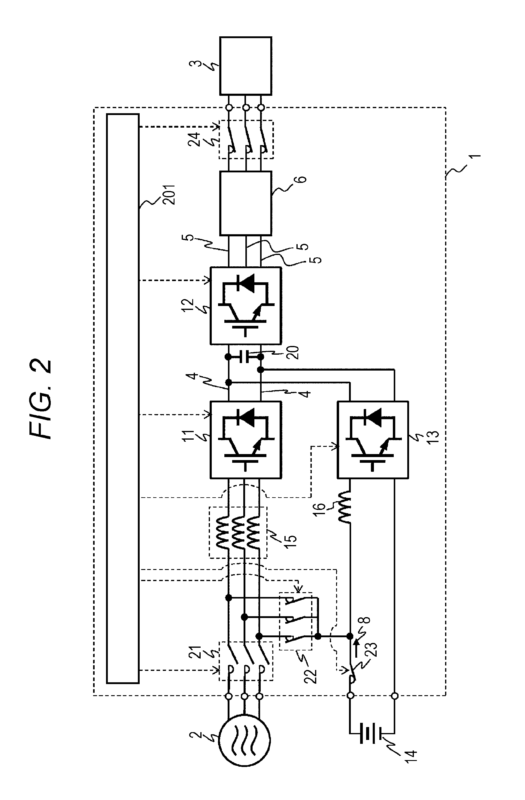
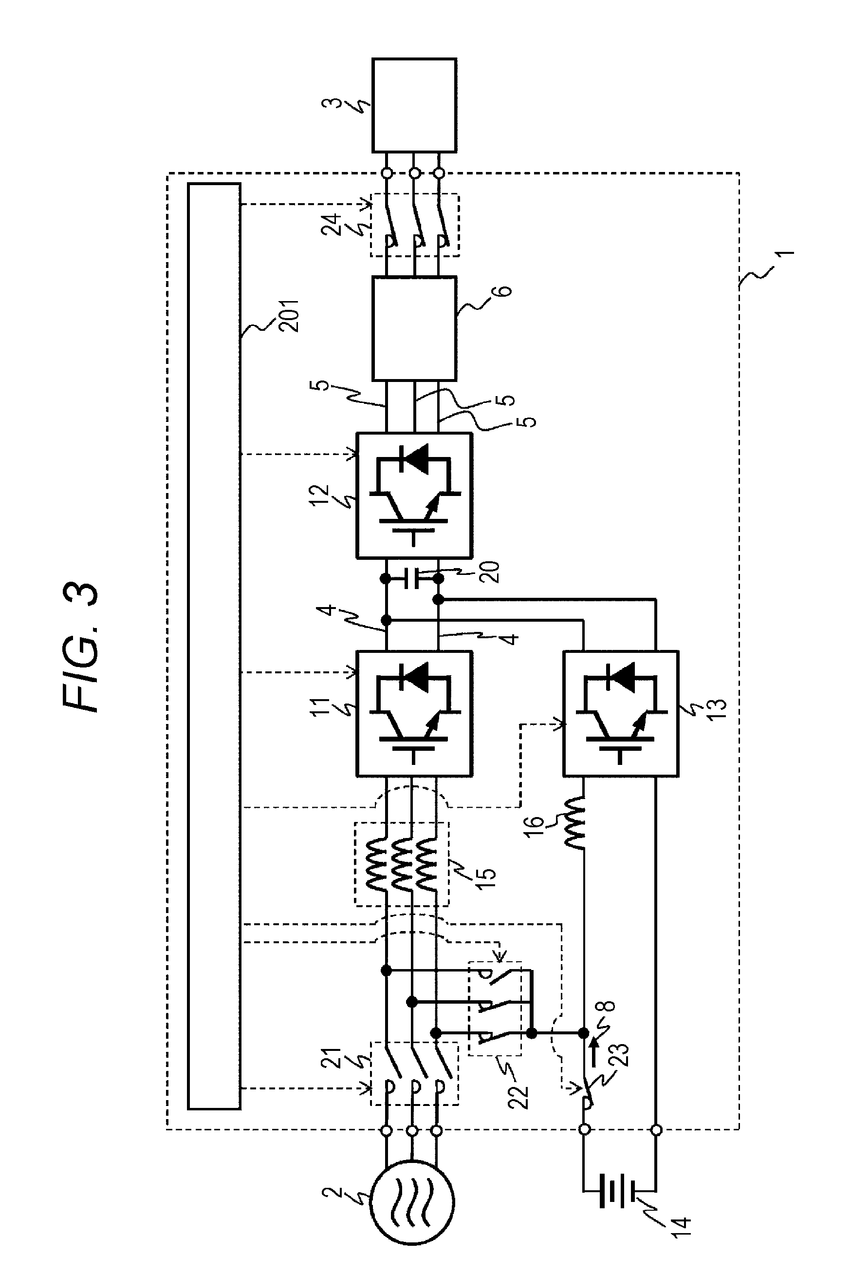
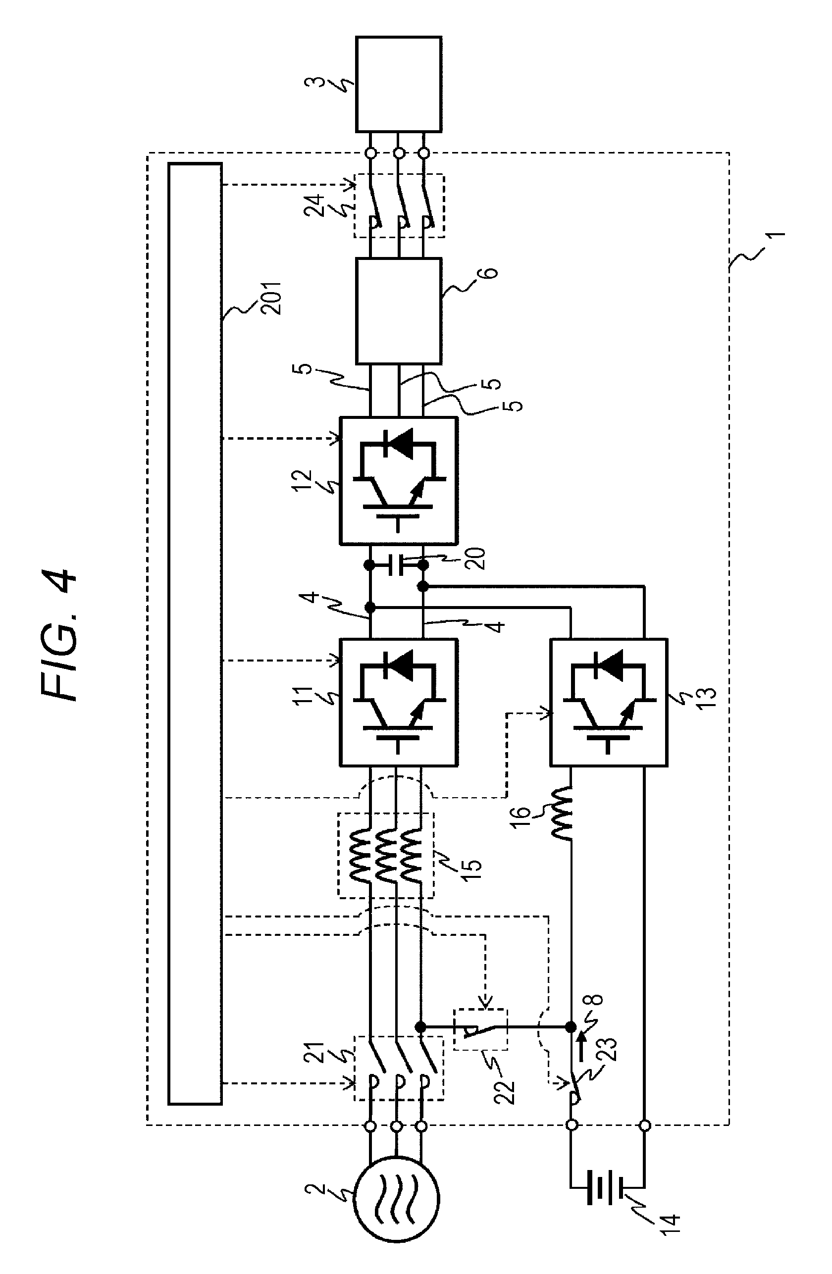
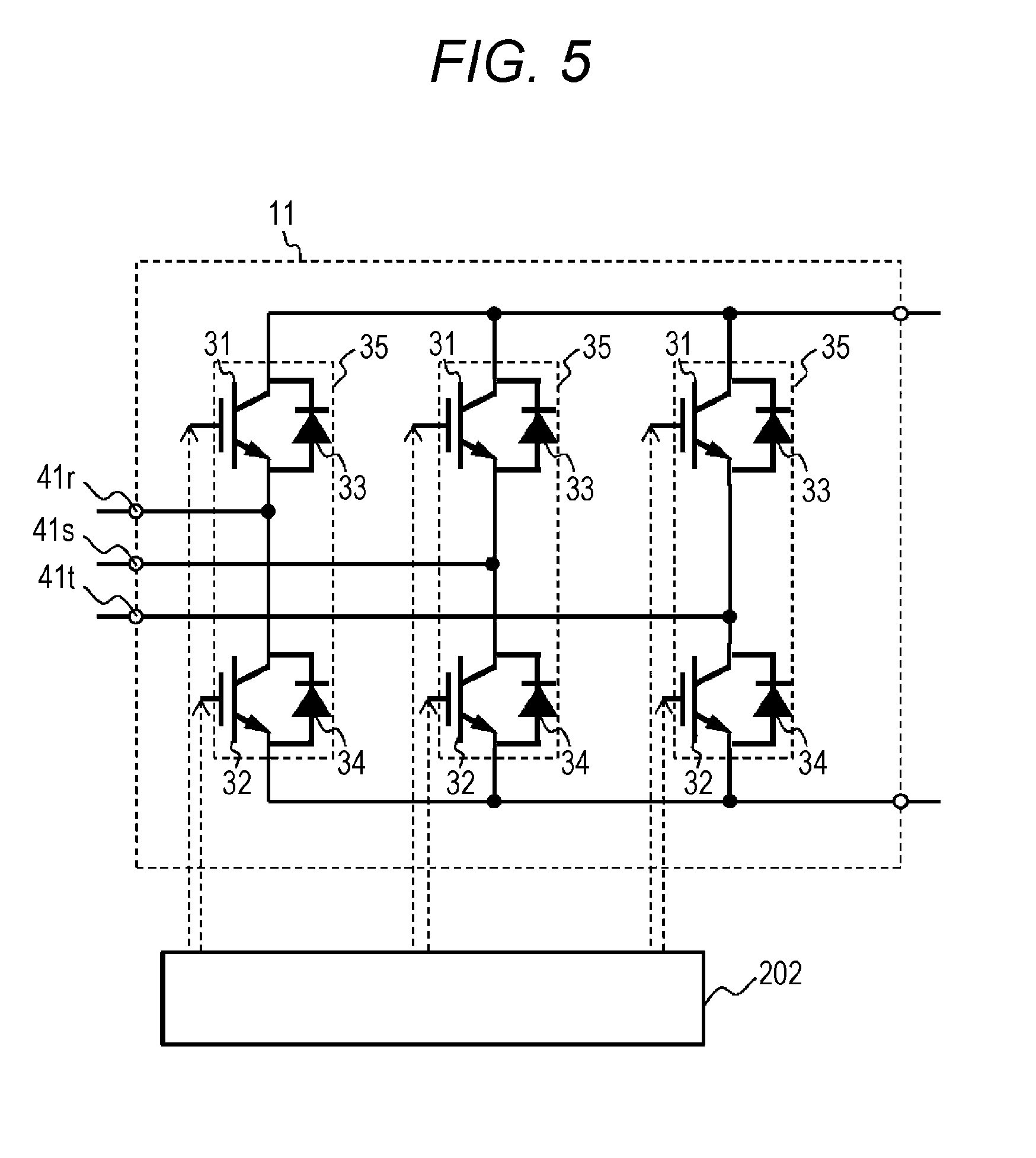
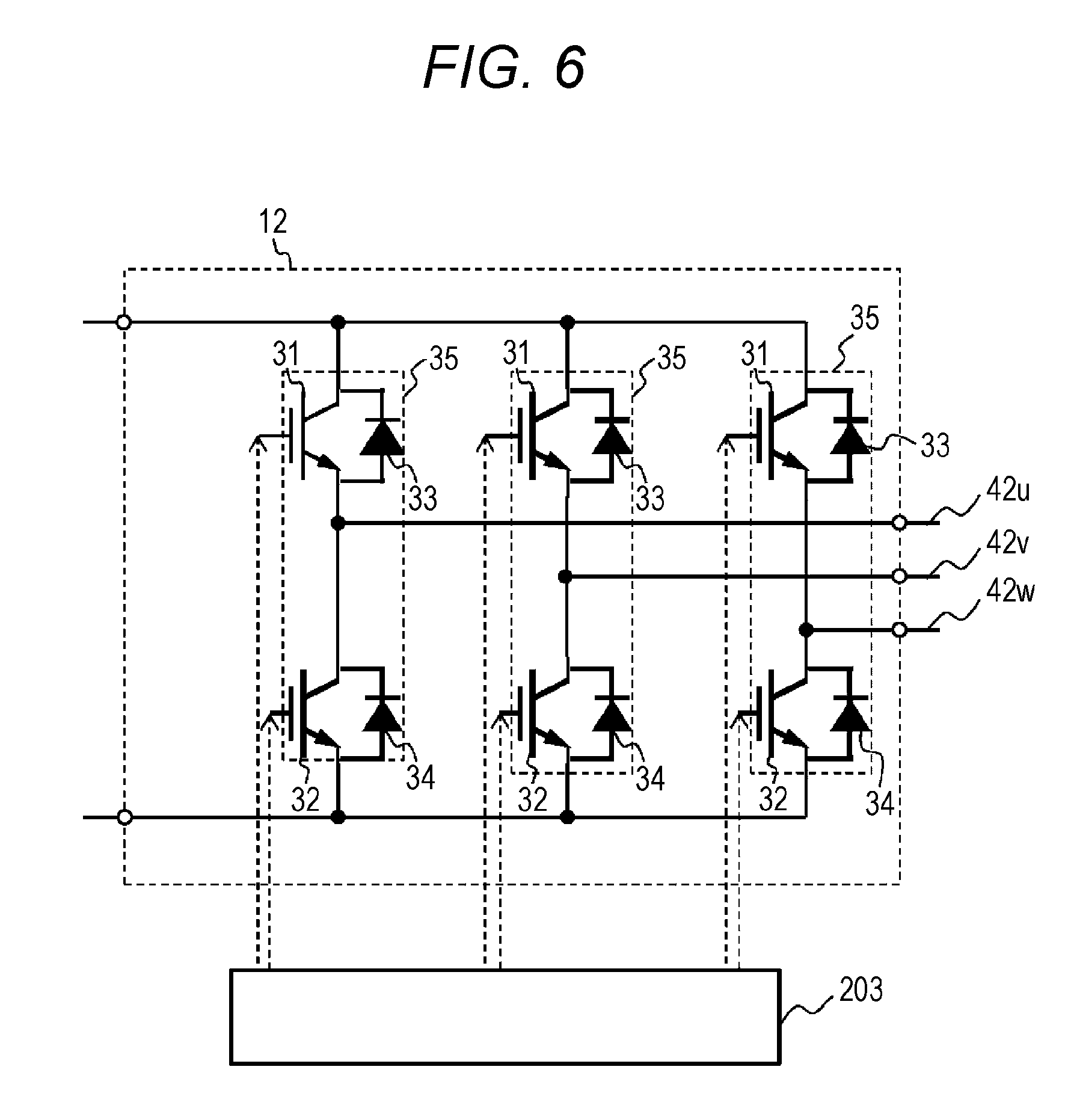
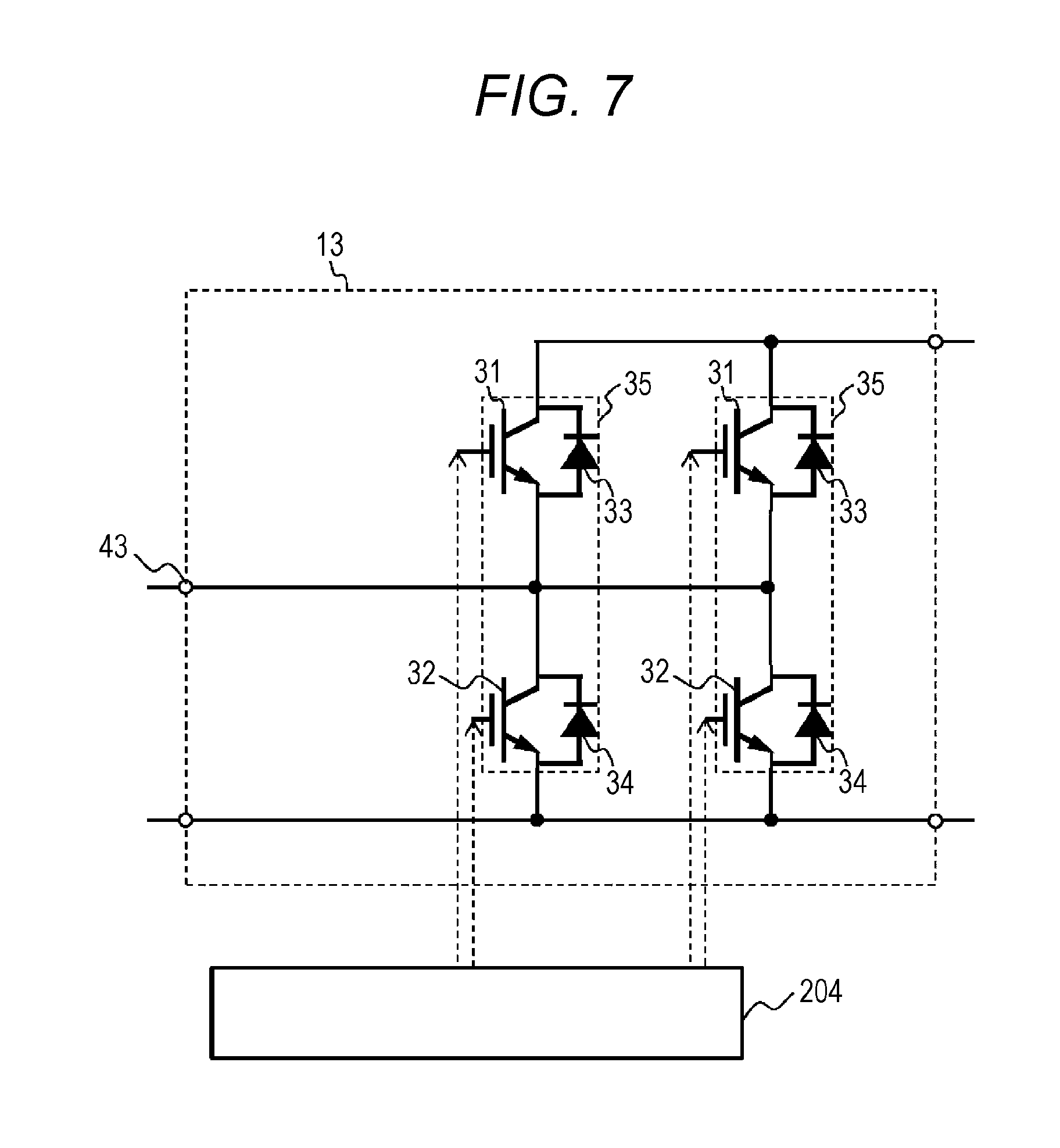
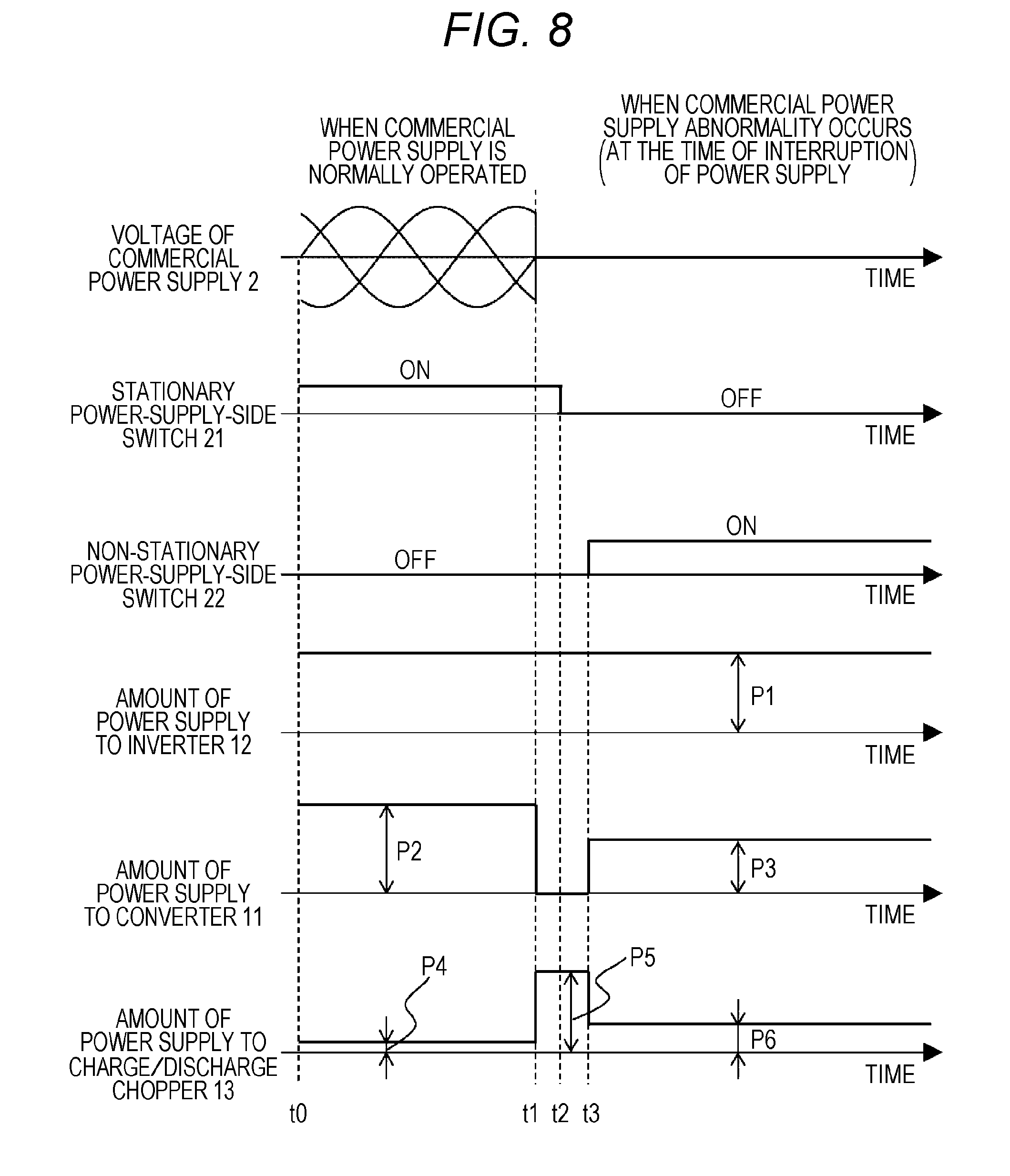
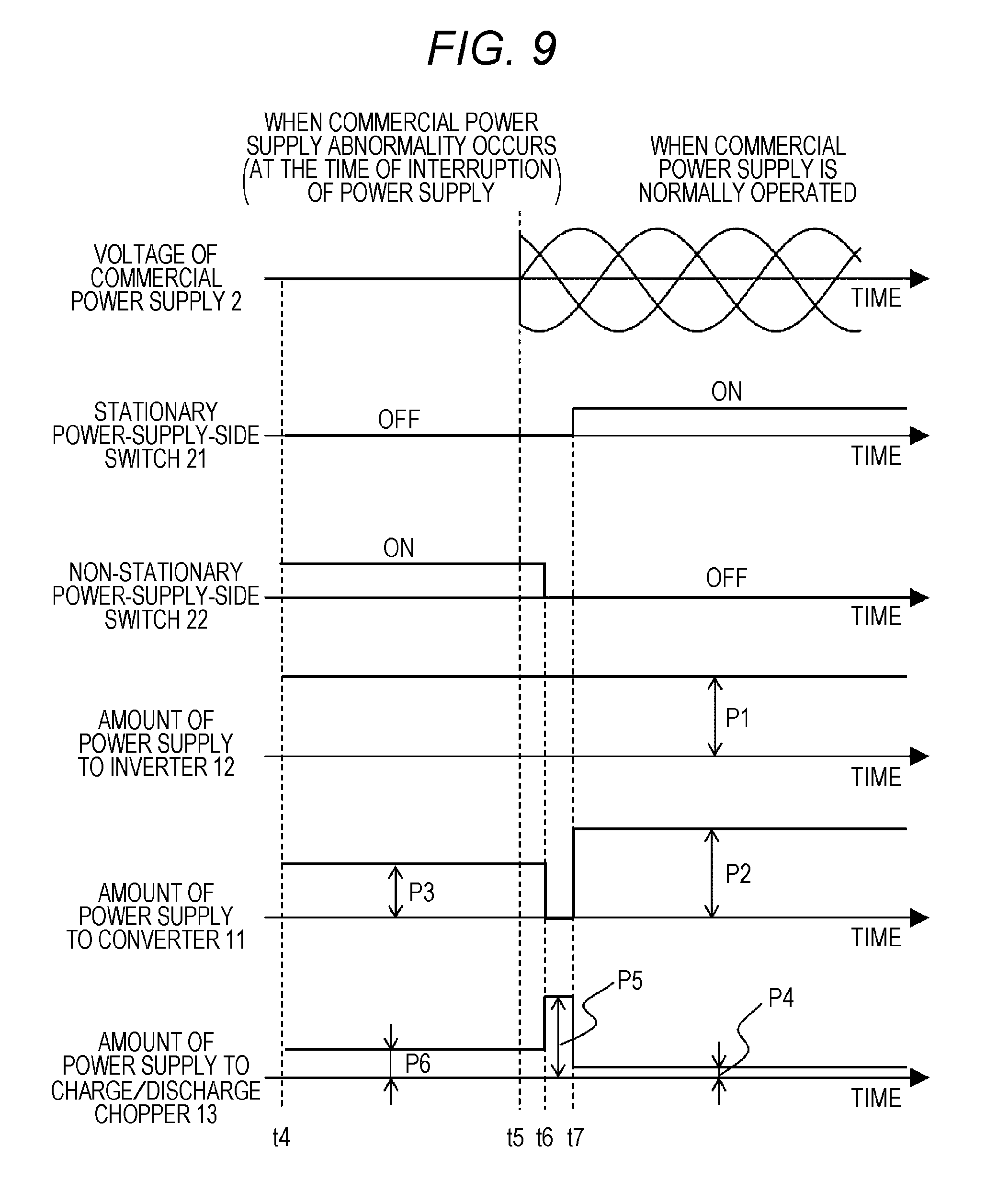
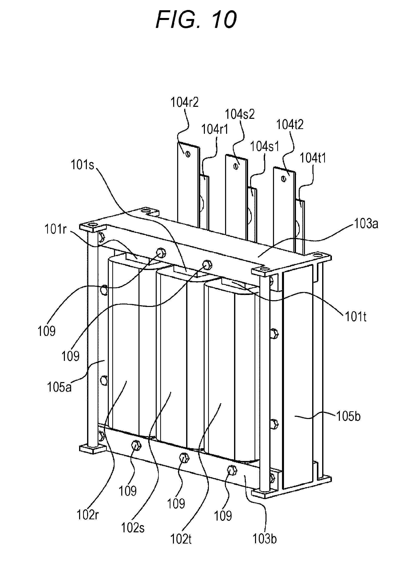
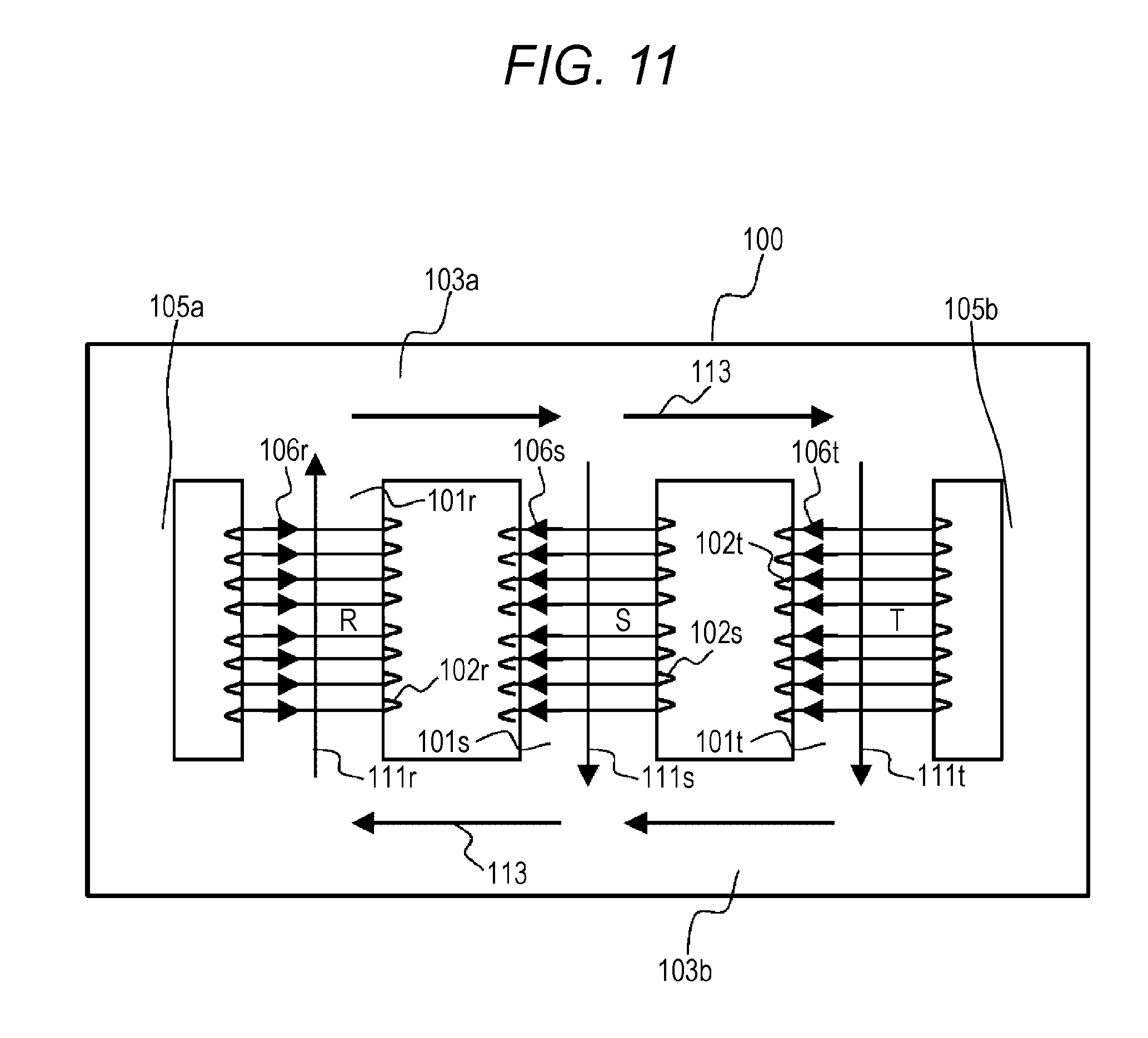
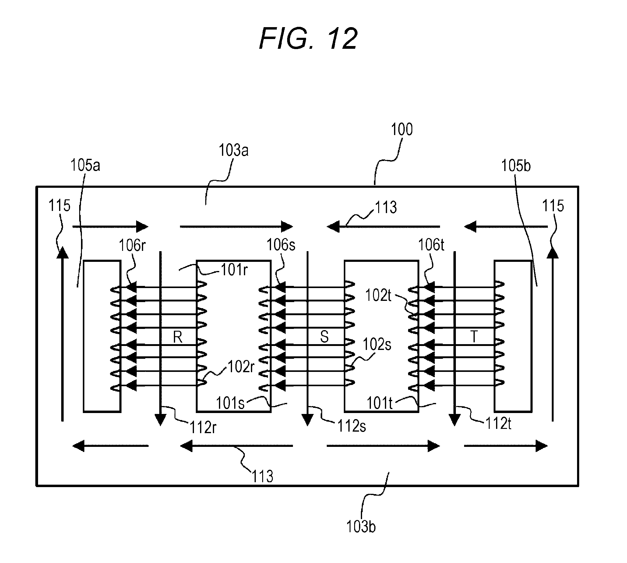
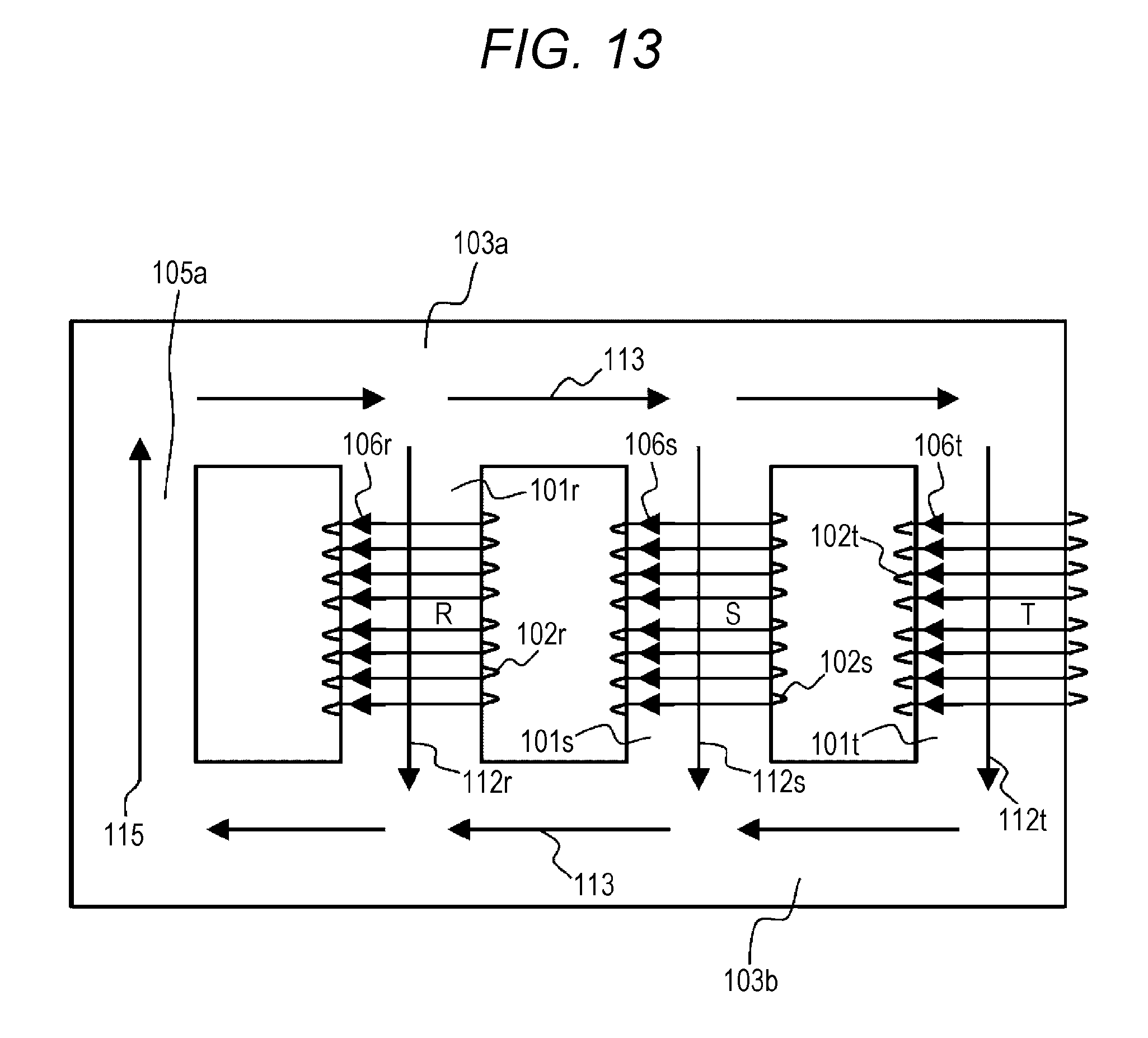
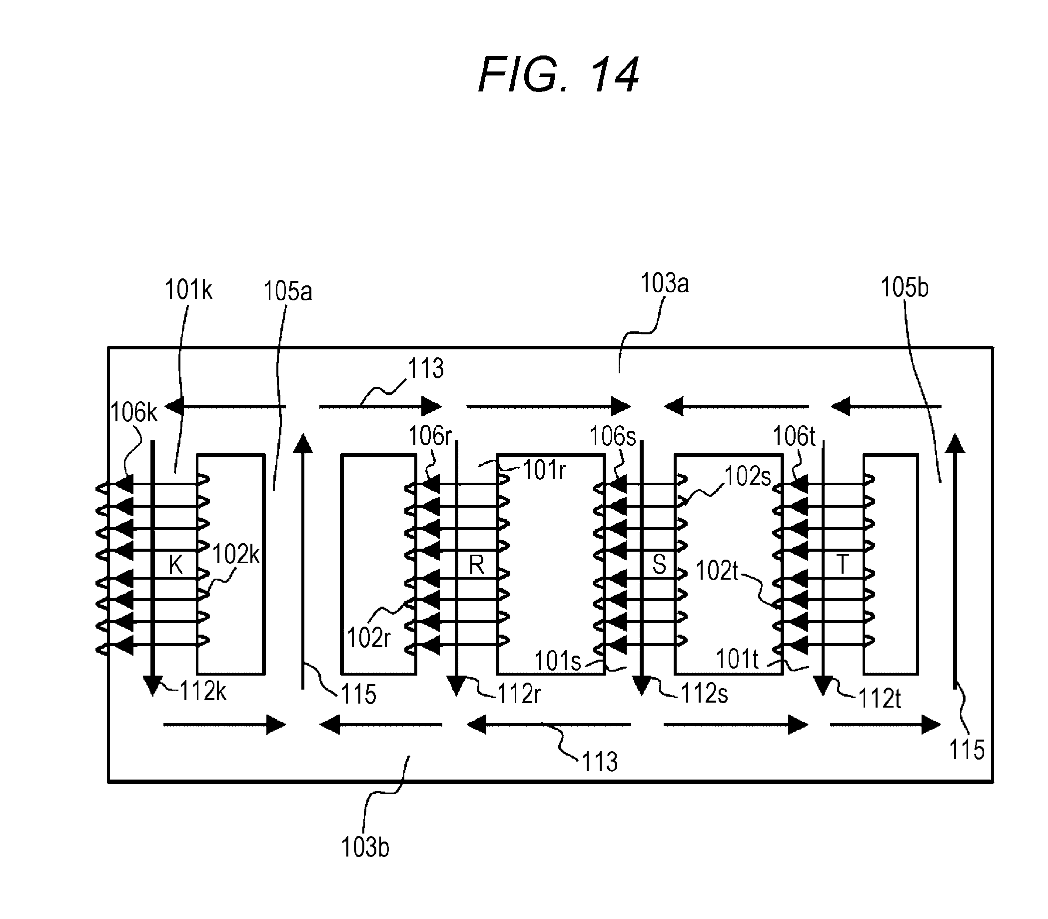
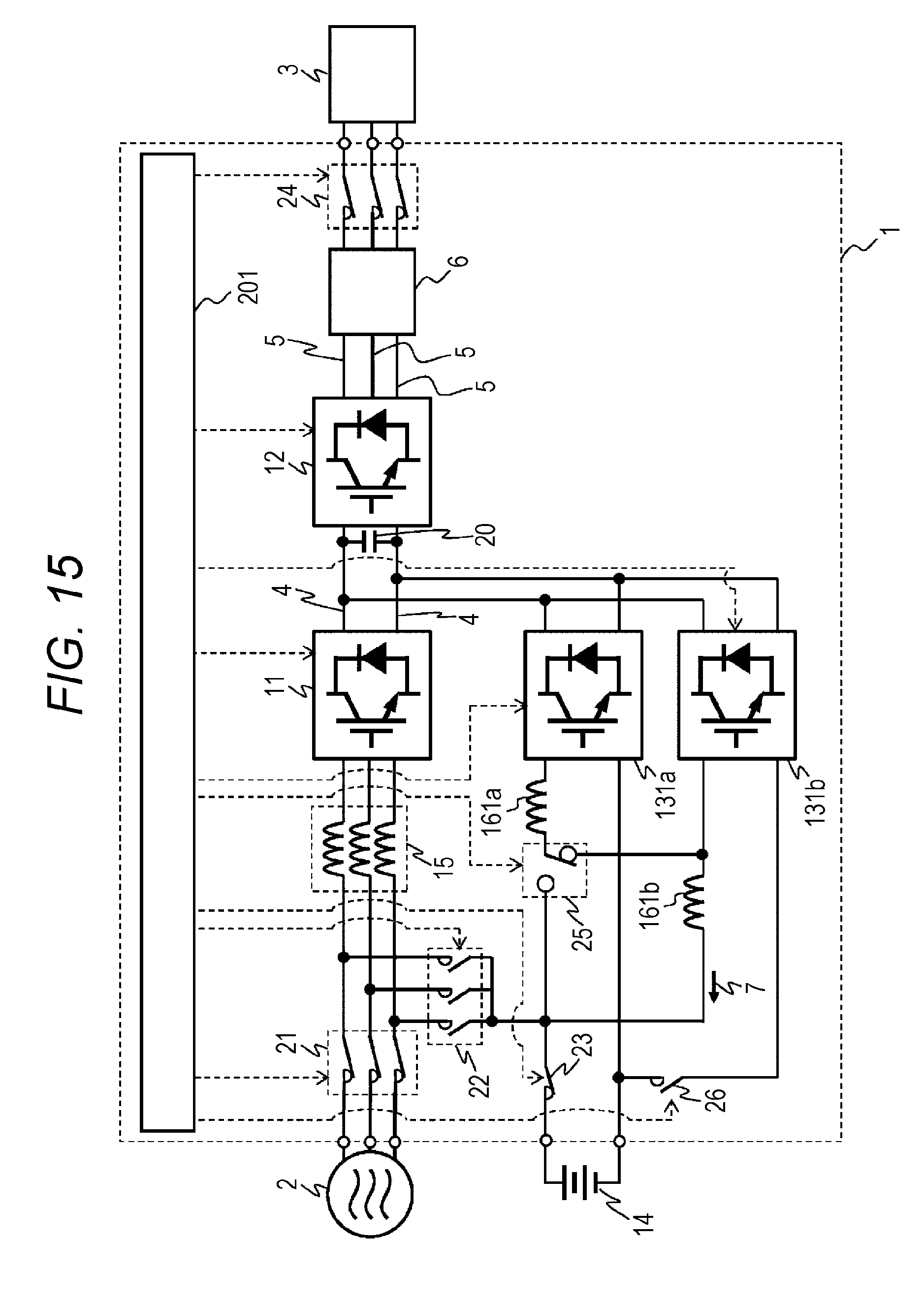
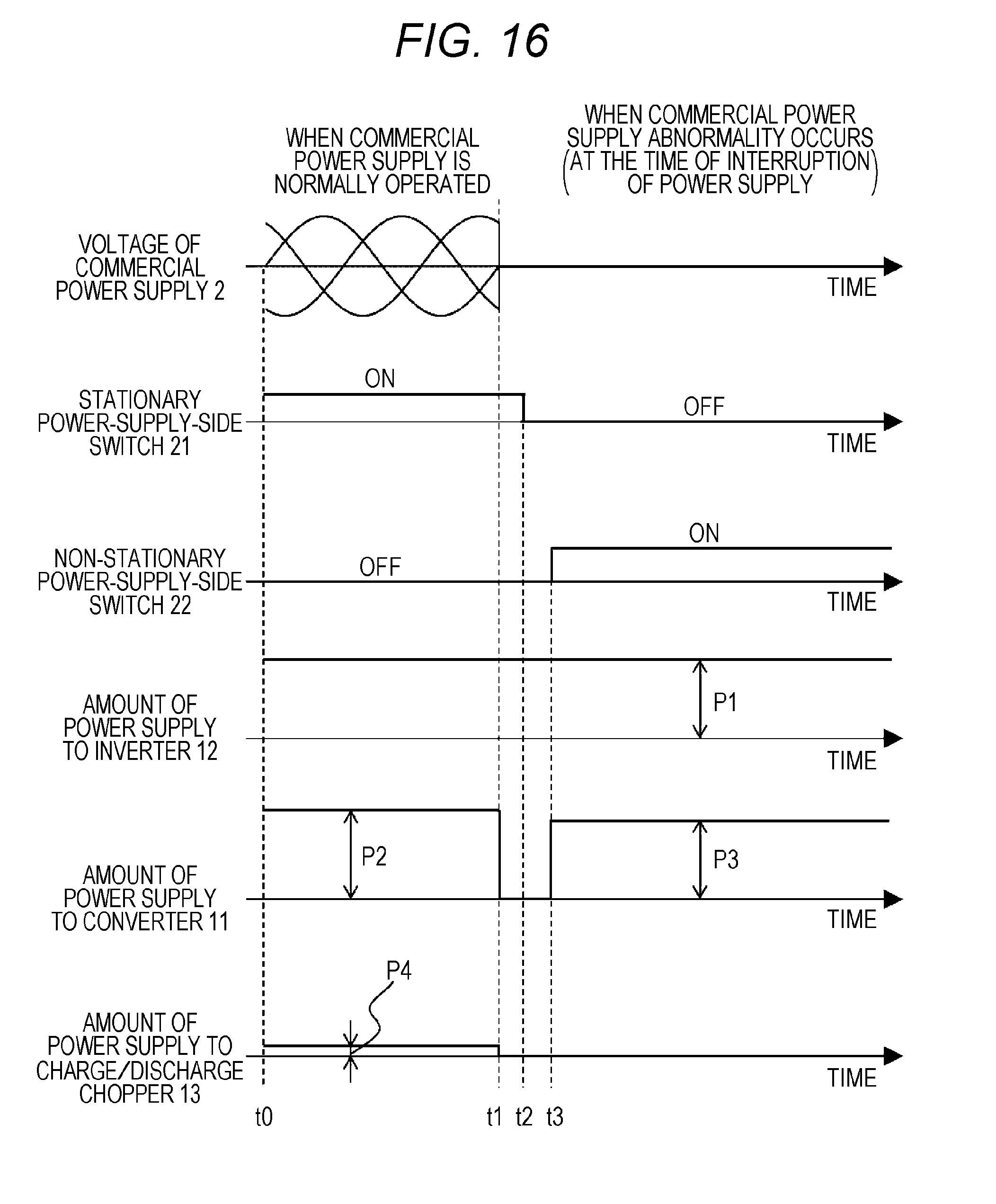
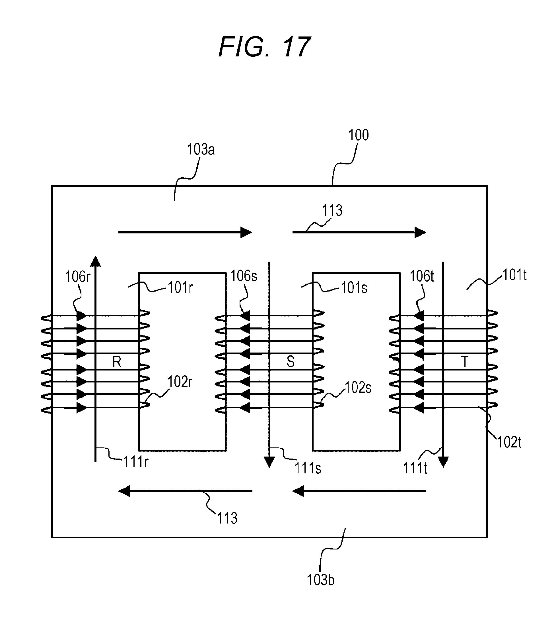
1. Field of the Invention The present invention relates to a uninterruptible power-supply system, and specifically to a uninterruptible power-supply system suitable for rectifying a three-phase AC by a converter including a power semiconductor module, converting the power into AC power of which the voltage and frequency can be changed by an inverter, and reducing a charging voltage of the storage battery or boosting a discharging voltage of the same. 2. Description of the Related Art An uninterruptible power-supply system (referred to as UPS below) is an apparatus for using a power conversion apparatus to stably supply the power without an interruption of the power supply to a load when a commercial power supply and the like which is a stationary power supply has an abnormality. As IT use has been innovated in recent years, a demand of the UPS in a data center and the like has increased. Since the UPS for the data center is laid near cities where the land price is high, it is desired to reduce an installation area, that is, to miniaturize the apparatus. The UPS is often used by using the storage battery as a voltage source when the commercial power supply and the like has an abnormality. The UPS discharges the storage battery and supplies the power to an inverter. Then, the UPS converts the power into a desired voltage and frequency and supplies it to a load. Conventionally, a chopper has a role for reducing a DC voltage rectified by the converter to charge the storage battery. The chopper also has a role for increasing a low-pressure storage battery voltage and supplying it to the inverter. The chopper is operated as a so-called bidirectional chopper (referred to as charge/discharge chopper below). Generally, in the above-mentioned charge/discharge chopper circuit, an output power at the time of charge is small. However, it is necessary to have a rated power equivalent to that of the inverter at the time of discharge. Therefore, a switching element included in the charge/discharge chopper preferably has a rated current and rated loss capable of bearing a load at the time of discharge. Accordingly, when the commercial power supply is normally operated, a power semiconductor module included in the charge/discharge chopper and a reactor in a previous stage of the charge/discharge chopper have an excessive performance. The excessive performance increases the size of a charge/discharge circuit. As a solution to a problem that the size of the charge/discharge circuit increases, for example, a system has been known in which an input connection destination of the converter is switched to the commercial power supply or the storage battery as described in JP 4951476 A. Specifically, at the time of commercial power supply abnormality, a rated DC voltage is output to the inverter by supplying the discharging power of the storage battery to the converter and the charge/discharge chopper which have performed a boosting operation. The structure described in JP 4951476 A can distribute the discharging power to the converter and the charge/discharge chopper. Therefore, miniaturization of the charge/discharge chopper itself and the reactor in the previous stage of the charge/discharge chopper can be realized. It is necessary for the conventional UPS to have three reactors in the previous stage of the converter. In order to miniaturize and mount the three reactors, a three-phase AC reactor having a three-leg iron core is used. In a structure using the reactor having the three-leg iron core, a three-phase coil is formed by respectively winding coils around magnetic leg iron cores formed by laminating thin magnetic materials. Each magnetic leg iron cores is joined to a yoke iron core. When the commercial power supply is normally operated, a magnetic flux generated by an R-phase AC voltage is formed so as to pass through the yoke iron core and flow into S-phase and T-phase magnetic legs. The magnetic fluxes generated in the S-phase and T-phase are formed so as to flow into an R-phase via the yoke iron core. The direction of the magnetic flux in each phase is determined according to the direction of a current flowing in the coil, and a magnetic circuit is closed not to leak the magnetic flux. However, when an instantaneous magnetic circuit of a case where the DC voltage is applied to the three phases of the three-phase AC reactor is described, the magnetic fluxes generated by DC energizing in each phase are formed so that a magnetic flux generated in an R-phase coil and magnetic fluxes generated in S-phase and T-phase coils flow to the same direction. Therefore, the magnetic fluxes concentrate in the yoke iron core on one side, and the magnetic fluxes become a leakage magnetic flux and form the magnetic circuit outside the structure. The leakage magnetic flux becomes a noise, and there is a possibility to cause a problem in that this causes a malfunction of a control apparatus and the like of the UPS. A purpose of the present invention is to provide an uninterruptible power-supply system which can prevent a malfunction of an apparatus control by preventing a leakage magnetic flux in a magnetic circuit formed by storage battery discharge at the time of abnormality and reducing a noise. To achieve the above purpose, in the present invention, an uninterruptible power-supply system includes a converter configured to receive a power from a three-phase AC power supply via a three-phase AC reactor and supply the power to a DC terminal by converting the power into a DC power, a capacitor configured to smooth the DC voltage supplied to the DC terminal, an inverter configured to convert the smoothed DC voltage into an AC voltage and supply the power to a load, and a charge/discharge chopper configured to reduce a voltage of the DC terminal and charge it to a storage battery or boost a voltage of the storage battery and discharge it to the DC terminal. When the three-phase AC power supply is in an abnormal state, the power from the storage battery is boosted by the charge/discharge chopper and supplied to the DC terminal, and the power from the storage battery is boosted by the converter and supplied to the DC terminal. The three-phase AC reactor includes three iron cores having three winding wires corresponding to the three phases and winding around them, a yoke iron core on one side connected to the three iron cores at one side, a yoke iron core on another side connected to the three iron cores on the another side, and a fourth iron core for connecting the yoke iron core on one side with each three iron cores. Specifically, the uninterruptible power-supply system includes the converter for converting the power from the commercial power supply into DC, the capacitor for smoothing the DC voltage converted by the converter, and the inverter for converting the DC voltage converted by the converter into an AC voltage and supply the power to the load. When the power is normally supplied from the commercial power supply, the storage battery is charged by reducing the DC voltage converted by the converter by the charge/discharge chopper. The switching unit for supplying the power of the storage battery to the converter is provided in the previous stage of the converter. When the commercial power supply is in an abnormal state, the three-phase AC converter is operated as three discharge choppers connected in parallel by supplying the power of the storage battery to the converter and boosting the power of the storage battery by the switching element included in the converter. At the same time, the power of the storage battery is boosted by the charge/discharge chopper, and a part of the discharging power is supplied. At least one three-phase AC reactor is provided in the previous stage of the converter, and the three-phase AC reactor has three coils to which the DC current from the storage battery is distributed, magnetic leg iron cores having the coils winding around them, and at least one leg which does not have a coil winding around it. The coils, the magnetic leg iron cores, and at least one leg are connected in parallel (for example, five-leg iron core). According to the present invention, when the DC voltage is applied to the three-phase AC reactor at the time of the storage battery discharge, the magnetic circuit is formed without leaking the magnetic flux in a reactor structure. Therefore, a malfunction of a control component and the like can be prevented. Embodiments of the present invention will be described below with reference to the drawings. A first embodiment of the present invention will be described with reference to A previous stage of the inverter 12 is connected to a charge/discharge chopper 13. When the commercial power supply is normally operated, the charge/discharge chopper 13 performs a circuit operation as a step-down chopper for reducing the DC voltage 4 and outputting a charging power 7 to charge a storage battery 14. A storage battery protecting switch 23 has a role for protecting a battery from an overcurrent. The charge/discharge chopper 13 and the storage battery protecting switch 23 are controlled by the signal from the host control circuit 201. Also, at the time of the commercial power supply abnormality, the discharging power 8 is transmitted to the side of the converter 11 via the non-stationary power-supply-side switch 22, and the DC voltage is applied to the three-phase AC reactor 15 having the five-leg iron core. Since a rated voltage of the inverter 12 is output when the DC voltage is input to the converter 11, the converter 11 operates as the boosting chopper similarly to the charge/discharge chopper 13. At this time, the converter 11 and the charge/discharge chopper 13 are controlled by the signal from the host control circuit 201 so that boosting operations of them are synchronized with each other. Also, According to the above, the converter 11, the inverter 12, and the charge/discharge chopper 13 mounted in the UPS 1 of the present embodiment include the two-level half bridge circuit 35 as a basic structure. The two-level half bridge circuit 35 includes the switching element 31 and the rectifier element 33 of the upper arm and the switching element 32 and the rectifier element 34 of the lower arm connected in series. When the power supplied to the load 3 exceeds the rated power of the UPS 1, the rated power is increased by increasing the number of the two-level half bridge circuits 35 of the converter 11, the inverter 12, and the charge/discharge chopper 13 connected in parallel. In the present embodiment, since the converter 11 boosts the discharging power as three boosting circuits connected in parallel at the time of the commercial power supply abnormality, the increase in the number of the circuits connected in parallel in the charge/discharge chopper 13 is smaller than that of the converter 11 or the inverter 12. First, time of t0 to t1 in a case where the commercial power supply is normally operated will be described. When the commercial power supply is normally operated, the three-phase AC is input from the commercial power supply 2, and the stationary power-supply-side switch 21 is turned ON and the non-stationary power-supply-side switch 22 is turned OFF. The power of P2 is supplied from the commercial power supply 2 to the converter 11, and the power of P1 is supplied to the inverter 12. Also, a part of the power P4 rectified by the converter 11 is supplied to the charge/discharge chopper 13 to charge the storage battery. The relationship between the amounts of the power supply when the commercial power supply is normally operated is P1=P2−P4. Next, time of t1 to t3 at the time of the commercial power supply abnormality will be described. First, the stationary power-supply-side switch 21 is turned OFF to prevent a short circuit to the commercial power supply 2 caused by the discharge of the storage battery. Time of t1 to t2 is necessary time to turn OFF the stationary power-supply-side switch 21. After it has been confirmed that the stationary power-supply-side switch 21 is turned OFF, the non-stationary power-supply-side switch 22 is turned ON. Time of t2 to t3 is necessary time to turn ON the non-stationary power-supply-side switch 22. Between the times t1 and t3, although the power supply to the converter 11 is interrupted, it is necessary for the UPS 1 to supply the power to the load 3 without instantaneous interruption. Therefore, the discharge of the storage battery is started in parallel to the ON/OFF operations of the switches 21 and 22, and the charge/discharge chopper 13 starts the boosting operation. The charge/discharge chopper 13 independently performs the boosting circuit operation between the times t1 and t3. However, since the charge/discharge chopper 13 has a smaller constant rating than that of the inverter 12, it is necessary to perform an overload operation for a short time. At the time of the overload operation, the DC power which receives the power of P5 and is boosted by the charge/discharge chopper 13 is supplied to the inverter 12. Therefore, the relationship between the amounts of the power supply of the time t1 to t3 is P1=P5. Next, at and after the time t3 at the time of the commercial power supply abnormality will be described. When the non-stationary power-supply-side switch 22 is turned ON, the discharging power 8 of the storage battery 14 is distributed to the converter 11. The converter 11 performs a boosting circuit operation by sending a signal for abnormal condition from the control circuit 202 to the switching elements 31 and 32 included in the converter 11. At and after the time t3, the converter 11 and the charge/discharge chopper 13 become four boosting circuits connected in parallel of the storage battery 14. In the present embodiment, the converter 11 has a load of the power P3, and the amount of the power supply of the charge/discharge chopper 13 falls to P6 which is a constant rating at the abnormal condition. According to the rectifying function of the converter 11, it can be considered that the rated power is larger than that of the charge/discharge chopper 13. Even when the relationship between the amounts of the power supply is P3>P6, the converter 11 is sufficiently operated. The DC power boosted by the converter 11 and the charge/discharge chopper 13 is sent to the inverter 12, and the power is converted form DC to AC. After that, the power P1 is supplied to the load 3. The relationship between the amounts of the power supply at this time is P1=P3+P6. The time of t5 when the commercial power supply is restored to the time t7 will be described. First, the non-stationary power-supply-side switch 22 is turned OFF to prevent the short circuit to the commercial power supply 2 caused by the discharge of the storage battery. Time of t5 to t6 is necessary time to turn OFF the non-stationary power-supply-side switch 22. After it has been confirmed that the non-stationary power-supply-side switch 22 is turned OFF, the stationary power-supply-side switch 21 is turned ON. Time of t6 to t7 is necessary time to turn ON the stationary power-supply-side switch 21. Between the times t6 and t7, although the power supply to the converter 11 is interrupted, it is necessary for the UPS 1 to supply the power to the load 3 without instantaneous interruption. Therefore, the charge/discharge chopper 13 becomes the overload operation from the time t6 to t7 and receives the power P5. The DC power boosted by the charge/discharge chopper 13 is supplied to the inverter 12 and converted into a desired voltage and frequency. After that, the converted power is supplied to the load 3. The relationship between the amounts of the power supply of the time t6 to t7 is P1=P5. At and after the time t7 when the stationary power-supply-side switch 21 is turned ON, the UPS 1 performs the operation of a case where the commercial power supply is normally operated. When the commercial power supply is normally operated, the converter 11 performs the rectifier circuit operation and converts the AC power of the commercial power supply into the DC power. Also, the voltage of the DC power converted by the converter 11 is reduced by a step-down circuit operation of the charge/discharge chopper 13, and the storage battery 14 is charged. In this way, even when the commercial power supply abnormality occurs, the power can be stably supplied to the inverter 12. With the present embodiment, the charge/discharge chopper 13 has a smaller constant rating than that of the inverter 12. Therefore, it contributes to miniaturize the apparatus. Before describing a structure having characteristics of the present embodiment, a three-phase AC reactor formed as a three-leg iron core will be described as an example which is a reference example and is in contrast to the present embodiment. In a schematic structural diagram of the three-phase AC reactor having the three-leg iron core illustrated in The instantaneous magnetic circuit of a case where the DC voltage is applied to the three phases of the three-phase AC reactor having the three-leg iron core is illustrated in Next, as a five-leg iron core which is a characteristic of the present embodiment, On the other hand, A second embodiment of the present invention will be described with reference to Next, a third embodiment of the present invention will be described with reference to A fourth embodiment of the present invention will be described with reference to A fifth embodiment of the present invention will be described with reference to When the power is normally supplied from the commercial power supply, the storage battery is charged by reducing the DC voltage by the charge/discharge chopper. The switching unit is provided in the previous stage of the converter. When the commercial power supply is in an abnormal state, the three-phase AC converter is operated as three discharge choppers connected in parallel by supplying the power of the storage battery to the converter and boosting the power by the switching element included in the converter. The power of the storage battery is boosted by the charge/discharge chopper, and a part of the discharging power is supplied. One three-phase AC reactor is provided in the previous stage of the converter, and the three-phase AC reactor has three coils, magnetic leg iron cores having the coils winding around them, and one leg without a coil winding around it connected in parallel. 1. An uninterruptible power-supply system comprising:
a converter configured to receive a power from a three-phase AC power supply via a three-phase AC reactor and supply the power to a DC terminal by converting the power into a DC power; a capacitor configured to smooth a DC voltage supplied to the DC terminal; an inverter configured to convert the smoothed DC voltage into an AC voltage and supply the power to a load; and a charge/discharge chopper configured to reduce a voltage of the DC terminal and charge it to a storage battery or boost a voltage of the storage battery and discharge it to the DC terminal, wherein when the three-phase AC power supply is in an abnormal state, the power from the storage battery is boosted by the charge/discharge chopper and supplied to the DC terminal, and the power from the storage battery is boosted by the converter and supplied to the DC terminal, and the three-phase AC reactor includes three iron cores having three winding wires corresponding to the three phases and winding around them, a yoke iron core on one side connected to the three iron cores at one side, a yoke iron core on another side connected to the three iron cores on the another side, and a fourth iron core for connecting the yoke iron core on one side with each three iron cores. 2. The uninterruptible power-supply system according to the fourth iron core connects the yoke iron core on one side with the yoke iron core on the another side. 3. The uninterruptible power-supply system according to a fifth iron core configured to connect the yoke iron core on one side with the yoke iron core on the another side. 4. The uninterruptible power-supply system according to the three iron cores have magnetic fluxes for flowing to the same direction when the three-phase AC power supply is in the abnormal state. 5. The uninterruptible power-supply system according to the charge/discharge chopper includes a smaller constant rating than that of the inverter. 6. The uninterruptible power-supply system according to a switching unit configured to supply the power of the storage battery to the converter; and a control apparatus configured to limit a discharging power of the chopper equal to or less than the constant rating of the chopper after switching, wherein the chopper supplies the rated power of the inverter to the inverter during a switching time of the switching unit. 7. The uninterruptible power-supply system according to two or more charge/discharge choppers are connected in parallel, the charge/discharge chopper includes a single-phase reactor connected to each previous stage of the chopper and a switching unit for changing a current path between the time of the charge/discharge the storage battery provided therein and changes an inductance of the current path between the time of the charging and discharging. 8. The uninterruptible power-supply system according to the three-phase AC reactor in the previous stage of the converter and a single-phase reactor in the previous stage of the charge/discharge chopper are integrated into a single reactor, and the reactor has four magnetic leg iron cores having coils winding around them and at least one leg which does not have a coil winding around it, and the four magnetic leg iron cores and at least one leg are connected in parallel (for example, six-leg iron core). 9. The uninterruptible power-supply system according to a switching unit configured to supply the power of the storage battery to the converter, wherein the capacitor supplies a rated power of the inverter to the inverter during a switching time of the switching unit, and a constant rating of the charge/discharge chopper is determined according to the power to charge the storage battery. BACKGROUND OF THE INVENTION
SUMMARY OF THE INVENTION
BRIEF DESCRIPTION OF THE DRAWINGS
DESCRIPTION OF THE PREFERRED EMBODIMENTS
First Embodiment
Second Embodiment
Third Embodiment
Fourth Embodiment
Fifth Embodiment