CARRIER FOR FLEXIBLE PRINTED CIRCUIT
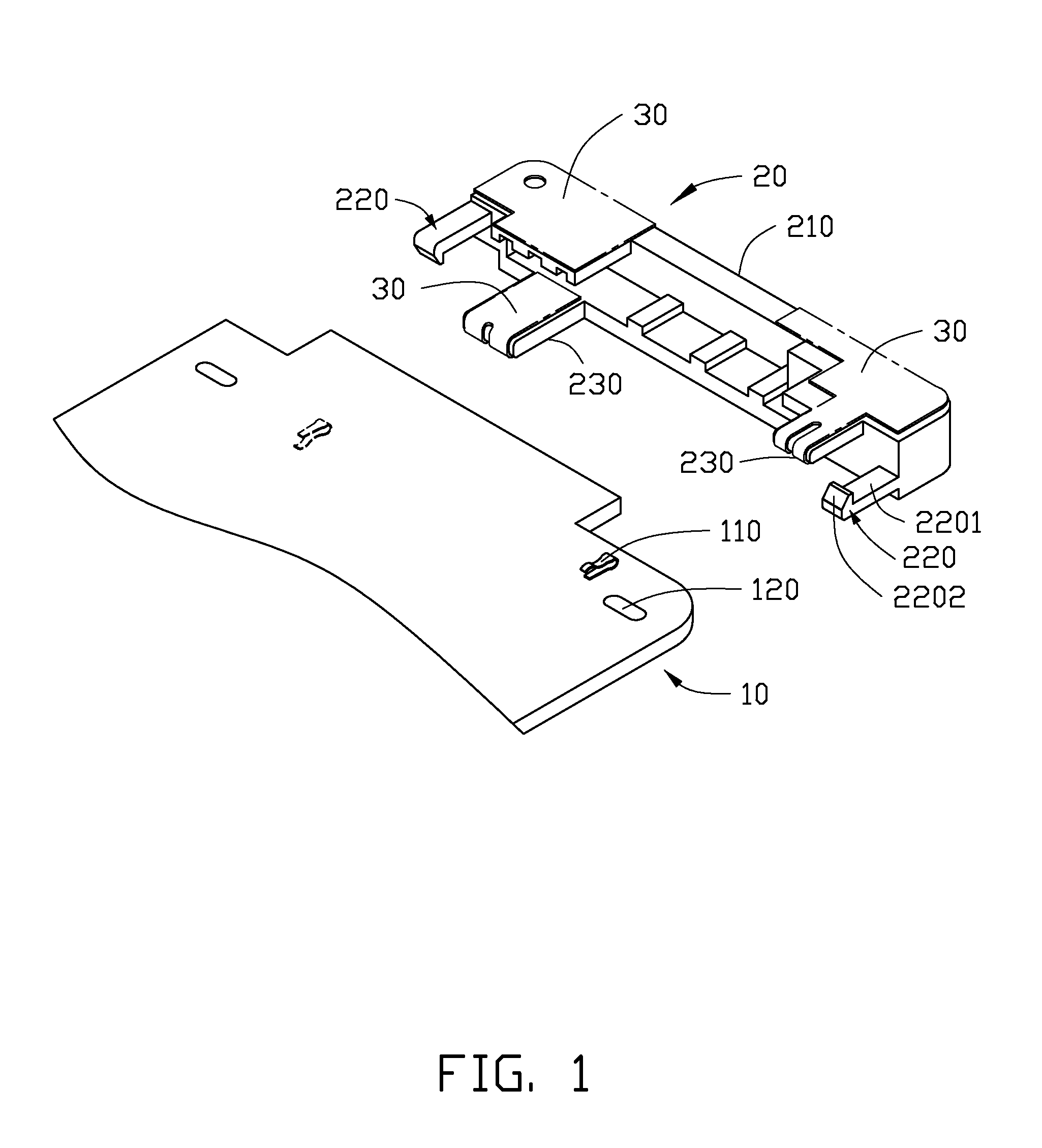
The present disclosure generally relates to flexible printed circuits (FPCs), and more particularly to a carrier to connect an FPC to a printed circuit board (PCB). Flexible printed circuits (FPCs) are used in a variety of electronic devices. The FPCs can be connected to printed circuit boards (PCBs) of the electronic devices. Implementations of the present technology will now be described, by way of example only, with reference to the attached figures. It will be appreciated that for simplicity and clarity of illustration, where appropriate, reference numerals have been repeated among the different figures to indicate corresponding or analogous elements. In addition, numerous specific details are set forth in order to provide a thorough understanding of the embodiments described herein, However, it will be understood by those of ordinary skill in the art that the embodiments described herein can be practiced without these specific details. In other instances, methods, procedures and components have not been described in detail so as not to obscure the related relevant feature being described. Also, the description is not to be considered as limiting the scope of the embodiments described herein. The drawings are not necessarily to scale and the proportions of certain parts have been exaggerated to better illustrate details and features of the present disclosure. Definitions that apply throughout the disclosure will now be presented. The references “a plurality of” and “a number of” mean “at least two.” The term “comprising,” when utilized, means “including, but not necessarily limited to”; it specifically indicates open-ended inclusion or membership in the so-described combination, group, series, and the like. The carrier 20 can include a main body 210 and a plurality of contacting members 230. In at least one embodiment, there are two contacting members 230 extending from the main body 210. A first contacting member 230 can extend from an upper portion of the main body 210, and a second contacting member 230 can extend from a lower portion of the main body 210. A portion of the FPC 30 can be located on a bottom surface of the first contacting member 230, and another portion of the FPC 30 can be located on a top surface of the second contacting member 230. A plurality of resilient latching members 220 can extend from the main body 210 of the carrier 20. In at least one embodiment, there are two latching members 220. A first latching member 220 can extend from the upper portion of the main body 210, and a second latching member 220 can extend from the lower portion of the main body 210. Each latching member 220 can include a latching portion 2201 and a hooked portion 2202. The latching portion 2201 can extend from the main body 210, and the hooked portion 2202 can extend from the latching portion 2201. In at least one embodiment, a distance between the two latching portions 2201 is substantially equal to a thickness of the PCB 10. In at least one embodiment, the first contacting member 230 and the second latching member 220 can be located adjacent to one side of the main body 210, and the second contacting member 230 and the first latching member 220 can be located adjacent to another side of the main body 210. The PCB 10 can include a plurality of elastic pieces 110 corresponding to the plurality of contacting members 230. In at least one embodiment, there are two elastic pieces 110. A first elastic piece 110 is located on a top surface of the PCB 10, and a second elastic piece 110 is located on a bottom surface of the PCB 10. The PCB 10 can define a plurality of holes 120 corresponding to the plurality of latching members 220. In at least one embodiment, the PCB 10 defines two holes 120, and each hole 120 is a through hole. When the carrier 20 is secured to the PCB 10, the first elastic piece 110 contacts the portion of the FPC 30 located on the bottom surface of the first contacting member 230, and the second elastic piece 110 contacts the portion of the FPC 30 located on the top portion of the second contacting member 230. The elastic pieces 110 can electrically connect the FPC 30 to the PCB 10. Furthermore, the carrier 20 is firmly secured to the PCB 10 such that the carrier 20 is prevented from moving relative to the PCB 10. Referring to In another embodiment, the holes 120 can be blind holes, such that a first hole 120 is defined in the top surface of the PCB 10, and a second hole 120 is defined in the bottom surface of the PCB 10. The hooked portion of the first latching member 220 can insert into the first hole 120, and the hooked portion of the second latching member 220 can insert into the second hole 120. In the present disclosure, the carrier 20 can be secured to the PCB 10 easily by the latching members 220. Thus, additional securing components, such as screws, are not needed. Because the carrier 20 is not made of metal and does not require other metal components to be secured to the PCB 10, signal interference between the carrier 20 and electronic components, such as an antenna, is prevented. The embodiments shown and described above are only examples. Many details are often found in the art. Therefore, many such details are neither shown nor described. Even though numerous characteristics and advantages of the present technology have been set forth in the foregoing description, together with details of the structure and function of the present disclosure, the disclosure is illustrative only, and changes may be made in the detail, including in matters of shape, size, and arrangement of the parts within the principles of the present disclosure, up to and including the full extent established by the broad general meaning of the terms used in the claims. It will therefore be appreciated that the embodiments described above may be modified within the scope of the claims. A carrier for a flexible printed circuit (FPC) includes a number of latching members. The latching members secure the carrier to a printed circuit board (PCB). 1. A carrier for a flexible printed circuit (FPC) comprising a plurality of latching members, wherein the plurality of latching members secure the carrier to a printed circuit board (PCB). 2. The carrier as described in 3. The carrier as described in 4. The carrier as described in 5. The carrier as described in 6. The carrier as described in 7. The carrier as described in 8. The carrier as described in 9. The carrier as described in 10. The carrier as described in 11. The carrier as described in 12. The carrier as described in 13. The carrier as described in 14. The carrier as described in 15. The carrier as described in 16. The carrier as described in 17. The carrier as described in 18. The carrier as described in 19. The carrier as described in 20. The carrier as described in FIELD
BACKGROUND
BRIEF DESCRIPTION OF THE DRAWINGS
DETAILED DESCRIPTION