PREFORM INJECTION MOLDING DEVICE
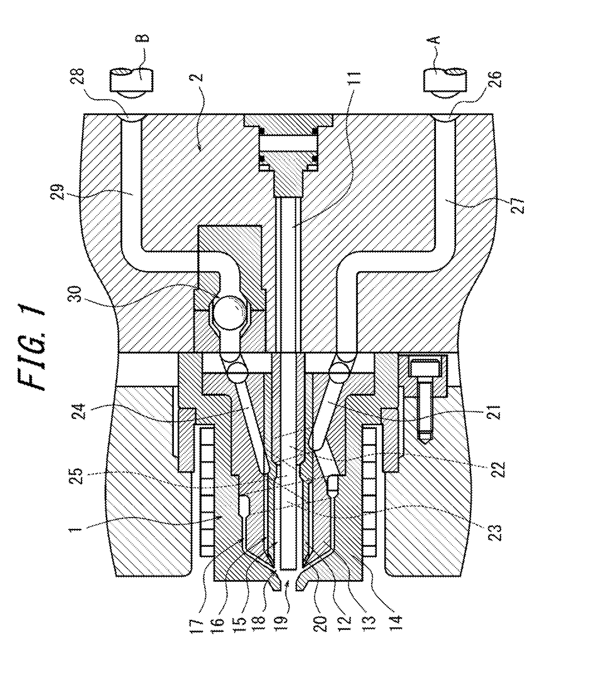
The present disclosure relates to a device for injection molding a preform subject to biaxial stretch blow molding, and especially to a nozzle used in a device for injection molding a preform in which an intermediate layer made of an intermediate-layer resin is laminated between substrate layers made of a main resin. Biaxially stretched blow molded bottles made of Polyethylene Terephthalate (hereinafter, abbreviated as PET) are used in various fields, such as beverages, foods, cosmetics, and so forth. Especially, bottles for use in applications demanding a gas barrier property are made by laminating an intermediate layer made of a gas barrier resin, such as a nylon-based resin and an ethylene-vinyl alcohol copolymer, with substrate layers made of a PET resin as the main resin, in a manner such that the intermediate layer is embedded therebetween. Patent Literature 1 describes a process of molding a laminated preform, which is a primary molded product used in biaxial stretch blow molding of a laminated bottle in which an intermediate layer made of a nylon resin is laminated between substrate layers made of a PET resin. In such biaxially stretched blow molded bottles, although the substrate layers are in tight contact with the intermediate layer, these two layers are in many cases not adhered to each other due to a difference in the materials. Accordingly, the two layers might be partially delaminated under the action of shearing force caused by an impact of dropping or the like. Once the partial delamination as described above occurs in the layers of a bottle used for, for example, a carbonated drink, carbon dioxide gas permeates an inner layer of the PET resin and enters the delaminated portion. The resulting pressure of carbon dioxide gas further exacerbates the delamination until the delamination is visible in external appearance when light is scattered or reflected from the delaminated interface, which ruins the appearance. In this connection, the present inventors have proposed in Patent Literature 2 a laminated bottle by which the aforementioned problem of delamination in a bottle including an intermediate layer is solved. In detail, In Patent Literature 2, the present inventors have also proposed a preform subject to biaxial stretch blow molding to be molded into the aforementioned laminated bottle and a device for injection molding the preform. In detail, Meanwhile, during use of the aforementioned injection molding device, since the middle flow channel 316 is segmented into the small streams by the vertical blocking rib pieces 316R and since the flow of the corresponding molten resin is inevitably interrupted under the effect of the vertical blocking rib pieces 316R, the molten resin sometimes partially remains in the flow channel. When, in this situation, molding is conducted successively, the temperature of the built-up resin might increase, resulting in resin burning (carbonization). The carbonized resin might get mixed in the preform as impurities. Furthermore, when adhering to side walls of the vertical blocking rib pieces 316R or onto a wall surface of the lower end portion of the inner ring mandrel 324 Moreover, at the confluence 318 in the nozzle section 311, flow of each molten resin changes depending on the rate of another molten resin that has passed through a different channel and on differences on directions of the resins flowing into the confluence 318. Accordingly, the main resin might affect and greatly change the streams of the intermediate layer resin into which the intermediate layer resin has been segmented by the vertical blocking rib pieces 316R, possibly resulting in changes in the shapes (width, thickness, and the like) of the intermediate layer 113 and vertical connecting zones 114 beyond an allowable tolerance. The present disclosure is to solve the above problems, and the present disclosure is to provide an improved injection molding device that is capable of forming the intermediate layer and the vertical connecting zones of the preform into desired shapes and dimensions. One of aspects of the present disclosure resides in an injection molding device that injection molds a preform which is subjected to biaxial stretch blow molding and which includes at least one intermediate layer laminated between substrate layers. The injection molding device includes a nozzle section through which a main resin used to form the substrate layers and an intermediate layer resin used to form the intermediate layer are injected. The nozzle section includes at least three cylindrical layer-forming flow channels disposed coaxially, the three cylindrical layer-forming flow channels including an inner flow channel and an outer flow channel, which are used to form the substrate layers each made of the main resin, and a middle flow channel, which is located between the inner flow channel and the outer flow channel and is used to form the intermediate layer made of the intermediate layer resin. The middle flow channel is segmented into a predetermined number of flow sub-channels by at least one vertical blocking rib piece disposed transversely within the middle flow channel on a downstream side thereof. Herein, (i) the vertical blocking rib piece has a pair of side walls located on both sides of the vertical blocking rib piece in a circumferential direction, and the pair of side walls each include a side wall's upstream portion located on an upstream side, the side wall's upstream portions being formed as angled surfaces whose distance from each other decreases from the downstream side to the upstream side, and/or (ii) an end portion of the vertical blocking rib piece that is located on the downstream side is tucked in at least one of the inner flow channel and the outer flow channel. In the injection molding device according to one of preferred embodiments, the at least one vertical blocking rib piece includes a plurality of vertical blocking rib pieces, and the pair of side walls each further include a side wall's downstream portion located on the downstream side, and a side clearance between the side wall's downstream portions included in any two adjacent vertical blocking rib pieces is constant from the upstream side to the downstream side. In the injection molding device according to another preferred embodiment, the end portion of the vertical blocking rib piece that is located on the downstream side is tucked at least in the outer flow channel. In the injection molding device according to yet another preferred embodiment, (i) the vertical blocking rib piece has the pair of side walls located on both sides of the vertical blocking rib piece in the circumferential direction, and the pair of side walls each include the side wall's upstream portion located on the upstream side, the side wall's upstream portions being formed as angled surfaces whose distance from each other decreases from the downstream side to the upstream side, and (ii) the end portion of the vertical blocking rib piece that is located on the downstream side is tucked in at least one of the inner flow channel and the outer flow channel. In the injection molding device according to yet another preferred embodiment, the nozzle section includes an inner ring mandrel including inside thereof the inner flow channel, a middle ring mandrel surrounding the inner ring mandrel and including the middle flow channel between the middle ring mandrel and the inner ring mandrel, and an outer ring mandrel surrounding the middle ring mandrel and including the outer flow channel between the outer ring mandrel and the middle ring mandrel, and at least the inner ring mandrel is coated with a repellency-enhancing film. In the injection molding device according to yet another preferred embodiment, the film applied to the inner ring mandrel includes a titanium nitride (TiN) film or a NiP/PTFE film containing nickel phosphide (NiP) and polytetrafluoroethylene (PTFE). In the injection molding device according to yet another preferred embodiment, a base material of the inner ring mandrel includes stainless. When the vertical blocking rib piece herein has the pair of side walls located on both sides of the vertical blocking rib piece in the circumferential direction, and the pair of side walls each include the side wall's upstream portion located on the upstream side, the side wall's upstream portions being formed as angled surfaces whose distance from each other decreases from the downstream side to the upstream side, flow of the intermediate layer resin is prevented from being interrupted by the vertical blocking rib piece. Furthermore, when the end portion of the vertical blocking rib piece that is located on the downstream side is tucked in at least one of the inner flow channel and the outer flow channel, a change in flow of the intermediate layer resin is limited even after the intermediate layer resin has joined with the main resin. Thus, according to the present disclosure, flow of the intermediate layer resin is stabilized, and accordingly, the intermediate layer and the vertical connecting zones are formed into desired shapes and dimensions. In the accompanying drawings: The following describes an injection molding device according to preferred embodiments of the present disclosure in detail with reference to the drawings. In The nozzle section 1 includes a cylindrical shut-off pin 11 disposed at center and also includes an inner ring mandrel 12, a middle ring mandrel 13, and an outer ring mandrel 14 that have a cylindrical shape and are disposed in this order coaxially about the shut-off pin 11. With the above structure, three layer-forming flow channels are formed in total. That is to say, a cylindrical inner flow channel 15 (which is also columnar in a region thereof that is above a tip of the shut-off pin 11) for flow of the main resin used to form an inner layer of the preform is formed between the shut-off pin 11 and the inner ring mandrel 12. A cylindrical middle flow channel 16 for flow of the intermediate layer resin used to form an intermediate layer of the preform is also formed between the inner ring mandrel 12 and the middle ring mandrel 13. An outer flow channel 17 for flow of the main resin used to form an outer layer of the preform is also formed between the middle ring mandrel 13 and the outer ring mandrel 14. The middle flow channel 16 and the outer flow channel 17 have end portions on the downstream side where these channels are reduced in diameter to form a tapered cylindrical channel portion. Further downstream of the tapered cylindrical channel portion, a cylindrical joining flow channel 19 is formed, via a confluence 18 where the resins having passed the layer-forming flow channels join together. In the tapered cylindrical channel portion, vertical blocking rib pieces 20 are disposed transversely within the middle flow channel 16 to segment the middle flow channel 16 into the same number of flow sub-channels as the number of the vertical blocking rib pieces 20. In the present embodiment, as illustrated in Herein, as illustrated in Furthermore, the pair of side walls 20 As illustrated in On the other hand, the hot runner block 2 mounted on the upstream side of the nozzle section 1 is provided with a supply port 26 for introduction of the main resin that has been supplied from the resin supply unit A and a hot runner 27 connecting the supply port 26 and the aforementioned introduction channel 21. The hot runner block 2 is further provided with a supply port 28 for introduction of the intermediate layer resin that has been supplied from the resin supply unit B and a hot runner 29 connecting the supply port 28 and the aforementioned introduction channel 24. Further downstream of the hot runner 29, there is also provided a check valve 30 having a backflow prevention function using a ball valve to start and stop supply of the intermediate layer resin immediately with high precision. Additionally, the check valve 30 may also be provided in the nozzle section 1. To mold a preform with use of the injection molding device structured as above, one may introduce the molten main resin to the supply port 26 from the resin supply unit A and introduce the molten intermediate layer resin to the supply port 28 from the resin supply unit B. By doing so, the molten main resin passes along the hot runner 27 and the introduction channel 21 and then, is divided by the manifolds 22 and 23 to be introduced to the inner flow channel 15 and the outer flow channel 17. On the other hand, when the check valve 30 is open, the molten intermediate layer resin passes along the hot runner 29 and the introduction channel 24 and then, is introduced to the middle flow channel 16 through the manifold 25. Herein, as illustrated in Furthermore, as illustrated in Then, as illustrated in Additionally, although in the example of The following describes an injection molding device according to the second embodiment of the present disclosure with reference to To mold a preform by using the injection molding device according to the second embodiment, one may similarly introduce the molten main resin to the supply port 26 from the resin supply unit A and introduce the molten intermediate layer resin to the supply port 28 from the resin supply unit B as illustrated in Similarly to the first embodiment, after being segmented into eight streams in the circumferential direction by the vertical blocking rib pieces 20, the intermediate layer resin b flows toward the confluence 18 as illustrated in The injection molding device according to the present disclosure is not limited to the above embodiments and may include many variations. For example, although in the above embodiments the vertical blocking rib pieces 20 are disposed in the tapered portion of the inner ring mandrel 12, the vertical blocking rib pieces 20 may be further extended toward the upstream side even to the cylindrical outer circumferential surface of the inner ring mandrel 12. Furthermore, as illustrated in In the injection molding devices according to the first and second embodiments, the inner ring mandrel 12 may be coated with a repellency-enhancing film. Although the middle flow channel 16 is segmented into the narrow flow sub-channels by the vertical blocking rib pieces 20, use of the film prevents built-up of the molten resin in the flow channel, thereby reducing occurrence of resin burning effectively. Preferred examples of the repellency-enhancing film include a titanium nitride (TiN) film and a NiP/PTFE film containing nickel phosphide (NiP) and polytetrafluoroethylene (PTFE). Especially, a TiN film is superior in terms of durability due to its higher hardness compared with a NiP/PTFE film. As a base material of the inner ring mandrel 12, stainless is preferably used. Although the middle flow channel 16, having been narrowed by the vertical blocking rib pieces 20, is subject to high pressure while the molten resin flows therein, stainless provides excellent durability due to its high hardness. The same inner ring mandrels as the inner ring mandrel illustrated in After molding of each preform, the nozzle section was disassembled to observe the inner ring mandrel. A foreign substance, which appeared to be the carbonized resin, was found adhered between adjacent vertical blocking rib pieces (i.e., flow sub-channels of the intermediate layer resin) both in the inner mandrel that is not coated with a film and the inner ring mandrel coated with the hard chrome film. On the other hand, no such foreign substance was found adhered in the inner ring mandrel coated with the TiN film and the inner ring mandrel coated with the NiP/PTFE film. Thus, the inner ring mandrel coated with the TiN film and the inner ring mandrel coated with the NiP/PTFE film are considered to be capable of preventing occurrence of carbonization of the resin, or, capable, even when carbonization of the resin occurs, of allowing the carbonized resin to be eliminated by ejection (purging). The results of observation of the inner ring mandrels and the results shown in Table 1 clearly indicate that, with use of the inner ring mandrel coated with the TiN film and the inner ring mandrel coated with the NiP/PTFE film, the intermediate layer and the vertical connecting zones may be formed into desired shapes and dimensions. Additionally, a repellency-enhancing film may be applied not only to the inner ring mandrel but also to the middle ring mandrel and the outer ring mandrel. Especially, applying a film to the middle ring mandrel, which forms the middle flow channel between itself and the inner ring mandrel, will facilitate flow of the intermediate layer resin, and accordingly, it is better ensured that deformation of the intermediate layer due to occurrence of resin burning will be prevented. Furthermore, although in the above embodiments the nozzle section is configured to form a preform having a lamination configuration including the three layers made of the two different types of resins, a preform having any different lamination configuration, including four layers made of the two different types of resins, and four layers made of three different types of resins, may be formed by providing the nozzle section with an additional flow channel as needed. Moreover, the number of the vertical blocking rib pieces 20 may be changed appropriately in accordance with a desired number of the vertical connecting zones, and only a single and not a plurality of vertical blocking rib piece may also be disposed. Moreover, the first embodiment and the second embodiment may be combined. The injection molding device according to the present disclosure allows formation of the intermediate layer having a desired shape and dimension even when preform injection molding is conducted successively. Accordingly, preforms of excellent quality are molded, and moreover, production efficiency is improved because of reduced clogging in the nozzle section. 1 nozzle section 2 hot runner block 11 shut-off pin 12 inner ring mandrel 12 13 middle ring mandrel 13 14 outer ring mandrel 15 inner flow channel 16 middle flow channel 17 outer flow channel 18 confluence 19 joining flow channel 20 vertical blocking rib piece 20 20 20 20 20 21 introduction channel 22, 23 manifold 24 introduction channel 25 manifold 26 supply port 27 hot runner 28 supply port 29 hot runner 30 check valve A resin supply unit B resin supply unit a flow of main rein in inner flow channel b flow of intermediate layer rein in middle flow channel c flow of main rein in outer flow channel h height difference between inner circumferential end of middle ring mandrel and inner circumferential end of vertical blocking rib piece s side clearance 101 preform 102 neck 103 neck ring 105 body 106 bottom 111 substrate layer 111 111 113 intermediate layer 114 vertical connecting zone 201 bottle 202 neck 203 neck ring 204 shoulder 205 body 206 bottom 211 substrate layer 211 211 213 intermediate layer 214 vertical connecting zone 301 mold 311 nozzle section 315 inner flow channel 316 middle flow channel 316R vertical blocking rib piece 317 outer flow channel 318 confluence 319 joining flow channel 320 shut-off pin 324 324 324 An injection molding device including a middle flow channel which forms an intermediate layer of a preform which is subject to biaxial stretch blow molding. The middle flow channel s segmented into a predetermined number of flow sub-channels by vertical blocking rib piece(s). Side wall's upstream portions of the vertical blocking rib piece are formed as angled surfaces whose distance from each other decreases from the downstream side to the upstream side, and/or, an end portion of the vertical blocking rib piece that is located on the downstream side is tucked in at least one of the inner flow channel and the outer flow channel. 1. An injection molding device that injection molds a preform which is subject to biaxial stretch blow molding and which includes at least one intermediate layer laminated between substrate layers, the injection molding device including a nozzle section through which a main resin used to form the substrate layers and an intermediate layer resin used to form the intermediate layer are injected,
the nozzle section including at least three cylindrical layer-forming flow channels disposed coaxially, the three cylindrical layer-forming flow channels including an inner flow channel and an outer flow channel, which are used to form the substrate layers each made of the main resin, and a middle flow channel, which is located between the inner flow channel and the outer flow channel and is used to form the intermediate layer made of the intermediate layer resin, and the middle flow channel being segmented into a predetermined number of flow sub-channels by at least one vertical blocking rib piece disposed transversely within the middle flow channel on a downstream side thereof, wherein
(i) the vertical blocking rib piece has a pair of side walls located on both sides of the vertical blocking rib piece in a circumferential direction, and the pair of side walls each include a side wall's upstream portion located on an upstream side, the side wall's upstream portions being formed as angled surfaces whose distance from each other decreases from the downstream side to the upstream side, and/or (ii) an end portion of the vertical blocking rib piece that is located on the downstream side is tucked in at least one of the inner flow channel and the outer flow channel. 2. The injection molding device of 3. The injection molding device of 4. The injection molding device of 5. The injection molding device of the nozzle section includes an inner ring mandrel including inside thereof the inner flow channel, a middle ring mandrel surrounding the inner ring mandrel and including the middle flow channel between the middle ring mandrel and the inner ring mandrel, and an outer ring mandrel surrounding the middle ring mandrel and including the outer flow channel between the outer ring mandrel and the middle ring mandrel, and at least the inner ring mandrel is coated with a repellency-enhancing film. 6. The injection molding device of 7. The injection molding device of TECHNICAL FIELD
BACKGROUND
CITATION LIST
Patent Literatures
SUMMARY
Technical Problems
Solution to Problems
Advantageous Effects
BRIEF DESCRIPTION OF THE DRAWINGS
DETAILED DESCRIPTION
EXAMPLES
Film of inner ring mandrel Condition of intermediate layer and vertical connecting zones included in preform No film Unsatisfactory Hard chrome film Moderately satisfactory TiN film Satisfactory NiP/PTFE film Satisfactory Satisfactory: No deformation (e.g., reduction in thickness, presence of missing part) is observed (the result being equivalent to that of the control preform) Moderately satisfactory: Deformation is obsrved (although the extent of deformation is limited) Unsatisfactory: Deformation is observed (and the extent of deformation is large) INDUSTRIAL APPLICABILITY
REFERENCE SIGNS LIST