SELF-PROPELLED, SINGLE-STAGE SNOWTHROWER
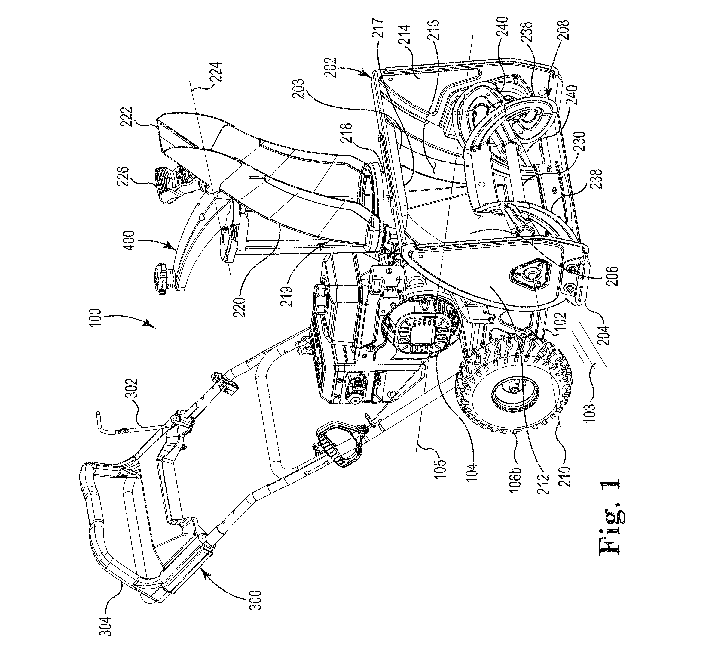
Embodiments described herein are directed to walk-behind snowthrowers and, more particularly, to a propulsion system for a single-stage snowthrower. Walk-behind snowthrowers typically fall into one of two categories. Two-stage snowthrowers include a horizontally-mounted, rigid helical auger that cuts snow and moves it at a low speed transversely toward a discharge area. Once the snow reaches the discharge area, a higher speed impeller collects and ejects the snow outwardly away from the snowthrower through a discharge chute. Wheels supporting two-stage snowthrowers are typically powered to propel the snowthrower over a ground surface during operation. Conversely, single stage snowthrowers typically achieve both snow collection and ejection using a horizontally mounted, single-stage high-speed rotor. The rotor may be shaped to move the snow transversely toward a discharge area. At or near the discharge area, the rotor may include paddles configured to directly eject the snow outwardly through a discharge chute. Typically, the rotor of a single-stage snowthrower is constructed of an elastomeric material. Thus, unlike the auger of a two-stage unit, the rotor may be configured to contact the ground surface during operation. Such contact may assist in propelling the single-stage snowthrower, negating the need for powered propulsion wheels. Passive wheels may still be provided to support the snowthrower in rolling engagement with the ground surface. In one embodiment, a snowthrower is provided that includes: a rotor housing defining a collection opening and a discharge outlet; a discharge chute attached to the housing and in fluid communication with the discharge outlet; and a first drive member located near a first side of the housing and a second drive member located near a second side of the housing. A rotor may also be provided. The rotor may be partially enclosed by, and adapted to rotate within, the housing. The rotor is adapted to both: collect snow that enters the housing through the collection opening; and eject the snow through the discharge outlet. A transmission may be provided that includes: an input shaft; and independent first and second output axles operatively connecting the input shaft to the first and second drive members, respectively. A prime mover may be operatively attached to the housing, wherein the prime mover is adapted to provide power to both the rotor and the transmission. In another embodiment, a snowthrower is provided that includes: a frame having lateral first and second sides; first and second drive members located on or near the first and second sides of the frame, respectively; a rotor housing attached to the frame, the rotor housing defining a partially enclosed volume having a collection opening and a discharge outlet; and a discharge chute operatively attached to the rotor housing and in fluid communication with the discharge outlet. A rotor may also be provided and connected to the rotor housing. The rotor is adapted to rotate about a first axis within the partially enclosed volume, wherein the rotor includes a first portion adapted to transport snow in a direction parallel to the first axis, and a second portion including a paddle offset from, and adapted to rotate about, the first axis. The paddle is adapted to eject the snow outwardly through the discharge chute. A transmission may be attached to the frame and includes: an input shaft; and independent first and second output axles attached to the first and second drive members, respectively. The transmission is adapted to synchronously drive the first and second output axles at a user-selectable, variable speed. A prime mover may be attached to the frame and adapted to provide power to both the rotor and the input shaft of the transmission. In yet another embodiment, a snowthrower is provided that includes: a frame having first and second sides; first and second drive wheels located on or near the first and second sides of the frame, respectively; a rotor housing attached to the frame, the rotor housing defining a partially enclosed volume having a collection opening and a discharge outlet; and a discharge chute operatively attached to the rotor housing and in fluid communication with the discharge outlet. A rotor may also be provided and connected to the rotor housing. The rotor is adapted to rotate within the partially enclosed volume about a first axis, wherein the rotor includes a first portion adapted to transport snow received through the collection opening, and a second portion also adapted to rotate about the first axis, the second portion adapted to eject the snow outwardly through the discharge chute. A transmission is attached to the frame and includes: an input shaft; and independent first and second output axles attached to the first and second drive wheels, respectively. The transmission is adapted to synchronously drive the first and second output axles, at a variable speed. A prime mover is attached to the frame and adapted to provide power to both the rotor and the input shaft of the transmission. The above summary is not intended to describe each embodiment or every implementation. Rather, a more complete understanding of various illustrative embodiments will become apparent and appreciated by reference to the following Detailed Description of Exemplary Embodiments in view of the accompanying figures of the drawing. Exemplary embodiments will be further described with reference to the figures of the drawing, wherein: The figures are rendered primarily for clarity and, as a result, are not necessarily drawn to scale. Moreover, various structure/components, including but not limited to fasteners, electrical components (wiring, cables, etc.), and the like, may be shown diagrammatically or removed from some or all of the views to better illustrate aspects of the depicted embodiments, or where inclusion of such structure/components is not necessary to an understanding of the various exemplary embodiments described. The lack of illustration/description of such structure/components in a particular figure is, however, not to be interpreted as limiting the various embodiments in any way. In the following detailed description of illustrative embodiments, reference is made to the accompanying figures of the drawing which form a part hereof. It is to be understood that other embodiments, which may not be described and/or illustrated herein, are certainly contemplated. All headings provided herein are for the convenience of the reader and should not be used to limit the meaning of any text that follows the heading, unless so specified. Moreover, unless otherwise indicated, all numbers expressing quantities, and all terms expressing direction/orientation (e.g., vertical, horizontal, perpendicular, parallel, etc.), in the specification and claims are understood as being modified by the term “about.” Due to their simplicity, single-stage snowthrowers are a cost-effective solution in many snow removal applications. However, they are sometimes perceived as unsuitable for deep or extremely icy snow conditions due to, for example, their flexible rotor, lack of a dedicated second-stage impeller, or their lack of powered drive wheels. Moreover, many single stage snowthrowers utilize a simplistic chute control mechanism that may not enjoy the same convenience and directional control as chute controls typically found on two-stage machines. Embodiments described and illustrated herein may address some of these issues. For instance, It is noted that the terms “comprises” and variations thereof do not have a limiting meaning where these terms appear in the accompanying description and claims. Further, “a,” “an,” “the,” “at least one,” and “one or more” are used interchangeably herein. Moreover, relative terms such as “left,” “right,” “front,” “fore,” “forward,” “rear,” “aft,” “rearward,” “top,” “bottom,” “side,” “upper,” “lower,” “above,” “below,” “horizontal,” “vertical,” and the like may be used herein and, if so, are from the perspective of one operating the snowthrower 100 while the snowthrower is in an operating configuration, e.g., while the snowthrower 100 is positioned such that wheels 106 and skids 204 rest upon a generally horizontal ground surface 103 as shown in Still further, the suffixes “a” and “b” may be used throughout this description to denote various left- and right-side parts/features, respectively. However, in most pertinent respects, the parts/features denoted with “a” and “b” suffixes are substantially identical to, or mirror images of, one another. It is understood that, unless otherwise noted, the description of an individual part/feature (e.g., part/feature identified with an “a” suffix) also applies to the opposing part/feature (e.g., part/feature identified with a “b” suffix). Similarly, the description of a part/feature identified with no suffix may apply, unless noted otherwise, to both the corresponding left and right part/feature. As illustrated in The snowthrower 100 may include a housing assembly 200 attached to the frame 102. Among other components, the housing assembly may include a snow-engaging rotor 208 and a rotor housing 202, the latter defining a partially enclosed volume such that the housing may at least partially surround or enclose the rotor. Lowermost portions of the housing 202 (e.g., the skids 204), together with the wheels 106, may form ground contact portions of the snowthrower 100. Stated alternatively, lowermost portions of both drive wheels 106 and the housing 202 may together define an operating plane upon which the snowthrower operates. The housing 202 may define a collection opening 206 positioned forward of the rotor 208. The rotor is configured, as described in more detail below, for rotating (e.g., via engine 104 power) within, and relative to, the housing 202 about a transverse or rotor axis 210. The housing 202 may include a pair of spaced-apart sidewalls 212, 214 connected to one another by a rear wall 216 such that the housing forms the generally front-facing collection opening 206 defining a partially enclosed volume or chamber containing the rotor 208. In some embodiments, the rear wall 216 may also form an upper wall of the housing while, in other embodiments, a discrete upper wall may be provided. Regardless of the wall configuration, the rotor may be positioned between the collection opening 206 and the rear wall 216 as shown in As used herein, “longitudinal axis” or “longitudinal direction” refers to a long axis of the snowthrower 100, e.g., the centerline longitudinal axis 105 extending in the travel or fore-and-aft direction as shown in The housing assembly 200 may further include a discharge opening or outlet 217 and a chute assembly 219. The chute assembly 219 may include a discharge passageway or chute 218 operatively attached to the housing 202 such that a lower end of the discharge chute fluidly communicates with the discharge outlet 217 formed in the housing 202 (in the rear wall 216 (or an upper wall) of the housing). Accordingly, the chute 218 may communicate with the partially enclosed volume of the housing 202 and, thus, with the open-face collection opening 206. In one embodiment, the chute assembly 219 also includes an upper or directional chute 220 operable to rotate, relative to the housing 202, about a chute axis 221 (see In the illustrated embodiment, power transmission to the rotor 208 is controlled by a movable idler pulley 126. That is, when the bail 302 is in the engaged position (see A second idler pulley 128 may be used to tension the drive belt 110. In the illustrated embodiment, the idler pulley 128 may be configured during manufacture such that it is always biased to an engaged position, i.e., the belt 110 may be configured to always transmit power to the jackshaft pulley 114 and to the pulley 118 when the engine 104 is running. In such an embodiment, the speed of the snowthrower 100 may be controlled by direct manipulation of the transmission 117 itself through a user input, e.g., through the speed control device 304 of As further shown in The handle 305 may further include upwardly extending (e.g., perpendicular to the slide portions 310) grip portions 314. The exact orientation of the grip portions 314 may be selected to provide the average sized operator with a comfortable grip during snowthrower operation. By providing a grip portion 314 with at least a partially upright configuration as shown, the operator may be well-positioned to impart steering/turning forces to the snowthrower as compared to grip portions that may be more horizontal in construction. By pushing the speed control device 304 forward along the side bars 312 of the handle assembly, an interconnection (e.g., cable 309 of In other respects, the handle 305 may operate in a manner similar to that described in U.S. Pat. No. 6,082,083 to Stalpes et al. The transmission 117 may include a variable speed drive system provided, in one embodiment, by a variable engagement or cone clutch as further described below. Thus, for a fixed (e.g., constant), no-load power level provided to the input shaft 116 (via the pulley 118), the transmission 117 may synchronously drive the output axles 130 As illustrated in The intermediate shaft 506 may include a pinion gear 510 that drivingly engages an axle gear 512. Stated another way, the axle gear 512 is in mechanical engagement with the second portion of the clutch 508 and is operatively located between the input shaft 116 and the first and second axles 130. Disposed between the axle gear 512 and each of the output axles 130 The flange portion 516 may further provide a ramped surface 524 between adjacent protrusions 518 as shown in Such a configuration allows one shaft 130 to spin faster than the axle gear 512 (and thus faster than the other shaft 130), thereby allowing the operator to force the snowthrower to turn (e.g., by manually imparting a turning force to the snowthrower). Moreover, when the snowthrower is pushed by the operator at a speed faster than the axle gear 512 is driving, both jaw clutches (514 In order to collect and remove snow during snowthrower 100 operation, the rotor 208 may rotate about the transverse rotor axis 210 (see As shown in As indicated elsewhere herein, the housing assembly 200 may also include the chute assembly 219, e.g., the discharge chute 218 and the directional chute 220. In the illustrated embodiment, the chute assembly 219 may also include various components such as adapter 229 that permit attachment of the directional chute 220 to the discharge chute 218 in a manner that permits the former to rotate relative to the latter. As best viewed in In the illustrated embodiment, the discharge portion 236 is located toward the center of the rotor/housing 202. As a result, collecting portions 234 are provided on each outboard side of the discharge portion 236. However, embodiments wherein only one collecting portion, and/or more than one discharge portion, are contemplated. In general, the collecting portions 234 of the rotor 208 are adapted to work in conjunction with the corresponding portions of the snowthrower (e.g., semi-cylindrical lower portion 233 and upper curved portion 237) of the housing 202, while the discharge portion 236 is adapted to work in conjunction with the discharge portion of the housing (e.g., the transition zone 235) as further described below. Each collecting portion 234 of the rotor may include one or more flytes 238 as shown in Once again, the flytes 238 are adapted, when rotating, to collect snow entering the housing 202 through the collection opening 206 and transport it (in a direction parallel to the rotor axis 210) toward the discharge portion 236 of the rotor 208 (e.g., toward the transition zone 235 of the housing). To accomplish this, each flyte 238 may form a partial helix as perhaps best shown in Unlike conventional single stage snowthrowers, the snowthrower 100 does not rely upon rotor 208/ground contact for propulsion. Rather, the drive wheels 106, as described above, may propel the snowthrower during operation. Accordingly, the rotor 208 may be spaced-apart from the ground surface 103 such that a surface of revolution 242 defined by an outermost edge of the rotor (as it rotates about the axis 210) is offset from the operating plane formed by the ground surface 103 as shown in Each of the collecting portions 234 of the rotor 208 may terminate at the discharge portion 236 (see Each paddle 244 may further form a concave ejection surface 246 as illustrated in In one embodiment, the helical flytes 238 are made from the first material (e.g., metal) having a first thickness, while the snow ejection surface 246 is made of a second material of greater compliance (e.g., elastomer such as rubber) having a second thickness that is, in one embodiment, two or more times greater than the first thickness (i.e., the flytes may have a thickness that is 50% or less than a thickness of the paddles 244). As a result, the flytes 238 may potentially be better suited to cut through icy snow than the elastomeric, thicker flytes of a typical single-stage rotor. A portion of the rear wall 216 of the housing 202 may, as described above, form the transition zone 235 that assists with receiving and transitioning snow (delivered by the flytes 238) for vertical ejection by the ejection surface 246 of the rotor 208. In the illustrated embodiment, the transition zone 235 may take the shape of an inverted funnel when viewed from the front as shown in The result of the exemplary construction of the rotor 208 and the transition zone 235 shown herein is that, at least during normal (stead-state) operation, snow is brought to the transition zone 235 by the flytes 238 (or collected directly by the paddles 244) and is then ejected upwardly along the surface 239 such that the ejected snow converges as it moves toward the outlet 217. Stated alternatively, the shape of the snow ejecting surface 246, along with the shape of the rear surface 239 and the transition walls 241, may direct or focus ejected snow so that it more effectively enters the discharge chute 218 as compared to a chute having a round cross-sectional shape. As further shown in It is believed that the negative rake angle of the paddles 244/ejection surfaces 246 provides various benefits. For instance, the negative rake angle may assist it discharging the snow in a direction that is away from the paddle (e.g., outwardly from the surface of revolution 242 formed by the rotor). As a result, snow may be ejected upwardly through the outlet 217 and into the discharge chute 218 as opposed to potentially being carried around to the front of the rotor 208 and ejected forwardly through the collection opening 206 of the housing 202. Other features of the exemplary snowthrower 100 may also contribute to effective snow ejection through the discharge chute 218. For example, as shown in In conventional single-stage snowthrowers, an ejection baffle is often provided along an inside upper portion of the housing to block excessive forward ejection of snow. However, it has been found that embodiments of the snowthrower 100 may reduce the occurrence of forwardly ejected snow to a point wherein a substantially smaller ejection baffle (see, e.g., the optional baffle 203 in The exemplary housing assemblies 200 described herein provide other advantages. For example, It is believed that such a polygonal shape (provided by the rear surface 239, the transition walls 241, and the other inner walls 243) may assist with ejection efficiency (e.g., assist with directing ejected snow through the outlet) as compared to the more commonly-found circular shape. For example, these walls/surfaces appear to interfere with the tendency for ejected snow to helix or “cork-screw” as it travels upwardly from the rotor 208 toward the chute 218. Such a phenomena is known to occur in some round chute, single-stage snowthrowers, especially when snow is collected across less than all of the housing width. The exemplary chute rotation control mechanism 400 will now be described with reference to With reference first to In an alternate embodiment, the knob 410 may be optional, i.e., the receiver 411 may be configured as a rotating or non-rotating, smooth-surface handle (formed along the axis 412) that is suitable for grasping by the operator's hand directly. Accordingly, in either knobbed or knobless configurations, a handle may be provided that permits the operator to impart a rotational force to the lever 404, through the lever's entire range of motion, without requiring the operator to adjust or otherwise reposition his or her grip. The support member 402 may hold a platform 414 operable to support the lever 404 and the associated mechanism structure. In the illustrated embodiment, the mechanism 400 includes an indexing member 418 which may be attached to the platform 414, e.g., with a shoulder bolt 407, the shoulder bolt 407 being threadably engagable with the platform as shown in The indexing member 418 may further include a toothed perimeter 425 as shown in To assemble the mechanism 400, the indexing member 418 may be attached to the platform 414 with the shoulder bolt 407, after which the pawl 427 may be attached to the platform using the shoulder bolt 429. The bracket 432 may then be engaged with (e.g., slide over) the support member 402. A first end of the spring 430 may then attach to an aperture 426 in the pawl 427, while a second end attaches to the bracket 432. Subsequently, the fastener 434 may be passed through the cover 435 and the fastener hole in the bracket and threaded into the platform 414. To attach the indexing member 418 to the directional chute 220, fasteners (not shown) may pass with clearance through lugs 421 formed on the indexing member and threadably engage threaded holes 409 located on the directional chute. The lever 404 may then be placed over the indexing member 418 such that a recess 423 formed on the lower side of the lever 404 receives the shoulder bolt 407 with little or no radial clearance as shown in The optional knob 410 may then be attached to the second end 408 of the lever 404 with the fastener 415. A cap 422 may be placed over the knob to cover the fastener head 415. When the operator wishes to rotate the directional chute 220 (e.g., relative to the discharge chute and about the chute axis 221), the knob 410 (or receiver 411) may be grasped (e.g., by hand) and a rotational force imparted to the lever 404 to rotate the chute 220 about an axis of the shoulder bolt 407 (which axis is coincident with the chute axis 221). As the knob 410 is rotationally coupled to the lever 404, the lever may be moved through its entire range of motion (e.g., about 200 degrees) without requiring the operator to reposition his or her hand relative to the knob. That is, the lever may be operated in a manner similar to that of a manual automotive window crank. In order to hold the directional chute 220/lever 404 in the desired location once the knob 410 is released, the indexing member 418/pawl 427 may act as a retention device. For example, the spring 430 may cause the finger 428 of the pawl 427 into biased engagement between adjacent teeth of the toothed perimeter 425 of the indexing member. As a result, once the indexing member 418 is rotationally positioned such that the finger 428 is biased into a valley between two teeth of the perimeter 425, the directional chute is held in place. To further rotate the directional chute 220, the operator applies a threshold torque to the lever (via the knob 410 and about the lever pivot axis) sufficient to cause the finger 428 to cam out of the valley of the toothed perimeter 425, at which point the indexing member, and thus the lever and directional chute, may rotate. Continued application of force to the knob 410 permits the lever 404 to continue pivoting until reaching its desired position. Once the chute 220 is at the desired rotational position, the force applied to the knob 410 may be withdrawn by the operator, causing the finger 428 of the pawl 427 to again engage a valley between the two most proximate teeth on the toothed perimeter 425. The biasing force applied by the spring 430 is then sufficient to hold the indexing member 418 and the chute 220, in the set position until a threshold torque is again applied to the lever about the lever pivot axis. As a result of this construction, the operator may easily reposition the directional chute 220 by simply grasping the knob 410 (or the receiver 411) and rotating the lever 404 about the chute axis 221. The deflector 222 may also be pivoted (e.g., about the axis 224 (see While exemplary embodiments of the chute rotation control mechanism are described in detail above, it is to be understood that these embodiments are illustrative only and a variety of mechanisms may achieve the desired movement. For example, while shown as using a tension spring 430 to provide the biasing force to the pawl 427, other embodiments may use most any biasing mechanism, e.g., a torsion spring, an elastomeric element, etc. to achieve the desired effect. Moreover, while shown as a pawl 427 and gear tooth mechanism, most any device that provides sufficient friction to restrict unintentional rotation of the directional chute 220 may be utilized. Still further, in some embodiments, the chute rotation control mechanism may be replaced with, or include aspects of, other control mechanisms, see, e.g., U.S. Pat. No. 7,032,333 to Friberg et al. The complete disclosure of the patents, patent documents, and publications cited herein are incorporated by reference in their entirety as if each were individually incorporated. Illustrative embodiments are described and reference has been made to possible variations of the same. These and other variations, combinations, and modifications will be apparent to those skilled in the art, and it should be understood that the claims are not limited to the illustrative embodiments set forth herein. A self-propelled, single-stage snowthrower wherein, in one embodiment, drive members on each side of the snowthrower provide variable speed propulsion. A transmission that delivers power to the drive members may be adapted to de-clutch one of the two drive wheels when the ground speed of that wheel exceeds the driving speed of the transmission. In other embodiments, the snowthrower includes a rotor having a snow ejection surface forming a negative rake angle. Yet other embodiments include a chute rotation control mechanism that permits manual discharge chute rotation via one-handed input. 1. A snowthrower comprising:
a rotor housing defining a collection opening and a discharge outlet; a discharge chute attached to the housing and in fluid communication with the discharge outlet; a first drive member located near a first side of the housing and a second drive member located near a second side of the housing; a rotor partially enclosed by, and adapted to rotate within, the housing, the rotor adapted to both: collect snow that enters the housing through the collection opening; and eject the snow through the discharge outlet; a transmission comprising: an input shaft; and independent first and second output axles operatively connecting the input shaft to the first and second drive members, respectively; and a prime mover operatively attached to the housing and adapted to provide power to both the rotor and the transmission. 2. The snowthrower of 3. The snowthrower of 4. The snowthrower of 5. The snowthrower of 6. The snowthrower of 7. The snowthrower of 8. A snowthrower comprising:
a frame comprising lateral first and second sides; first and second drive members located on or near the first and second sides of the frame, respectively; a rotor housing attached to the frame, the rotor housing defining a partially enclosed volume having a collection opening and a discharge outlet; a discharge chute operatively attached to the rotor housing and in fluid communication with the discharge outlet; a rotor connected to the rotor housing and adapted to rotate about a first axis within the partially enclosed volume, wherein the rotor comprises a first portion adapted to transport snow in a direction parallel to the first axis, and a second portion comprising a paddle offset from, and adapted to rotate about, the first axis, the paddle adapted to eject the snow outwardly through the discharge chute; a transmission attached to the frame, the transmission comprising: an input shaft; and independent first and second output axles attached to the first and second drive members, respectively, wherein the transmission is adapted to synchronously drive the first and second output axles at a user-selectable, variable speed; and a prime mover attached to the frame and adapted to provide power to both the rotor and the input shaft of the transmission. 9. The snowthrower of 10. The snowthrower of 11. The snowthrower of 12. The snowthrower of 13. The snowthrower of 14. The snowthrower of 15. The snowthrower of 16. The snowthrower of 17. The snowthrower of a variable engagement clutch having a first portion in mechanical engagement with the input shaft; an axle gear in mechanical engagement with a second portion of the variable engagement clutch; and first and second jaw clutches disposed between the axle gear and the first and second output axles, respectively. 18. The snowthrower of 19. The snowthrower of 20. A snowthrower comprising:
a frame comprising first and second sides; first and second drive wheels located on or near the first and second sides of the frame, respectively; a rotor housing attached to the frame, the rotor housing defining a partially enclosed volume having a collection opening and a discharge outlet; a discharge chute operatively attached to the rotor housing and in fluid communication with the discharge outlet; a rotor connected to the rotor housing and adapted to rotate within the partially enclosed volume about a first axis, wherein the rotor comprises a first portion adapted to transport snow received through the collection opening, and a second portion also adapted to rotate about the first axis, the second portion adapted to eject the snow outwardly through the discharge chute; a transmission attached to the frame, the transmission comprising: an input shaft; and independent first and second output axles attached to the first and second drive wheels, respectively, wherein the transmission is adapted to synchronously drive the first and second output axles, at a variable speed; and a prime mover attached to the frame and adapted to provide power to both the rotor and the input shaft of the transmission.BACKGROUND
SUMMARY
BRIEF DESCRIPTION OF THE VIEWS OF THE DRAWING
DETAILED DESCRIPTION OF EXEMPLARY EMBODIMENTS
Rotor Drive and Wheel Propulsion System
Housing Assembly
Chute Rotation Control Mechanism