DEVICE FOR REMOVING COVERINGS LAID ON PLANAR SURFACES
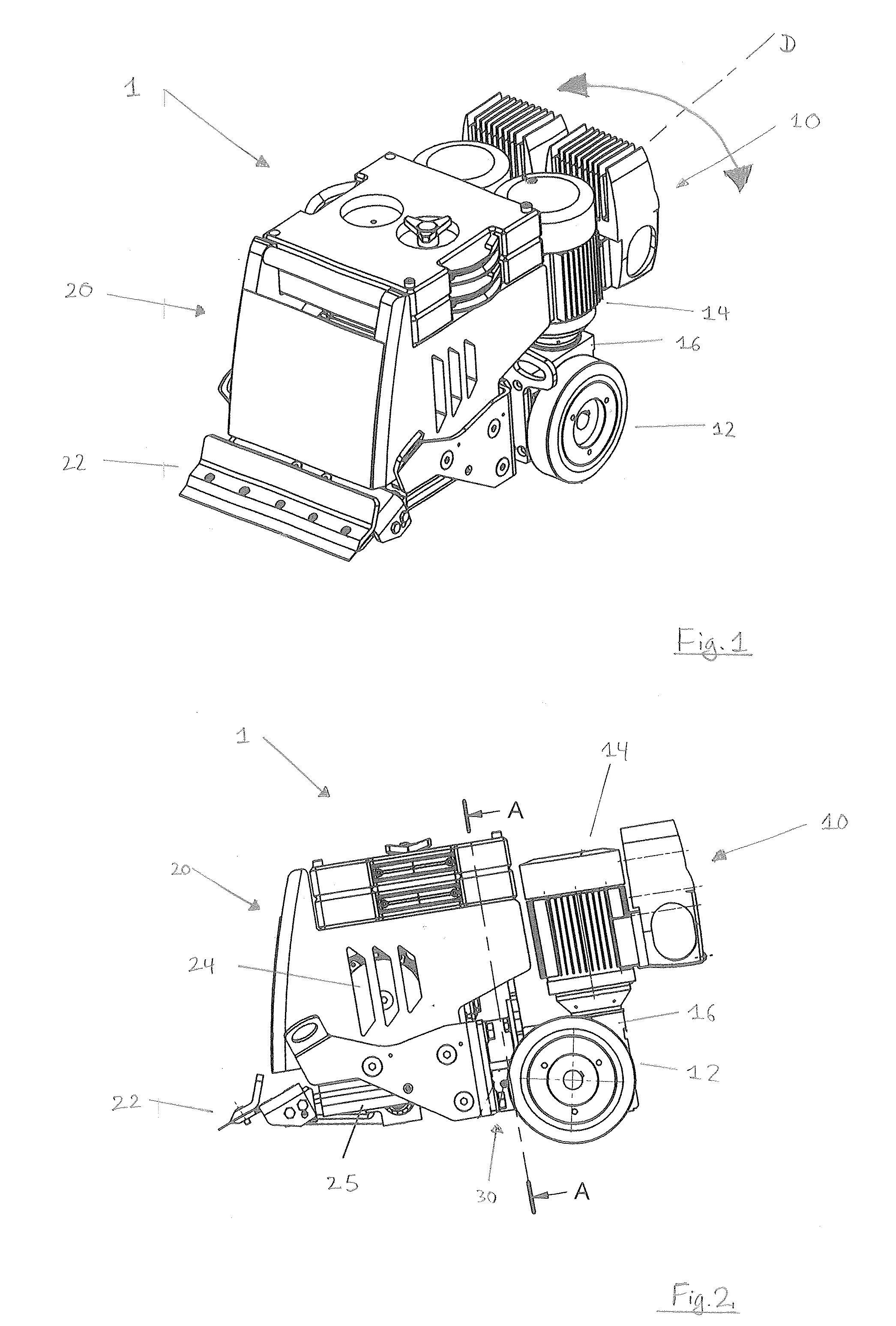
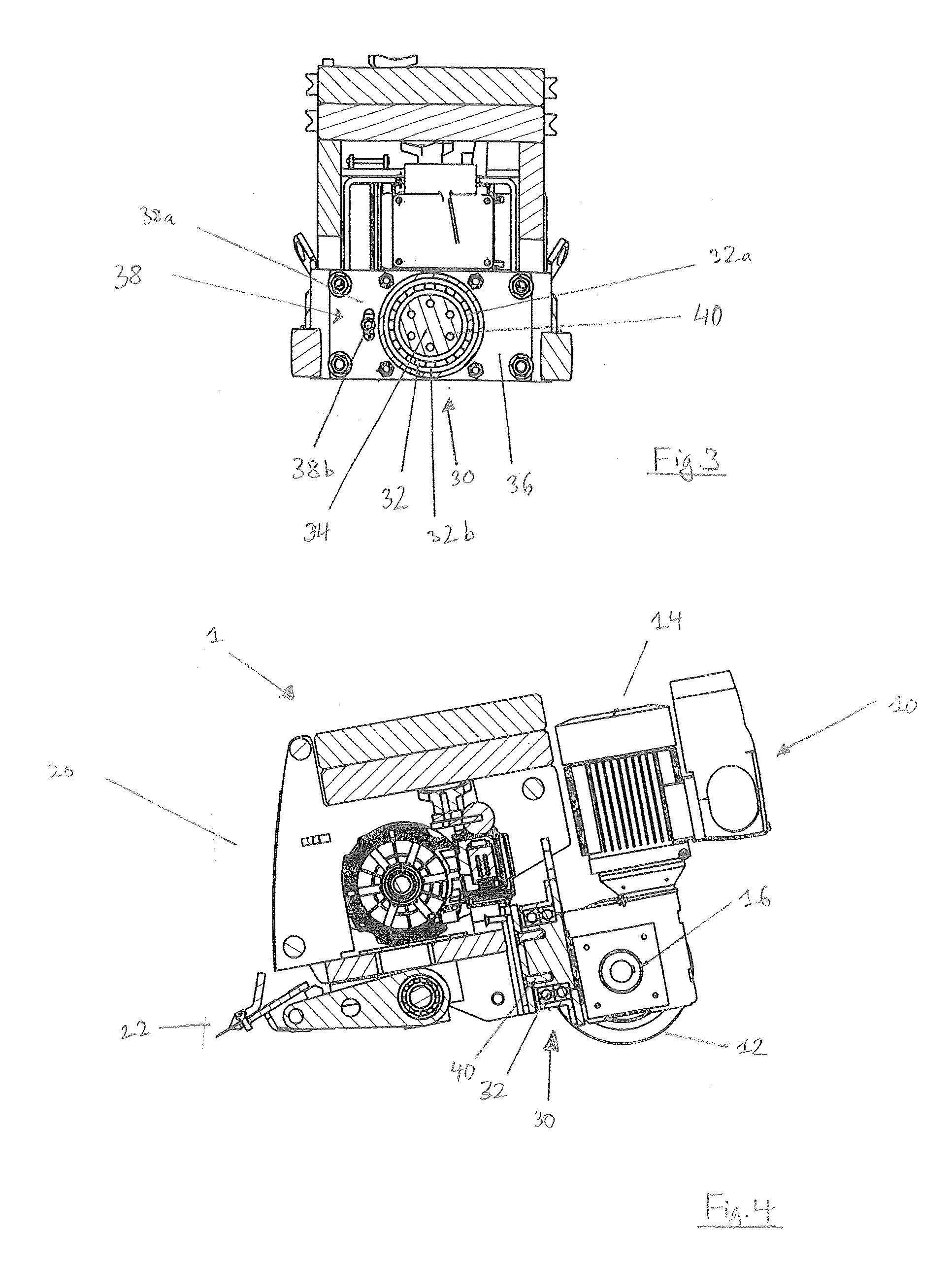
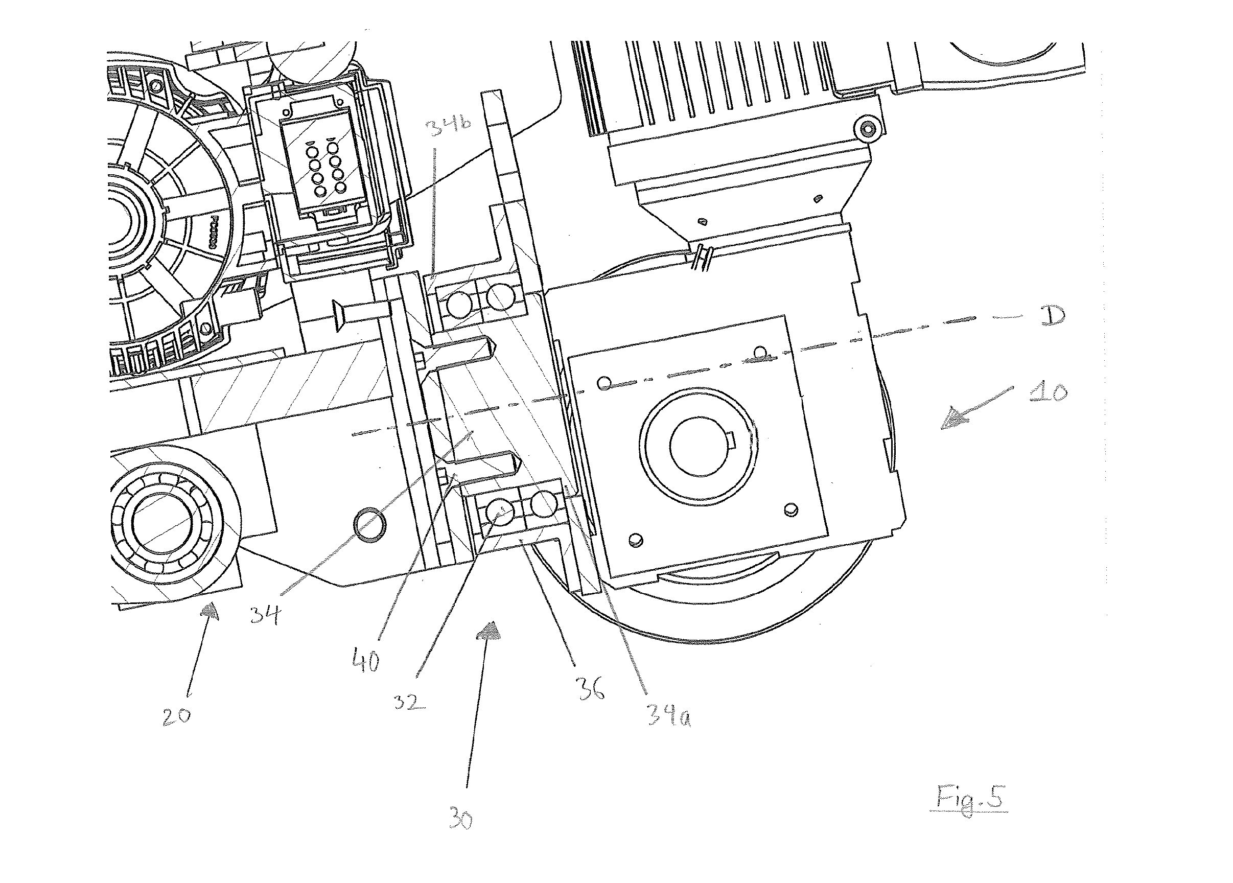
The present invention relates to a device for removing coverings laid on planar surfaces, comprising a drive unit having a pair of drive wheels, a first drive motor and a transmission for driving the drive wheels, and comprising a motor-driven striking mechanism having a cutting blade and a second drive motor, the cutting blade being connected to the second drive motor by a connecting rod. Coverings laid on planar surfaces, such as carpets laid on floors, are adhered to their supporting surface in the laid state. The coverings are thereby prevented from slipping and sliding about when being walked on. If such coverings are to be replaced by new coverings as a result of wear and tear or damage, the old coverings must be removed first. Devices are already known which enable such particular coverings to be removed in pieces or in strips. In this case, a motor-driven, vibrating cutting blade is pushed between the covering and the planar supporting surface. When there are bumps, the cutting blade may not rest on the entire surface of the floor, particularly if parts of the covering get under a drive wheel of the device. One idea of the present invention to provide an improved device for removing coverings laid on planar surfaces which enables the cutting blade to rest on the entire surface of the floor even when the device travels over bumps. A device for removing coverings laid on planar surfaces comprises a drive unit having a pair of drive wheels and a first drive motor for driving the drive wheels, and comprising a motor-driven striking mechanism having a cutting blade and a second drive motor, the cutting blade being connected to the second drive motor by a connecting rod, wherein the drive unit and the striking mechanism have an articulated connection which is designed in such a way that the drive unit and the striking tool are mounted so as to be rotatable relative to one another. It can thereby be ensured that when the device travels over bumps the drive unit and the striking mechanism are rotatable relative to one another. It may be provided in some embodiments that the drive unit and the striking mechanism are mounted so as to be rotatable relative to one another about an axis of rotation of the articulated connection which is in parallel with a longitudinal axis of the device. By means of the rotatability of the drive unit and the striking mechanism relative to one another about the axis of rotation of the articulated connection, which is in parallel with the longitudinal axis of the device, the drive unit is rotated about the axis of rotation of the articulated connection, i.e. radially with respect to the longitudinal axis of the device, relative to the striking mechanism when for example one of the drive wheels travels over a bump. Therefore the bump can be travelled over without the rotational movement of the drive unit being transmitted to the striking mechanism. The cutting blade of the striking mechanism therefore rests on the entire surface of the floor even when the device travels over a bump. It may further be provided in some embodiments that the articulated connection has a rolling bearing and a first joint and a second joint, the first joint being connected to the striking mechanism and to an inner ring of the rolling bearing for conjoint rotation and the second joint being connected to the drive unit and to an outer ring of the rolling bearing for conjoint rotation. A rotational movement of the drive unit relative to the striking mechanism thus causes the outer ring of the rolling bearing to rotate relative to the inner ring of the rolling bearing. According to some embodiments, it is provided that the articulated connection has an axial locking mechanism of the first and second joint, an end portion of the first joint having a larger circumference than an inner wall of the inner ring and an end portion of the second joint having a smaller circumference than an outer wall of the outer ring. The first joint and the second joint are therefore locked in the longitudinal direction. Furthermore, the articulated connection consisting of the rolling bearing and the first and second joint forms a connection between the drive unit and the striking mechanism. According to some embodiments, it is provided that the articulated connection has a limiting element which limits a rotation of the drive unit and the striking mechanism relative to one another. Providing the limiting element furthermore ensures that the drive unit and/or the striking mechanism are prevented from tilting sideways in the event of a misalignment. It may further be provided in some embodiments that the limiting element is designed in the form of a slot which is arranged so as to be adjacent to the articulated connection in a housing wall of the device, the slot being designed so as to be concentric with the articulated connection and a bolt engaging in the slot, which bolt is connected to the drive unit and/or the striking mechanism. The rotation of the drive unit and the striking mechanism relative to one another can thereby be effectively limited. According to some embodiments, it is provided that the drive unit and the striking mechanism are rotatable relative to one another at an angle of up to 20°, preferably at an angle of up to 15°, particularly preferably at an angle of up to 10°. It can thereby be ensured that when the device travels over smaller to larger bumps the cutting blade of the striking mechanism rests on the entire surface of the floor. According to some embodiments, it is provided that the first joint is connected to the striking mechanism by a plurality of fastening means, preferably flat headed screws, which screw a housing wall of the striking mechanism to the first joint. Therefore, the striking mechanism can be connected to the first joint in a secure and stable manner. It may further be provided in some embodiments that the second joint is formed by a housing wall of the drive unit. Therefore, advantageously, additional fastening means for fastening the second joint to the drive unit do not need to be provided. According to some embodiments, it is provided that the rolling bearing is formed by a double-row deep groove ball bearing. By providing a double-row deep groove ball bearing, good stability of the bearing can be ensured, particularly with respect to absorbing radial forces. Embodiments of the invention are explained in more detail in the following description and illustrated in the figures of the drawings, in which: Like reference numerals denote like or functionally like components, unless otherwise stated. The striking mechanism 20 has a cutting blade 22, a second drive motor 24 and a connecting rod 25. The cutting blade 22 is connected to the second drive motor 24 by the connecting rod. The second drive motor 24 sets the cutting blade 22 into an impulsive vibrating motion by means of the connecting rod 25 in order to lift the covering. As can be seen in the embodiment shown in When the device 1 travels over a bump, which can for example occur by means of residues of the covering getting under a drive wheel 12, the drive unit 10 is mounted so as to be rotatable relative to the striking mechanism 20 by providing the articulated connection 30, which connects the drive unit 10 to the striking mechanism 20, as a result of which the drive unit 10 is rotated about an axis of rotation D of the articulated connection 30 which is in parallel with a longitudinal axis of the device 1 and the cutting blade 22 of the striking mechanism 20 rests on the entire surface of the floor. The limiting element 38 is shown in The first joint 34 is further connected to the striking mechanism 20 by a plurality of fastening means 40. According to the present embodiment, the fastening means 40 are formed by flat headed screws. By means of the flat headed screws, the striking mechanism 20, in particular a housing wall of the striking mechanism 20, is screwed to the first joint 34. An axial locking mechanism of the first and second joint 34, 36 is furthermore provided. In this case, an end portion 34 The invention is not restricted to the above-mentioned embodiments. Within the scope of protection, the device 1 according to the invention for removing coverings laid on planar surfaces can also, however, assume a configuration other than the configurations specifically described above. A device for removing coverings laid on planar surfaces includes a drive unit having a pair of drive wheels and a first drive motor for driving the drive wheels, a motor-driven striking mechanism having a cutting blade and a second drive motor. The cutting blade connects to the second drive motor by a connecting rod. The drive unit and the striking mechanism have an articulated connection which is designed in such a way that the drive unit and the striking mechanism are mounted so as to be rotatable relative to one another. 1.-11. (canceled) 1. A device for removing coverings laid on planar surfaces, comprising:
a drive unit having a pair of drive wheels; a first drive motor for driving the drive wheels; a motor-driven striking mechanism having a cutting blade; and a second drive motor, the cutting blade being connected to the second drive motor by a connecting rod, wherein the drive unit and the striking mechanism have an articulated connection which is designed in such a way that the drive unit and the striking mechanism are mounted so as to be rotatable relative to one another. 2. The device of 3. The device of 4. The device of 5. The device of 6. The device of 7. The device of 8. The device of 9. The device of 10. The device of 11. The device of 12. The device of FIELD OF THE INVENTION
BACKGROUND OF THE INVENTION
SUMMARY OF THE INVENTION
BRIEF DESCRIPTION OF THE DRAWINGS
DETAILED DESCRIPTION OF EMBODIMENTS OF THE INVENTION