SMART EJECTION TRAYS FOR USE WITH MEDICATION CONTAINERS
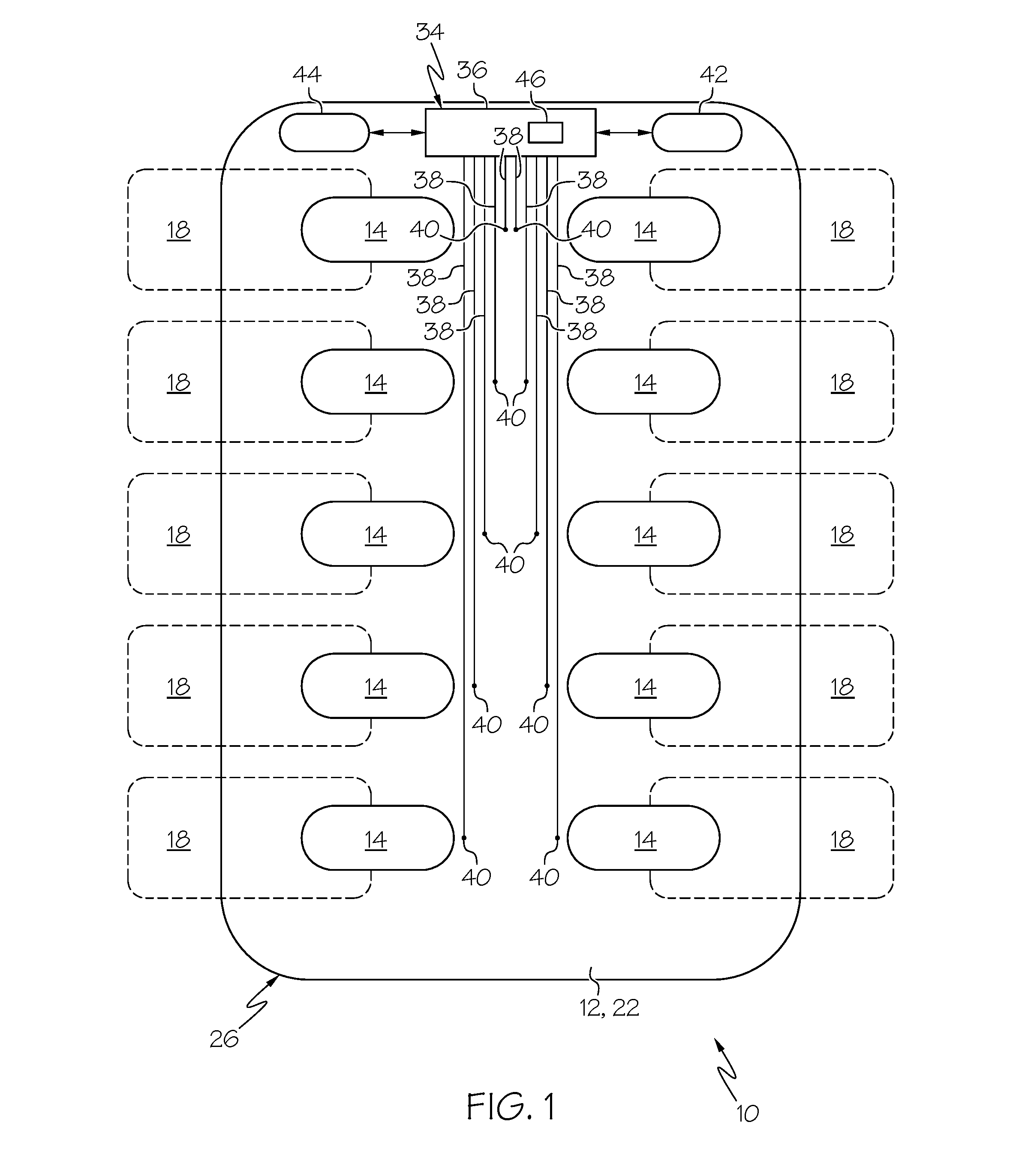
Field of the Disclosure The present subject matter relates to monitoring the medication intake of a subject. More particularly, the present subject matter relates to smart ejection trays for use in combination with medication containers for monitoring the medication intake of a subject. Description of Related Art Frequently, a doctor or medical care provider will issue instructions to a subject to periodically ingest one or more doses of medication in the form of a pill or tablet or capsule or the like as part of a treatment regimen. Unless the subject is within a facility under the control of the doctor or medical care provider (e.g., a hospital or nursing home), it can be difficult for the doctor or medical care provider to know whether the subject is ingesting the prescribed medication at the proper times. Accordingly, it would be advantageous to provide systems and methods that increase the likelihood that a subject will properly follow a prescribed medication routine. There are several aspects of the present subject matter that may be embodied separately or together in the devices and systems described and claimed below. These aspects may be employed alone or in combination with other aspects of the subject matter described herein, and the description of these aspects together is not intended to preclude the use of these aspects separately or the claiming of such aspects separately or in different combinations as may be set forth in the claims appended hereto. In one aspect, an ejection tray is provided for use in combination with a medication container including a medication-containing cell. The tray includes a frame configured to receive at least a portion of the medication container. An actuator is movably associated with the frame to eject the medication from the cell. A switch is associated with the frame and configured to change from a first state to a second state upon the actuator being moved to eject the medication from the cell. A host processor is associated with the frame and is electrically coupled or selectively coupled to the switch. The host processor is programmed to detect a change in the state of the switch. As required, detailed embodiments of the present invention are disclosed herein; however, it is to be understood that the disclosed embodiments are merely exemplary of the invention, which may be embodied in various forms. Therefore, specific details disclosed herein are not to be interpreted as limiting, but merely as a basis for the claims and as a representative basis for teaching one skilled in the art to variously employ the present invention in virtually any appropriate manner. According to an aspect of the present disclosure, a smart ejection tray 10 may be used in combination with a medication container 12 ( The medication container 12 includes at least one cell 14 in which a dose of medication 16 is contained ( Each cell 14 may be formed of any suitable material but, in one embodiment, each cell is formed of a thin plastic material or another deformable material. In particular, it may be advantageous for the cells 14 to be formed of a material that is generally rigid, but sufficiently deformable that an actuator or ejector wedge 18 of the tray 10, when brought into contact with the cell 14 (as will be described in greater detail), deforms the cell 14. In a preferred embodiment, the body of the medical container 12 takes the general form of a blister pack, with a thin plastic sheet 20 ( Each cell 14 is preferably closed or overlaid by a cover 22 through which medication 16 within the cell 14 may be accessed. In one embodiment, the cover 22 is a thin sheet of material, such as a metallic foil or an at least partially light-transmissive (e.g., transparent or translucent) sheet, which may be broken to allow medication 16 to pass out of the cell 14. In such an embodiment, a base 24 of the cell 14 may be pressed toward the frangible cover 22 by a user operating an associated actuator 18 of the tray 10 (as will be described in greater detail) until the force on the cover 22 exceeds the strength of the cover 22, at which point the cover 22 breaks and the medication 16 may be removed or is ejected from the cell 14. If the medication container 12 is provided with a plurality of cells 14, it may be preferred for a single cover 22 to overlay all of the cells 14, but it is also within the scope of the present disclosure for two or more cells of the same medication container to be provided with separate covers. For example, in one embodiment, different cells are each overlaid by separate, non-frangible (e.g., hinged) covers. In the embodiment of It should be understood that the illustrated embodiment is merely exemplary and that the frame 26 may be differently configured without departing from the scope of the present disclosure. For example, the medication container 12 can take the form of a standard blister pack or other previously available and/or existing container or containers having some or all of the basic features described in one of a variety of available configurations, sizes, thicknesses of various walls and/or materials of construction. Also, the tray 10 can be sized, configured and made of materials such that the tray 10 clips onto or around the medication container 12, whether of a standard type or of a type specially designed for use in combination with the tray 10. Further, the frame 26 can achieve or contribute to such clip onto or around functions. The clipping function typically has the ability to securely capture the medication container 12, whether by siding action, snapping action, or a combination thereof. A circuit 34 is incorporated into or otherwise associated with the frame 26 of the ejection tray 10 ( In the embodiment of Most preferably, the number of cells 14 and switches 40 is the same, with each switch 40 associated with a different one of the cells 14. Each switch 40 is preferably paired with a different actuator 18 of the ejection tray 10, thereby providing a switch-actuator-cell combination. Each actuator 18 is movably associated with the frame 26 of the tray 10, such that the actuator 18 may be moved with respect to the frame 26. The way in which an actuator 18 is movably associated with the frame 26 may vary without departing from the scope of the present disclosure, provided that the actuator 18 may be moved in a way so as to allow the medication 16 of an associated cell 14 to be removed from the cell 14 or so as to cause the medication 16 to be ejected from that cell 14. In the illustrated embodiment, each actuator 18 extends through a different one of a plurality of openings or passages defined in the sidewalls 32 of the frame 26, with an inside or internal portion 48 of the actuator 18 positioned within the bounds of the frame 26 (e.g., within the open interior of the frame 26) and with an outside or external portion 50 of the actuator 18 positioned outside of the bounds of the frame 26. The internal portion 48 of the actuator 18 may be initially spaced or separated from the associated cell 14 or, if initially in contact with the associated cell 14, in contact with the cell 14 without deforming the cell 14. In the embodiment of The illustrated angled surface 52 has one portion (illustrated as a bottom or lower portion) positioned closer to the associated switch 40 or to the center of the tray 10 and another portion (illustrated as a top or upper portion) positioned farther from the associated switch 40 or center of the tray 10. The opening or passage in the sidewall 32 through which the actuator 18 extends is configured to allow the actuator 18 to be moved toward and away from the associated cell 14 to progressively cause a greater portion of the angled surface 52 to come into contact with the cell 14. By the illustrated configuration, moving the actuator 18 toward the associated cell 14 causes the angled surface 52 to contact and deform the cell 14, advancing the medication 16 contained within the cell 14 toward the cover 22 until the medication 16 is ultimately pressed through the cover 22. The illustrated actuators 18 are configured to move (e.g., by sliding) in a common, substantially horizontal plane (in the orientation of Moving an actuator 18 to the extent that the medication 16 of the associated cell 14 may be removed from or is ejected from the cell 14 also causes the associated switch 40 to change from the first state to the second state. In the first state, the switch 40 indicates that the medication 16 in the associated cell 14 has not yet been accessed. In the second state, the switch 40 indicates that the medication 16 in the associated cell 14 has been accessed. The way in which the switch 40 changes from the first state to the second state may vary without departing from the scope of the present disclosure. In one embodiment in which the switch 40 is permanently coupled to the host processor 36, the switch 40 is configured to transmit different signals or to have different electrical properties detected by the host processor 36 in the first and second states. In such an embodiment, the actuator 18 may cause a change in the state of the switch 40 either by physically contacting the switch 40 or without physically contacting the switch 40. In an alternative embodiment in which the switch 40 is selectively coupled to the host processor 36, the switch 40 may initially be out of communication with the host processor 36 in the first state (e.g., out of contact with the associated conductor 38) and then moved into communication with the host processor 36 by the actuator 18 to change the switch 40 to the second state (e.g., by the actuator 18 physically contacting and moving the switch 40 into contact with the associated conductor 38). In yet another embodiment in which the switch 40 is selectively coupled to the host processor 36, there may be a gap in the conductor 38 between the switch 40 and the host processor 36, with the actuator 18 having a conductive portion (or moving a conductive element) that bridges the gap to place the switch 40 in the second state, in which it may communicate with the host processor 36. Other relationships between an actuator 18 and associated switch 40 for changing the switch 40 from a first state to a second state (and, optionally, back to the first state from the second state) may also be employed without departing from the scope of the present disclosure. Thus, in use, a subject or user presses or otherwise advances the external portion 50 of the actuator 18 toward the associated cell 14 to eject the medication 16 in the cell 14 from the cell 14. So ejecting the medication 16 changes the switch 40 associated with the cell 14 to change from the first state (signifying that the medication 16 has not yet been accessed) to the second state (signifying that the medication 16 has been accessed). The actuators 18 may be differently colored from the tray 10 (e.g., with at least a portion of the tray 10 being a first color and at least a portion of the actuators 18 being a second color that is brighter than the first color) to call attention to themselves. The actuators 18 may also (or alternatively) include indicia (e.g., an arrow) to suggest the way in which the actuator 18 is to be manipulated to eject the medication 16. It may be advantageous for the portion of the actuator 18 to be manipulated (i.e., the external portion 50 in the illustrated embodiment) to be larger than the associated cell 14 to make it easier for a subject with impaired dexterity and/or eyesight to access the medication 16 contained within the cell 14. The host processor 36 detects that the switch 40 has changed from the first state to the second state and may take any of a number of actions in response. For example, the host processor 36 may include an internal, real-time clock 46 and record the time at which the state of the switch 40 changed (i.e., the time at which the medication 16 was accessed and ingested). This may be useful in allowing a medical professional to determine whether the subject is abiding by a prescribed medication routine. If the medication container 12 includes a plurality of cells 14, with the tray 10 including a plurality of switches 40, then the host processor 36 may be programmed to record the identity of the switch 40 that has changed its state, along with the sequence in which the states of the various switches 40 have changed. This may be especially advantageous if the different cells 40 contain different types and/or doses of medication 16, because a medical professional may use such information to determine whether the subject is ingesting the proper medication, in the proper order, and at the proper time. If provided, a communication device 44 electrically coupled to the host processor 36 may transmit data from the host processor 36 to a separate electronic device, such as a central database, computer, tablet, or cellular telephone. If a communication device 44 is provided, then the separate electronic device with which it communicates may include an internal clock, thereby allowing for the host processor 36 to omit an internal real-time clock. In such an embodiment, the host processor 36 may be programmed to cooperate with the communication device 44 to immediately transmit data to a separate electronic device upon a switch 40 changing to the second state. The separate electronic device may record the time at which it receives a signal from the communication device 44, thereby allowing the time at which a dose of medication 16 was accessed to be determined without relying upon an internal clock of the host processor 36. In such an embodiment, the host processor 36 may be configured to operate in a relatively low power state and be programmed to transition from the relatively low power state to a higher power state upon determining that a switch 40 has changed to its second state, with the host processor 36 in the higher power state cooperating with the communication device 44 to transmit one or more signals to a separate electronic device. In an alternative embodiment, rather than the host processor 36 and communication device 44 pushing signals to a separate electronic device, the host processor 36 may be programmed to record and retain data until the communication device 44 receives a signal or command from a separate electronic device to request data from the host processor 36. The host processor 36 may be configured to operate in the aforementioned relatively low power state before the communication device 44 receives a signal from a separate electronic device, with the host processor 36 transitioning to its higher power state upon the communication device 44 receiving a signal from a separate electronic device. Data may be transferred between the tray 10 and a separate electronic device by any suitable means, such as wirelessly (e.g., via near field communication, Bluetooth, WiFi, etc.) or via contact between portions of the separate electronic device and tray 10 (e.g., USB ports). The host processor 36 may be programmed with particular information (e.g., the time at which a particular medication 16 is to be accessed or the sequence in which a plurality of actuators 18 are to be manipulated), which the host processor 36 may compare to the information gathered upon a switch 40 changing to the second state. This may be programmed into the host processor 36 at any suitable time, such as being downloaded by the host processor 36 around the time that the medication container 12 is inserted into the tray 10. Alternatively, the host processor 36 may omit such programming and instead only record data, rather than also comparing the data to prescribed values. If the host processor 36 is programmed with data regarding the time at which a particular dose of medication 16 is to be ingested and includes a real-time clock 46, it may compare the time at which the switch 40 changed to the second state to a preselected time (corresponding to the time at which the medication 16 is scheduled to be ingested) to determine whether the medication 16 was accessed before the prescribed time. If the medication 16 was accessed using the actuator 18 before the prescribed time, then the host processor 36 may cooperate with the communication device 44 to alert a medical professional of this irregularity. Additionally, if the host processor 36 is programmed with data regarding the time at which a particular dose of medication 16 is to be ingested and includes a real-time clock 46, it may be advantageous for the tray 10 The indicator 54 In the illustrated embodiment, each indicator 54 One of the illustrated indicators 54 The other illustrated indicator 54 As described above, it is intended for a user to access the medication 16 inside of a cell 14 by using an actuator 18 of the tray 10, 10 In the embodiment of Upon determining that the sensor 56 has changed to the second state, the host processor 36 may carry out any of a number of responses. In one embodiment, the host processor 36 may determine whether the switch 40 associated with the cell 14 is also in the second state. If the switch 40 is in the second state, it is an indication that the actuator 18 was used to eject the medication 16 (i.e., that the tray 10 It will be understood that the embodiments described above are illustrative of some of the applications of the principles of the present subject matter. Numerous modifications may be made by those skilled in the art without departing from the spirit and scope of the claimed subject matter, including those combinations of features that are individually disclosed or claimed herein. For these reasons, the scope hereof is not limited to the above description but is as set forth in the following claims, and it is understood that claims may be directed to the features hereof, including as combinations of features that are individually disclosed or claimed herein. An ejection tray is provided for use in combination with a medication container including a medication-containing cell. The tray includes a frame configured to receive at least a portion of the medication container. An actuator is movably associated with the frame to eject the medication from the cell. A switch is associated with the frame and configured to change from a first state to a second state upon the actuator being moved to eject the medication from the cell. A host processor is associated with the frame and is electrically coupled or selectively coupled to the switch. The host processor is programmed to detect a change in the state of the switch. 1. An ejection tray for use in combination with a medication container including a medication-containing cell, comprising:
a frame configured to receive at least a portion of a medication container including a medication-containing cell; an actuator movably associated with the frame to eject the medication from the cell; a switch associated with the frame and configured to change from a first state to a second state upon the actuator being moved to eject the medication from the cell; a host processor associated with the frame, electrically coupled or selectively coupled to the switch, and programmed to detect a change in the state of the switch; and a communication device associated with the frame, electrically coupled to the host processor, and configured to communicate with a separate electronic device and the host processor is programmed to cooperate with the communication device to transmit data to a separate electronic device upon the communication device receiving a signal from the separate electronic device. 2. The ejection tray of 3. The ejection tray of each actuator is associated with a different one of said switches, configured to be associated with a different one of the cells of the medication container, and movably associated with the frame to eject the medication from the associated cell, each switch is electrically coupled or selectively coupled to the host processor and configured to change from said first state to said second state upon the associated actuator being moved to eject the medication from the associated cell, and the host processor is programmed to detect a change in the state of any of the switches. 4. The ejection tray of 5. The ejection tray of 6. The ejection tray of 7. (canceled) 8. 9. The ejection tray of 10. The ejection tray of 11. The ejection tray of 12. The ejection tray of 13. The ejection tray of 14. The ejection tray of 15. The ejection tray of 16. The ejection tray of 17. The ejection tray of 18. The ejection tray of 19. The ejection tray of 20. The ejection tray of BACKGROUND
SUMMARY
BRIEF DESCRIPTION OF THE DRAWINGS
DESCRIPTION OF THE ILLUSTRATED EMBODIMENTS