CONNECTOR AND ENDOSCOPE SYSTEM
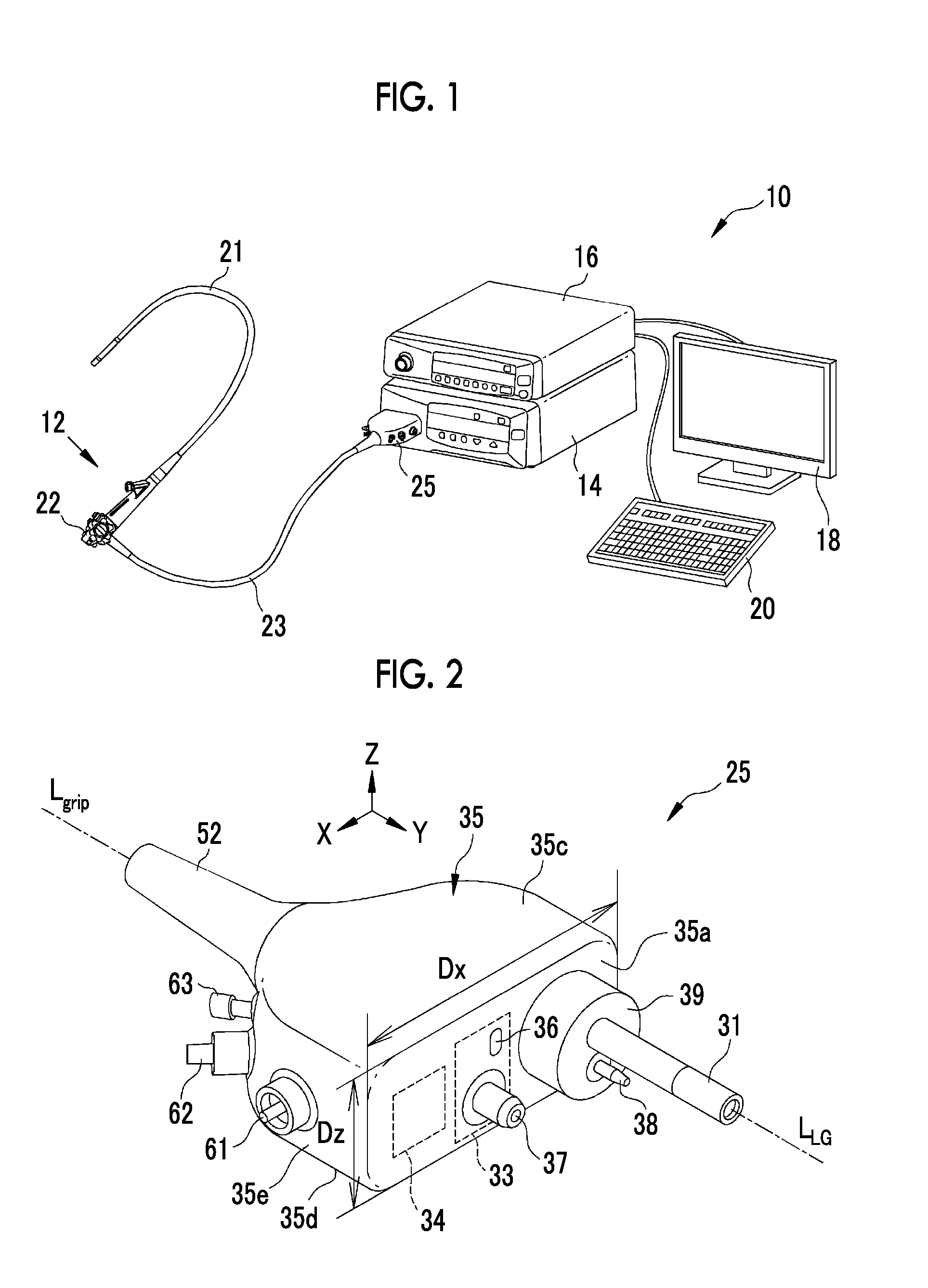
The present application claims priority under 35 U.S.C. §119 to Japanese Patent Application No. 2015-140806, filed on Jul. 14, 2015. Each of the above application(s) is hereby expressly incorporated by reference, in its entirety, into the present application. 1. Field of the Invention The present invention relates to a connector for an endoscope that is connected to a light source device generating illumination light, and an endoscope system. 2. Description of the Related Art A diagnosis, which uses an endoscope system comprising an endoscope, a light source device, and a processor device, is generally made in a medical field. The endoscope includes an insertion part that is inserted into a subject, and images an observation object (a mucous membrane or the like present in the subject) that is irradiated with illumination light generated by the light source device. The processor device generates the image of the observation object by using image signals that are obtained from the imaging of the observation object, and displays the image of the observation object in a monitor. The endoscope is connected to the light source device and the processor device by a cable that is called a universal cable. The universal cable extends from an operation part (a grip section) of the endoscope, and a connector, which is to be connected to the light source device and the processor device, is provided at an end portion of the universal cable. Since the light source device and the processor device are formed separately, the connector generally branches to a connector (hereinafter, referred to as an optical connector) that is optically connected to the light source device and a connector (hereinafter, referred to as an electrical connector) that is electrically connected to the processor device. For example, the optical connector is provided with a light guide part (a light guide, an optical fiber, or the like) that guides illumination light generated by the light source device; and the electrical connector is provided with an electrical contact that sends and receives control signals, image signals obtained from imaging performed by the endoscope, and the like. In recent years, the light source device and the processor device have been connected to each other and there has been a case in which the light source device and the processor device are substantially integrated with each other. In an endoscope system of which the light source device and the processor device are substantially integrated with each other, a connector is electrically connected to the processor device through, for example, the light source device. Accordingly, the connector is formed of a connector in which the optical connector and the electrical connector are integrated with each other. For example, in a connector of an endoscope system disclosed in JP2011-087800A, an optical connector and an electrical connector are integrated with each other and a coil for wirelessly sending and receiving control signals and the like and a coil for wirelessly receiving power to be supplied are provided around a light guide part. For this reason, when the connector of the endoscope system disclosed in JP2011-087800A is connected to a light source device, illumination light emitted from the light source device can be guided by a light guide part and communication of control signals and the like and the supply of power to each part of the endoscope can be performed through the light source device. JP2013-208187A discloses an integrated connector that includes a communication unit (a short-distance wireless transmission unit in JP2013-208187A) provided on the vertically upper side of the light guide part. The connector disclosed in JP2011-087800A is formed in a cylindrical shape as a whole, and the connector disclosed in JP2013-208187A is formed in the shape of a rectangular parallelepiped that is long in a vertical direction (hereinafter, referred to as a vertical type) in a posture in which the connector is connected to the light source device arranged horizontally (hereinafter, referred to as a connection posture). However, connectors having shapes different from the shapes of these connectors are also known. For example, a connector disclosed in JP-H10-155740A is not a connector in which an optical connector and an electrical connector are integrated with each other, but is formed in the shape of a rectangular parallelepiped that is long in a horizontal direction (hereinafter, referred to as a horizontal type) in a connection posture. Further, a connector disclosed in JP2005-312688A is connected to a light source device through an attachment that is called a conduit connection adapter, and is a substantially horizontal type as in JP-H10-155740A in a state in which the conduit connection adapter is connected. Since the optical connector and the electrical connector are integrated with each other as in JP2011-087800A and JP2013-208187A, the structure of the connector in which the optical connector and the electrical connector are integrated with each other is complicated in comparison with a connector in the related art in which the optical connector and the electrical connector are formed separately. Since separate connectors, that is, the optical connector and the electrical connector overlap with each other at one point, the manufacture and maintenance of the connector disclosed in JP2011-087800A are difficult. Furthermore, naturally, an optical member for allowing illumination light to be incident on the light guide part of the connector, a coil for communicating with the connector, a coil for supplying power to the connector, and the like should be disposed so as to be integrated at one point even in the light source device to which the connector is connected. For this reason, manufacture and maintenance are difficult also in this case. Moreover, the light source device is generally formed in the shape of a rectangular parallelepiped of which a vertical length is shortest (a so-called horizontal type). For this reason, when the light guide part and the communication unit (the short-distance wireless transmission unit) are disposed so as to be lined up in the vertical direction as in the vertical type connector disclosed in JP2013-208187A, an optical member for allowing illumination light to be incident on the light guide of the connector and a communication unit (a short-distance wireless transmission unit) for communicating with the connector should be disposed at the smallest portion of the light source device in the vertical direction (a longitudinal direction) so as to be lined up. Accordingly, when a vertical type connector is employed as in JP2013-208187A, the manufacture and maintenance of the light source device are difficult. Further, the light guide part and the communication unit (the short-distance wireless transmission unit) can be disposed in the vertical type connector so as to be separated and lined up in the vertical direction, but the light guide part and the communication unit should be integrated with each other so as to correspond to the height of the light source device. For this reason, actually, the manufacture and maintenance of the vertical type connector are also not easy. An object of the invention is to provide a connector in which an optical connector and an electrical connector are integrated with each other and an endoscope system that are more easily manufactured and subjected to maintenance than the connector and the endoscope system in the related art, such as in JP2011-087800A and JP2013-208187A. A connector according to an aspect of the invention is a connector for an endoscope that is connected to a light source device generating illumination light. The connector comprises a light guide part that guides the illumination light, a wireless communication unit that wirelessly communicates with the light source device, a wireless power receiving unit that wirelessly receives power supplied from the light source device, and a housing that is formed in a flat shape in which a horizontal length is longer than a vertical length in a connection posture where the connector is connected to the light source device. The light guide part, the wireless communication unit, and the wireless power receiving unit are provided on a front surface of the housing, which faces the light source device, so as to be lined up in a horizontal direction. It is preferable that the housing comprises clean connecting caps which are not directly connected to a conduit opened toward the observation object and unclean connecting caps which are directly connected to the conduit opened toward the observation object, and, in a case in which the clean connecting caps are provided on one side in the horizontal direction of the housing in the connection posture, the unclean connecting caps are provided on the other side thereof on which the clean connecting caps are not provided. It is preferable that side surfaces and a rear surface of the housing are curved surfaces curved in at least a horizontal direction in the connection posture and the clean connecting caps and the unclean connecting caps are provided on the side surfaces or the rear surface of the housing. It is preferable that the light guide part is provided at a position offset to one direction in the horizontal direction from a middle of the front surface of the housing in the connection posture. It is preferable that the wireless power receiving unit is provided at a position offset to a direction opposite to the direction in which the light guide part is offset with respect to the middle of the front surface of the housing. It is preferable that the wireless communication unit is provided in the middle of the front surface of the housing in the connection posture. It is preferable that the connector further comprises a grip section that is gripped by a user in a case in which the user connects the connector to the light source device and the grip section protrudes from a rear surface of the housing in the connection posture. It is preferable that the grip section is provided in the rear of the front surface of the housing in a connection direction in which the connector is connected to the light source device. An endoscope system according to another aspect of the invention comprises: a light source device that generates illumination light; the connector including the light guide part guiding the illumination light, the wireless communication unit wirelessly communicating with the light source device, and the wireless power receiving unit wirelessly receiving power supplied from the light source device; and an endoscope that is connected to the light source device by the connector. A housing of the connector is formed in the flat shape in which the horizontal length is longer than the vertical length in the connection posture where the connector is connected to the light source device; and the light guide part, the wireless communication unit, and the wireless power receiving unit are provided on the front surface of the housing, which faces the light source device, so as to be lined up in the horizontal direction. It is preferable that the housing includes clean connecting caps which are not directly connected to a conduit opened toward the observation object and unclean connecting caps which are directly connected to the conduit opened toward the observation object, the light source device includes a connection portion to which the connector is connected and which is provided on a front surface thereof, the connection portion is provided at a position offset to one direction in the horizontal direction from a middle of the front surface of the light source device, the unclean connecting caps are provided on a position of the housing offset to the direction same as the direction in which the connection portion is offset and the clean connecting caps are provided on a position of the housing offset to the direction opposite to the direction in which the connection portion is offset in the connection posture, and the unclean connecting caps are provided on a right side of the housing and the clean connecting caps are provided on a left side of the housing in the connection posture in a case in which the connection portion is provided on a right side of the middle of the front surface of the light source device. It is preferable that the clean connecting caps are provided on a surface of the housing corresponding to a middle of a front surface of the light source device in the connection posture. It is preferable that the clean connecting caps are provided on a surface of the housing corresponding to a middle of the front surface of the light source device in a case in which the number of the clean connecting caps is smaller than the number of the unclean connecting caps and the unclean connecting caps are provided on a surface of the housing corresponding to a middle of the front surface of the light source device in a case in which the number of the clean connecting caps is larger than the number of the unclean connecting caps. According to a connector and an endoscope system of the invention, a housing of the connector is formed in a flat shape in which a horizontal length is longer than a vertical length in a connection posture where the connector is connected to a light source device, and a light guide part, a wireless communication unit, and a wireless power receiving unit are provided on a front surface of the housing, which faces the light source device, so as to be lined up in a horizontal direction. Accordingly, the endoscope system and the connector of the invention are an endoscope system and a connector in which an optical connector and an electrical connector are integrated with each other, but the manufacture and maintenance of the endoscope system and the connector of the invention are easier than in the related art. As shown in The light source device 14 generates illumination light by a semiconductor light source, such as a LED (Light Emitting Diode) or a LD (Laser Diode), or a halogen lamp such as a xenon lamp. In a case in which the connector 25 is connected to the light source device 14, illumination light is incident on the light guide part 31 of the connector 25 and is applied to an observation object from the tip of the insertion part 21. Further, the light source device 14 is electrically connected to the processor device 16, and the connector 25 of the endoscope 12 is also connected to the processor device 16 through the light source device 14 by being connected to the light source device 14. The sending and receiving of control signals, image signals, and the like between the light source device 14 and the connector 25 are wireless communication. For this reason, the light source device 14 transmits control signals and the like, which are wirelessly sent to and received from the connector 25, to the processor device 16. Furthermore, the light source device 14 supplies power, which is used to drive the imaging sensor and the like, to the connector 25, but the supply of this power is also performed wirelessly. The processor device 16 controls the amount and light emitting timing of illumination light emitted from the light source device 14, the operation of the imaging sensor, and the like, and generates an endoscopic image by using image signals that are obtained from the imaging of the observation object irradiated with the illumination light. Further, the processor device 16 is electrically connected to the monitor 18 and the console 20. The monitor 18 displays the endoscopic image generated by the processor device 16, information about the endoscopic image, and the like. The console 20 is a user interface that receives an input operation, such as function setting. As shown in A front surface 35 In this specification, a posture where the connector 25 is correctly connected to the light source device 14 arranged horizontally is a “connection posture”, a vertical direction with respect to the connection posture is referred to as a Z direction, a connection direction in which the connector 25 is connected to the light source device 14 in the connection posture is referred to as a Y direction, and a horizontal direction, which is perpendicular to the Z direction and the Y direction, is referred to as an X direction. The positive side in the Z direction is a vertically upper side; the positive side in the Y direction is a side where the light source device 14 is positioned when viewed from the connector 25; and the positive side in the X direction is a left side (the right side of the connector 25) when the front surface 35 The surface of the housing 35 in the connection posture, which is viewed from the front side of the connector 25 (the positive side in the Y direction), is the front surface 35 A rear portion (a portion corresponding to the negative side in the Y direction) of the housing 35 is formed in the shape of a substantially semi-circular disc. That is, an edge or the like, which clearly divides the right surface 35 A pump connection portion 38 protrudes from a left portion (a portion corresponding to the negative side in the X direction) of the front surface 35 The wireless communication unit 33 includes: a control signal sending/receiving part 36 that wirelessly sends and receives control signals, which control the imaging sensor, and the like, to and from the light source device 14; and an image signal sending part 37 that wirelessly sends image signals, which are obtained from the imaging of the observation object irradiated with the illumination light, to the light source device 14. Wireless communication, which is performed by the control signal sending/receiving part 36 and the image signal sending part 37, is optical communication, and it is preferable that the wireless communication is, for example, near-infrared communication using near-infrared light (light having a wavelength in the range of about 0.7 μm to 2.5 μm). A connection terminal of the control signal sending/receiving part 36 is formed substantially on the front surface 35 The wireless power receiving unit 34 is, for example, a coil (a so-called secondary coil), and receives power that is supplied from a coil (a so-called primary coil) of the light source device 14 by a non-contact power transmission method, such as an electromagnetic induction method or a magnetic field resonance method. In this case, since the wireless power receiving unit 34 is provided in the rear of the front surface 35 The universal cable 23 is connected to the rear portion of the housing 35 (that is the rear surface 35 Further, the connector 25 has a function as a collective connection member (a so-called hub) that connects the endoscope 12 to the light source device 14 and the processor device 16 and also connects various peripheral members used during the use of the endoscope system 10 and the like. For this reason, the connector 25 is provided with a plurality of connecting caps that are connected to these various peripheral members. Specifically, as shown in The second connecting cap 62 is a ventilation connector for a leakage test that checks the air leakage of the insertion part 21. Accordingly, the second connecting cap 62 communicates with the inside of the insertion part 21 and is not connected to a conduit that is opened toward the observation object. Further, the third connecting cap 63 is an S terminal to which an S cord is connected when a high-frequency treatment tool such as an electric scalpel is used. Accordingly, the third connecting cap 63 is not connected to a conduit that is opened toward the observation object. For this reason, the second connecting cap 62 and the third connecting cap 63 are connecting caps that are clean without being contaminated by the mucus and the like of the observation object. Accordingly, unclean connecting caps are not provided and only clean connecting caps are provided on the right surface 35 Meanwhile, as shown in As shown in As shown in A fitting recess 111 to which the fitting protrusion 39 of the connector 25 is fitted is provided at the leftmost end of the connection section 104 (an end corresponding to the negative side in the X direction), and the light guide part-insertion opening 112 is provided in the fitting recess 111. Further, a pump connection portion-insertion opening 113 into which the pump connection portion 38 of the connector 25 is inserted is provided in the fitting recess 111 on the vertically lower side of the light guide part-insertion opening 112. The wireless communication unit 114 of the light source device 14 is provided between the light guide part-insertion opening 112 and the wireless power supply unit 115 in the connection section 104. That is, the wireless communication unit 114 of the light source device 14 is provided in the middle of the connection section 104. The wireless communication unit 114 comprises: a control signal sending/receiving part 116 that wirelessly sends and receives control signals, which control the imaging sensor and the like, to and from the control signal sending/receiving part 36 of the connector 25; and an image signal receiving part 117 that receives image signals from the image signal sending part 37 of the connector 25. Since the image signal sending part 37 of the connector 25 protrudes from the front surface 35 The wireless power supply unit 115 is provided at the rightmost end (the positive side in the X direction) of the connection section 104. The wireless power supply unit 115 is, for example, a coil (a so-called primary coil), and supplies power to the wireless power receiving unit 34 of the connector 25 by a non-contact power transmission method, such as an electromagnetic induction method or a magnetic field resonance method. Since the endoscope 12 is connected to the light source device 14 and the processor device 16 by the connector 25 and the connection section 104 formed as described above, the manufacture and maintenance of the endoscope system 10 are easier than the related art. Specifically, first, since the connector 25 is a horizontal type and the shape of the housing 35 is a flat shape in which a horizontal length Dx is longer than a vertical length Dz, the light guide part 31, the wireless communication unit 33, and the wireless power receiving unit 34 can be disposed on the front surface 35 Likewise, since the connector 25 is a horizontal type and the light guide part 31, the wireless communication unit 33, and the wireless power receiving unit 34 are disposed on the front surface 35 In addition, since the connector 25 is a horizontal type and the light guide part 31, the wireless communication unit 33, and the wireless power receiving unit 34 are disposed on the front surface 35 Further, the connector 25 includes the first connecting cap 61, the second connecting cap 62, and the third connecting cap 63, which are clean and provided on the right surface 35 The reason why the connector 25 includes the first connecting cap 61, the second connecting cap 62, and the third connecting cap 63, which are clean and provided on the right surface 35 Accordingly, in a case in which the light source device 14 of the embodiment is horizontally inverted and a connection section 204 is positioned on the right side of the middle of a front surface 100 of a light source device 214 (the positive side in the X direction) as in the light source device 214 shown in That is, in a case in which there are unclean connecting caps and clean connecting caps, the unclean connecting caps may be provided so as to be concentrated on one of either the left side (the side corresponding to the left surface 35 Furthermore, in the case of the connector 25, the clean connecting caps are three connecting caps, that is, the first connecting cap 61, the second connecting cap 62, and the third connecting cap 63, and the unclean connecting caps are two connecting caps, that is, the fourth connecting cap 64 and the fifth connecting cap 65. For this reason, the number of connecting caps, which protrude to the outside (the negative side in the X direction) more than the light source device 14, of the connector 25 is small. When the number of connecting caps, which protrude to the outside (the negative side in the X direction) more than the light source device 14, is made small as described above, the entire endoscope system 10 is compact even in a state in which the connector 25 is connected to the light source device 14. Accordingly, it is possible to reduce accidents in which persons or articles collide with the connecting caps of the connector 25 in a case in which a cart on which the light source device 14 and the processor device 16 are loaded is moved. As a result, it is possible to more safely and flexibly use the endoscope system 10. From this point of view, it is preferable that clean connecting caps are provided on the surface of the connector corresponding to the middle of the front surface 100 of the light source device 14 in a case in which the number of clean connecting caps is larger than the number of unclean connecting caps and unclean connecting caps are provided on the surface of the connector corresponding to the middle of the front surface 100 of the light source device 14 in a case in which the number of clean connecting caps is smaller than the number of unclean connecting caps. As a result, connecting caps of which the number is smaller are disposed so as to be concentrated on the side to which the connecting caps protrude to the outside more than the light source device 14. Accordingly, for example, in a case in which the connection section 204 is positioned on the left side of the middle of the front surface 100 of the light source device 214 as in the light source device 214 of Meanwhile, since the first connecting cap 61, the second connecting cap 62, the third connecting cap 63, the fourth connecting cap 64, and the fifth connecting cap 65 are provided on the right surface 35 Further, the light guide part 31, the wireless communication unit 33, and the wireless power receiving unit 34, which are disposed on the front surface 35 Likewise, according to the comparison between the wireless communication unit 33 and the wireless power receiving unit 34, the wireless communication unit 33 needs to be more carefully and accurately connected due to the fact that the image signal sending part 37 protrudes from the front surface 35 Accordingly, in a case in which the connection section 204 is positioned at the right end of the light source device 214 as in the light source device 214 of It is preferable that the light guide part 31, the wireless communication unit 33, and the wireless power receiving unit 34 are disposed on the front surface 35 Meanwhile, in the embodiment, each of the connectors 25 and 225 is provided with the first connecting cap 61, the second connecting cap 62, and the third connecting cap 63, which are clean, and the fourth connecting cap 64 and the fifth connecting cap 65 that are unclean. However, the types and the number of the connecting caps, which are provided on the connector 25, are arbitrary. Clean connecting caps other than the first connecting cap 61, the second connecting cap 62, and the third connecting cap 63 may be provided, and unclean connecting caps other than the fourth connecting cap 64 and the fifth connecting cap 65 may be provided. The number of the clean connecting caps may be four or more or may be one or two. Further, clean connecting caps may not be provided in a case in which clean connecting caps are not needed. Likewise, the number of unclean connecting caps may be three or more or may be zero or one. There are provided a connector of which manufacture and maintenance are easy and an endoscope system. A connector is a connector for an endoscope that is connected to a light source device. The connector includes a light guide part that guides illumination light, a wireless communication unit that wirelessly communicates with the light source device, a wireless power receiving unit that wirelessly receives power supplied from the light source device, and a housing that is formed in a flat shape in which a horizontal length is longer than a vertical length in a connection posture where the connector is connected to the light source device. The light guide part, the wireless communication unit, and the wireless power receiving unit are provided on a front surface of the housing, which faces the light source device, so as to be lined up in a horizontal direction. 1. A connector for an endoscope that is connected to a light source device generating illumination light, the connector comprising:
a light guide part that guides the illumination light; a wireless communication unit that wirelessly communicates with the light source device; a wireless power receiving unit that wirelessly receives power supplied from the light source device; and a housing that is formed in a flat shape in which a horizontal length is longer than a vertical length in a connection posture where the connector is connected to the light source device, wherein the light guide part, the wireless communication unit, and the wireless power receiving unit are provided on a front surface of the housing, which faces the light source device, so as to be lined up in a horizontal direction. 2. The connector according to wherein the housing comprises clean connecting caps which are not directly connected to a conduit opened toward an observation object and unclean connecting caps which are directly connected to the conduit opened toward the observation object, and in a case in which the clean connecting caps are provided on one side in the horizontal direction of the housing in the connection posture, the unclean connecting caps are provided on the other side thereof on which the clean connecting caps are not provided. 3. The connector according to wherein side surfaces and a rear surface of the housing are curved surfaces, which are curved in at least a horizontal direction, in the connection posture, and the clean connecting caps and the unclean connecting caps are provided on the side surfaces or the rear surface of the housing. 4. The connector according to wherein the light guide part is provided at a position offset to one direction in the horizontal direction from a middle of the front surface of the housing in the connection posture. 5. The connector according to wherein the light guide part is provided at a position offset to one direction in the horizontal direction from a middle of the front surface of the housing in the connection posture. 6. The connector according to wherein the wireless power receiving unit is provided at a position offset to a direction opposite to a direction in which the light guide part is offset with respect to the middle of the front surface of the housing. 7. The connector according to wherein the wireless communication unit is provided in the middle of the front surface of the housing in the connection posture. 8. The connector according to wherein the wireless communication unit is provided in the middle of the front surface of the housing in the connection posture. 9. The connector according to wherein the wireless communication unit is provided in the middle of the front surface of the housing in the connection posture. 10. The connector according to wherein the wireless communication unit is provided in the middle of the front surface of the housing in the connection posture. 11. The connector according to wherein the wireless communication unit is provided in the middle of the front surface of the housing in the connection posture. 12. The connector according to wherein the wireless communication unit is provided in the middle of the front surface of the housing in the connection posture. 13. The connector according to a grip section that is gripped by a user in a case in which the user connects the connector to the light source device, wherein the grip section protrudes from a rear surface of the housing in the connection posture. 14. The connector according to a grip section that is gripped by a user in a case in which the user connects the connector to the light source device, wherein the grip section protrudes from a rear surface of the housing in the connection posture. 15. The connector according to wherein the grip section is provided in the rear of the front surface of the housing in a connection direction in which the connector is connected to the light source device. 16. An endoscope system comprising:
a light source device that generates illumination light; the connector according to an endoscope that is connected to the light source device by the connector, wherein a housing of the connector is formed in the flat shape in which the horizontal length is longer than the vertical length in the connection posture where the connector is connected to the light source device, and the light guide part, the wireless communication unit, and the wireless power receiving unit are provided on the front surface of the housing, which faces the light source device, so as to be lined up in the horizontal direction. 17. The endoscope system according to wherein the housing includes clean connecting caps which are not directly connected to a conduit opened toward an observation object and unclean connecting caps which are directly connected to the conduit opened toward the observation object, the light source device includes a connection portion to which the connector is connected and which is provided on a front surface thereof, the connection portion is provided at a position offset to one direction in the horizontal direction from a middle of the front surface of the light source device, the unclean connecting caps are provided on a position of the housing offset to the direction same as the direction in which the connection portion is offset and the clean connecting caps are provided on a position of the housing offset to the direction opposite to the direction in which the connection portion is offset in the connection posture. 18. The endoscope system according to wherein the clean connecting caps are provided on a surface of the housing corresponding to the middle of the front surface of the light source device in the connection posture. 19. The endoscope system according to claim17,
wherein the number of the clean connecting caps is larger than the number of the unclean connecting caps, and the clean connecting caps are provided on a surface of the housing corresponding to the middle of the front surface of the light source device. 20. The endoscope system according to claim17,
wherein the number of the clean connecting caps is smaller than the number of the unclean connecting caps, and the unclean connecting caps are provided on a surface of the housing corresponding to the middle of the front surface of the light source device.CROSS-REFERENCE TO RELATED APPLICATIONS
BACKGROUND OF THE INVENTION
SUMMARY OF THE INVENTION
BRIEF DESCRIPTION OF THE DRAWINGS
DESCRIPTION OF THE PREFERRED EMBODIMENTS