Dual Ended, Full Form Tooth Generating Gear Cutter and Associated Cutting Insert
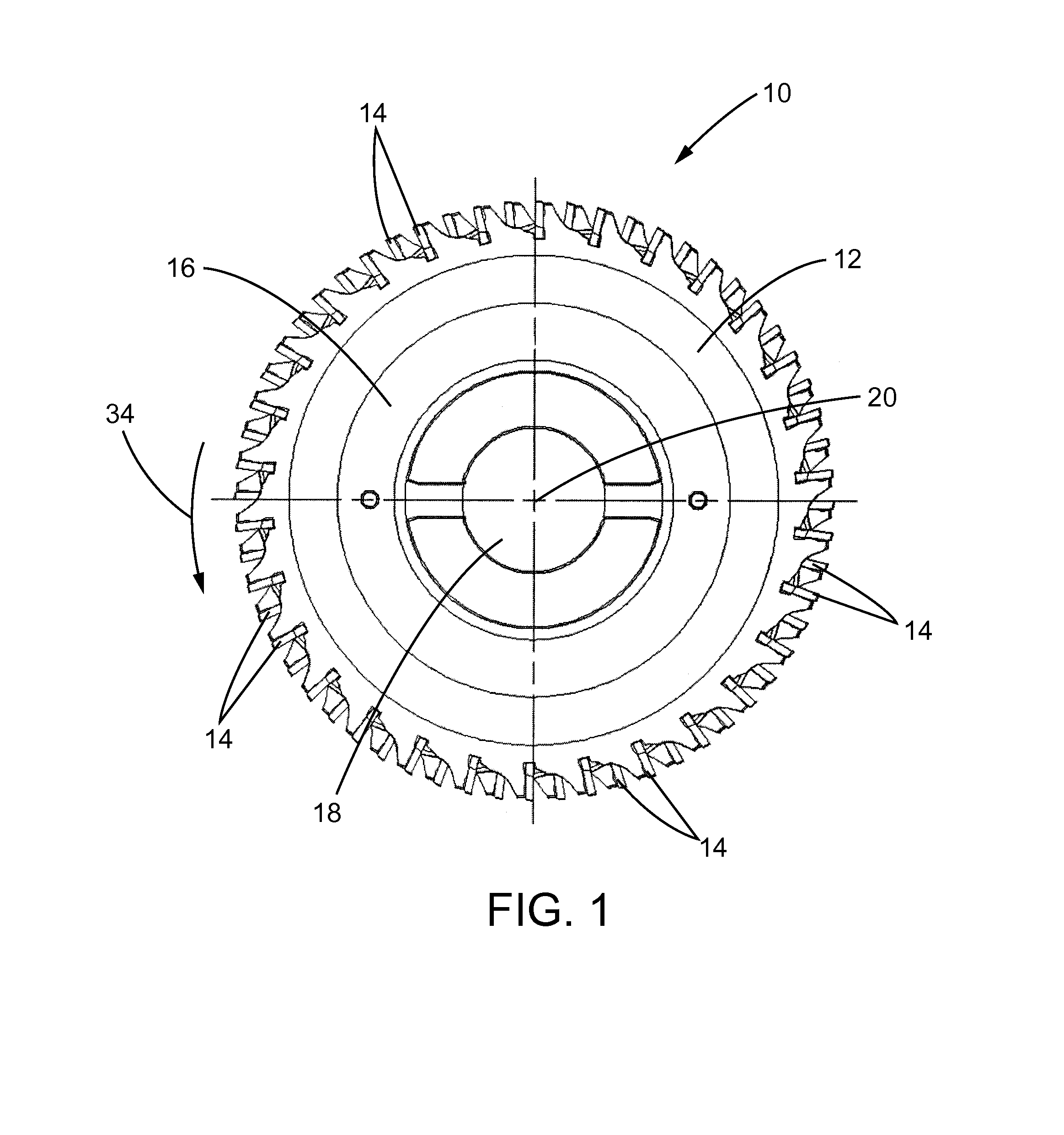
This disclosure relates generally to gear manufacturing and, more particularly, to a gear cutter and associated cutting insert for generating a tooth of a gear. In gear manufacturing, stock is removed from a round blank material to generate the teeth. This is typically done in multiple steps including a roughing step in which stock is initially removed from the gear blank and a finishing step in which the final tooth shape is generated. These different steps often utilize different fixtures and tooling that can require parts to be moved between different machines. This can be time consuming. Moreover, the movement of parts between the different machines may require separate part lifting devices that can increase the cost and complexity of the gear manufacturing process. The switching between different fixtures and tooling for the roughing and finishing steps can also make it more difficult to hold tolerances and maintain consistency in the separate cutting operations which can lead to lower quality, out-of-tolerance gears. One way in which the stock can be removed from the blank material to generate a tooth is using a gear cutter. Gear cutters can include a disc shaped body on which a plurality of cutting inserts are mounted. The body of the gear cutter may be rotated so as to bring the cutting inserts sequentially into engagement with the blank material and thereby cutaway material to form the teeth of the gear. Gear cutters used for finish tooling have multiple overlaid cutting inserts that are typically only capable of generating a single gear tooth at a time. The overlaid cutting inserts used on such gear cutters can be expensive to produce and require significant time and expense to maintain. U.S. Patent Pub. No. 2014/0010606 discloses a milling insert and milling tool that can be used in milling tooth slots of internal and external gear wheels. The disclosed milling tool includes multiple inserts removably mounted on seats formed in a body. Each insert is mounted such that its longitudinal axis extends radially with respect to the body of the milling tool. Moreover, each insert is configured with straight cutting edges. The disclosed milling tool is specifically designed for gear hobbing operations and is incapable of being used in profile milling or non-generative gear milling operations. In one aspect, the disclosure describes a gear cutter for cutting a gap between adjacent teeth of a gear. The gear cutter includes a body member that is configured to be rotatable about a rotational axis. The body member has a perimeter. At least one cutting insert is mounted on the perimeter of the body member and including a forward face, a rear face and a center portion. The cutting insert having a first end and a second end. The first end includes first and second side faces that are configured to converge inwardly toward each other as they extend away from the center portion to a first tip portion that interconnects the first and second side faces. The first and second side faces and the first tip portion intersect with the forward face so as to define a first cutting edge. The second end includes third and fourth side faces that are configured to converge inwardly toward each other as they extend away from the center portion to a second tip portion. The third and fourth side faces and second tip portion intersecting with the forward face so as to define a second cutting edge. Each of the first cutting edge and the second cutting edge has a full involute configuration that matches a desired configuration of the gap between adjacent teeth. In another aspect, the disclosure describes a cutting insert for a gear cutter for cutting a gap between adjacent teeth of a gear. The cutting insert includes a body having a forward face, a rear face and a center portion. The cutting insert has a first end and a second end each of which is configured to cut a full involute gear form geometry. The first end includes first and second side faces that are configured to converge inwardly toward each other as they extend away from the center portion to a first tip portion that interconnects the first and second side faces. The first and second side faces and the first tip portion intersect with the forward face so as to define a first cutting edge. The second end includes third and fourth side faces that are configured to converge inwardly toward each other as they extend away from the center portion to a second tip portion. The third and fourth side faces and second tip portion intersect with the forward face so as to define a second cutting edge. Each of the first cutting edge and the second cutting edge has a full involute configuration that matches a desired configuration of the gap between adjacent teeth. In yet another aspect, the disclosure describes a gear cutter for cutting a gap between adjacent teeth of a gear. The gear cutter includes a body member that is configured to be rotatable about a rotational axis, the body member having a perimeter. At least one cutting insert is mounted to the perimeter of the body member and includes a forward face, a rear face and a center portion. The cutting insert has a first end and a second end each of which is configured to cut a full involute gear form geometry. The first end includes first and second side faces that are configured to converge inwardly toward each other as they extend away from the center portion to a first tip portion that interconnects the first and second side faces. The first and second side faces and the first tip portion intersect with the forward face so as to define a first cutting edge. The second end includes third and fourth side faces that are configured to converge inwardly toward each other as they extend away from the center portion to a second tip portion. The third and fourth side faces and second tip portion intersect with the forward face so as to define a cutting edge. Each of the first cutting edge and the second cutting edge has a full involute configuration that matches a desired configuration of the gap between adjacent teeth. The cutting insert is mounted on the body member such that the first and second cutting edges of the cutting insert extend at a negative rake angle relative to a radial line of the body member. This disclosure generally relates to a gear cutter and an associated cutting insert for generating a tooth of a gear. With particular reference to The gear cutter 10 may include a body member 12 on which a plurality of cutting inserts 14 are supported. As shown in The plurality of cutting inserts 14 may be arranged about the perimeter of the body member 12 of the gear cutter 10. In the illustrated embodiment, the cutting inserts 14 are arranged in axially spaced first and second rows 22, 24 each of which includes a plurality of cutting inserts 14 and extends around the entire perimeter of the body member 12. In each of the first and second rows 22, 24, the plurality of cutting inserts 14 are spaced apart from each other in the circumferential direction of the body member 12 and are evenly distributed about the perimeter of the body member 12. As described in further detail below, each of the cutting inserts 14 may be supported on the body member 12 of the gear cutter 10 so as to protrude in a radial direction outward from the body member 12 (see, e.g., In the illustrated embodiment, the cutting inserts 14 in the first row 22 are arranged in staggered relationship with respect to the cutting inserts 14 in the second row 24 and vice versa as shown, for example, in For receiving the cutting inserts 14, the body member 12 may be configured with a plurality of mounts 26 arranged around the periphery of the body member 12 of the gear cutter 10 to which the cutting inserts 14 may be connected. Moreover, each mount 26 may be configured such that the cutting inserts 14 may be easily removed and replaced, such as when the cutting insert becomes worn after use or when configuring the gear cutter 10 to cut a different type of gear. One way in which the mounts 26 may be configured are as mounting pockets such as shown in Referring to When configured as pocket, each mount 26 may have an associated clamping member 38 which may be operable to help secure the cutting insert 14 in the mount 26. For example, as shown in As best shown in A cutting edge 58 of the cutting insert 14 may be defined by where the first and second side faces 48, 50 and tip portion 52 intersect with the forward face 42 of the cutting insert 14. With such an arrangement, the portion of the cutting edge 58 defined by the first side face 48 may cut one flank of a gear tooth while the portion of the cutting edge 58 defined by the second side face 50 may cut one flank of the next gear tooth. The flanks of the two adjacent gear teeth may form the sides that converge to a bottom of a single gap between adjacent teeth of the gear. As will be appreciated by those skilled in the art, the precise configuration of the forward face 42, rear face 44 and first and second side faces 48, 50 of the cutting insert 14 and the resultant cutting edge 58 may be modified depending upon the particular gear configuration desired to be produced. When received in the respective pocket-type mounts 26 shown, for example, in A further embodiment of a cutting insert 114 and gear cutter 110 according to the present disclosure are shown in As shown in As shown in The gear cutter 10 and associated cutting insert 14 of the present disclosure can be used in the generation of any type of compatible gear. During a gearing cutting operation, the gear cutter 10 may be supported so as to rotate and also move axially relative to the rotary axis of a gear blank. As the gear cutter 10 makes a single axial pass relative to the gear blank, the two rows of cutting inserts 14 on the gear cutter 10 may cut two gaps between adjacent teeth into the gear blank. Thus, the gear cutter 10 can effectively cut two gear teeth into the blank at once in a single pass of the gear cutter 10. Moreover, the use of two axially spaced rows 22, 24 of cutting inserts 14 each configured to cut the full form of a tooth gap allows the gear cutter 10 to be capable of both roughing and finishing of a gear without any change in tooling. This can be a substantial time savings as compared to tooling that can only perform the roughing or finishing step. The resultant gears produced by the gear cutter 10 also can have a higher quality because there is no need to hold tolerances and maintain consistency between separate cutting operations. The use of cutting inserts 14 that are configured to cut the full form of a tooth gap allows spacing between same gap inserts on the gear cutter 10 to be minimized which effectively maximizes the total number of cutting inserts 14 operating on each gap. In particular, as opposed to having separate left flank and right flank cutting inserts, a single cutting insert 14 that cuts the full form of the tooth gap (i.e., simultaneously cuts both flanks) effectively allows more inserts to be arranged around the perimeter of the gear cutter 10 in that each cutting insert cuts both flanks as opposed to every other insert cutting one flank. Maximizing the number of cutting inserts operating on each gap can substantially reduce cycle times of the gear cutter. Configuring the cutting insert 114 such that it is dual ended effectively doubles the utilization of a piece of material, such as carbide, used to create the insert. Once the cutting edge on one end of the insert becomes worn, the cutting insert can be inverted so that the cutting edge on second end of the insert can be used. This provides the cutting insert with a significantly longer life as compared to cutting inserts having a single end that must be removed and recycled when the cutting edge on the single end becomes worn. Arranging the dual ended cutting insert at a negative rake angle may allow for improved chip management as compared to neutrally raked inserts and may eliminate the need to grind clearance into the insert. Accordingly, this disclosure includes all modifications and equivalents of the subject matter recited in the claims appended hereto as permitted by applicable law. Moreover, any combination of the above-described elements in all possible variations thereof is encompassed by the disclosure unless otherwise indicated herein or otherwise clearly contradicted by context. A gear cutter is provided. At least one cutting insert is mounted on a body member. The cutting insert has a first end and a second end, the first end including side faces that are configured to converge inwardly toward each other as they extend to a tip portion, the side faces and the tip portion intersecting with a forward face so as to define a first cutting edge. The second end including side faces that are configured to converge inwardly toward each other as they extend to a tip portion. The side faces and tip portion intersect with the forward face so as to define a second cutting edge. Each of the cutting edges has a full involute configuration that matches a desired configuration of a gap between adjacent teeth of a gear. 1. A gear cutter for cutting a gap between adjacent teeth of a gear comprising:
a body member that is configured to be rotatable about a rotational axis, the body member having a perimeter; and at least one cutting insert mounted on the perimeter of the body member and including a forward face, a rear face and a center portion, the cutting insert having a first end and a second end, the first end including first and second side faces that are configured to converge inwardly toward each other as they extend away from the center portion to a first tip portion that interconnects the first and second side faces, the first and second side faces and the first tip portion intersecting with the forward face so as to define a first cutting edge, the second end including third and fourth side faces that are configured to converge inwardly toward each other as they extend away from the center portion to a second tip portion, the third and fourth side faces and second tip portion intersecting with the forward face so as to define a second cutting edge, each of the first cutting edge and the second cutting edge having a full involute configuration that matches a desired configuration of the gap between adjacent teeth. 2. The gear cutter of 3. The gear cutter of 4. The gear cutter of 5. The gear cutter of 6. The gear cutter of 7. The gear cutter of 8. The gear cutter of 9. The gear cutter of 10. A cutting insert for a gear cutter for cutting a gap between adjacent teeth of a gear comprising:
a body having a forward face, a rear face and a center portion, the cutting insert having a first end and a second end each of which is configured to cut a full involute gear form geometry, the first end including first and second side faces that are configured to converge inwardly toward each other as they extend away from the center portion to a first tip portion that interconnects the first and second side faces, the first and second side faces and the first tip portion intersecting with the forward face so as to define a first cutting edge, the second end including third and fourth side faces that are configured to converge inwardly toward each other as they extend away from the center portion to a second tip portion, the third and fourth side faces and second tip portion intersecting with the forward face so as to define a second cutting edge, each of the first cutting edge and the second cutting edge having a full involute configuration that matches a desired configuration of the gap between adjacent teeth. 11. The cutting insert of 12. The cutting insert of 13. The cutting insert of 14. A gear cutter for cutting a gap between adjacent teeth of a gear, the gear cutter comprising:
a body member that is configured to be rotatable about a rotational axis, the body member having a perimeter; and at least one cutting insert mounted to the perimeter of the body member and including a forward face, a rear face and a center portion, the cutting insert having a first end and a second end each of which is configured to cut a full involute gear form geometry, the first end including first and second side faces that are configured to converge inwardly toward each other as they extend away from the center portion to a first tip portion that interconnects the first and second side faces, the first and second side faces and the first tip portion intersecting with the forward face so as to define a first cutting edge, the second end including third and fourth side faces that are configured to converge inwardly toward each other as they extend away from the center portion to a second tip portion, the third and fourth side faces and second tip portion intersecting with the forward face so as to define a cutting edge, each of the first cutting edge and the second cutting edge having a full involute configuration that matches a desired configuration of the gap between adjacent teeth; wherein the cutting insert is mounted on the body member such that the first and second cutting edges of the cutting insert extend at a negative rake angle relative to a radial line of the body member. 15. The gear cutter of 16. The gear cutter of 17. The gear cutter of 18. The gear cutter of 19. The gear cutter of 20. The gear cutter of TECHNICAL FIELD
BACKGROUND
SUMMARY
BRIEF DESCRIPTION OF THE DRAWINGS
DETAILED DESCRIPTION
INDUSTRIAL APPLICABILITY