DEVICE AND METHOD FOR THE SURFACE MACHINING OF WORKPIECES
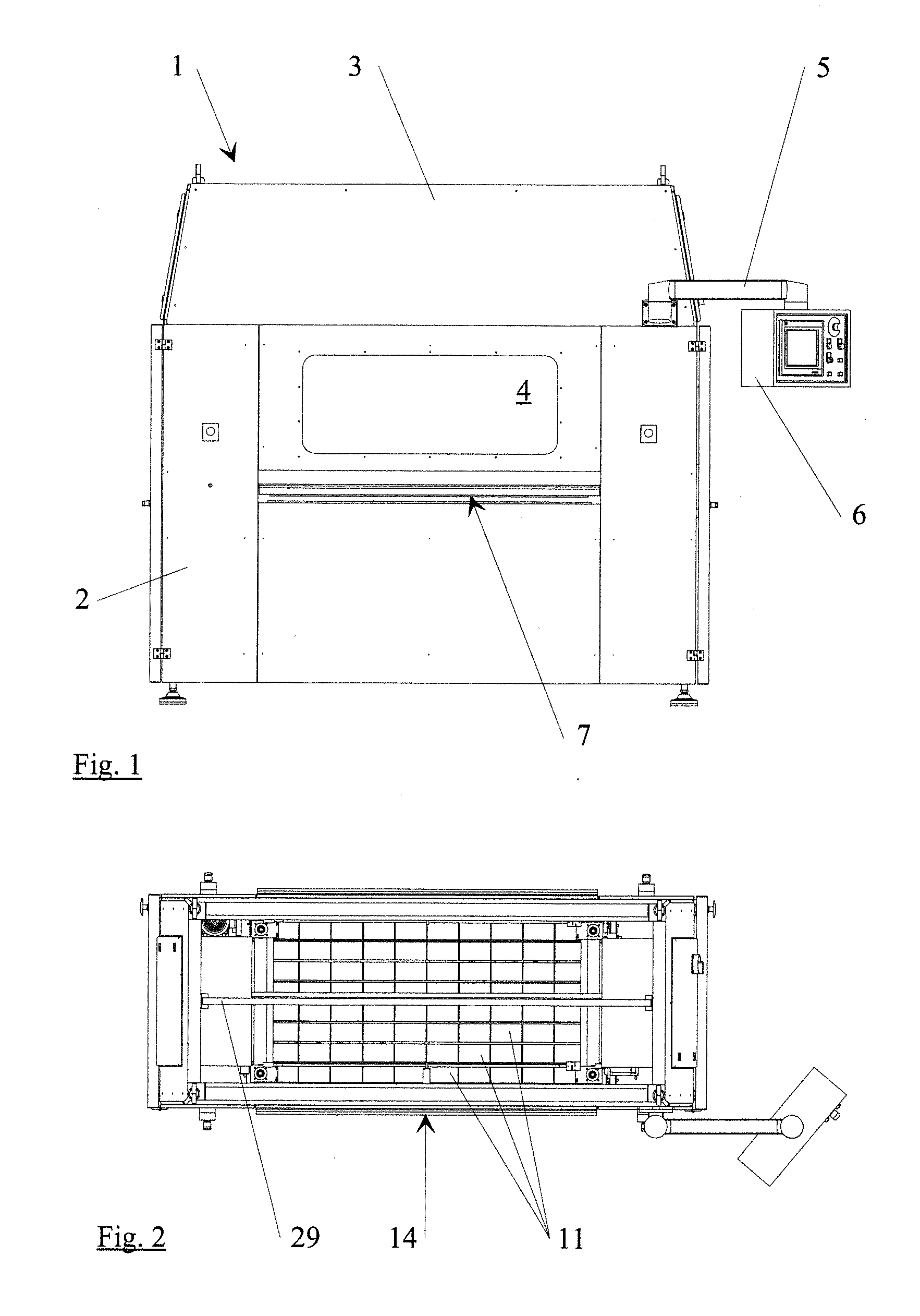
1. Field of the Invention The invention is directed to a device with tools for the surface machining of workpieces, which tools rotate and/or oscillate around axes, and to a method for surface machining, particularly with a device of this kind. 2. Description of the Related Art There are many known devices and methods for machining surfaces of workpieces, for example, for deburring, polishing, texturing, or the like. Generally, brushes of all types, cup brushes, contact brushes or polishing brushes are used as tools particularly with workpieces extending substantially in two dimensions. Further, the devices used in manufacturing technology generally have a plurality of tools which are mostly arranged in a row to machine a workpiece. The known devices are usually adapted very specifically to their intended use and are accordingly suited only for determined tools and workpieces. In view of the foregoing, it is an object of the invention to provide a device and a method for surface machining which offer a number of possibilities for use. In accordance with one aspect of the invention, the above set of problems may be solved using a device having tools for the surface machining of workpieces, which tools rotate and/or oscillate around axes, in which two tool holders are arranged, one behind the other, in a direction of passing of a workpiece, wherein every tool holder has at least one tool, the tool holders are movable in a common plane in opposite directions transverse to the direction of passing of the workpiece, and the maximum machining width of the device corresponds to the sum of the widths of the machining areas defined by the tools transverse to the direction of passing. The device according to this aspect of the invention has many advantages. By providing tool holders, it becomes possible to clamp a wide variety of tools for the surface machining of workpieces. Further, each tool holder preferably has its own drive for the at least one tool so that the tool can be driven at an optimal speed or frequency. Brush forces that occur can also be safely contained. In technical respects relating to manufacture and process, advantages result from the fact that the tool holders are movable in opposite directions in a common plane transverse to the direction of passing of the workpiece, particularly in connection with the step by which the maximum machining width of the device corresponds to the sum of the widths of the machining areas defined by the tools transverse to the direction of passing, as will be explained more fully in the following. Further, it can be provided in a constructively simple manner that the tool holders are movable in guides at a common carrier and that the distance of the carrier relative to a machining plane of the workpiece can be adjusted. Accordingly, there is no need for an elevational adjustment of the tools. Rather, the elevational adjustment of the tool holders and, therefore, an adaptation to the utilized tools and workpieces, is carried out jointly with the carrier. It is conceivable to move the tool holders in opposite directions transverse to the direction of passing pneumatically by pistons, providing the common carrier allows the tool holders to be arranged on a circulating belt with a drive. This belt is preferably a toothed belt. In a constructional elaboration it is further provided that every tool holder has a plurality of tools arranged in a row transverse to the direction of passing of the workpiece. The tools of a tool holder can preferably have a common drive. The device according to an aspect of the invention allows a surface machining of a workpiece from below as well as from above and a simultaneous surface machining of opposite sides of the workpiece in case of a twofold arrangement of components. In particular, the quality of the surface machining is also exceptionally high when it is further provided that the tool holders oscillate transverse to the direction of passing during the surface machining. Machining gaps on the surface are reliably prevented in this way. It can further be provided that the tool holders oscillate synchronously in opposite directions, particularly when the tool holders are arranged at a circulating belt with a drive at a common carrier. Accordingly, the synchronism takes place automatically. To utilize the full machining width of the device, the tool holders with the tools are arranged one behind the other so as to be offset in direction of passing relative to a center plane. Since the inner tools generally wear faster than those located on the outside, it is provided, in case of tools working at an offset transverse to the center plane, to change the offset of the tool holders when the inner tools wear. A uniform wear of the tools is ensured in this way. It is further provided that the axes of the tools of the two tool holders are arranged to provide for rotation and/or oscillation in opposite directions. This is advantageous particularly when it is provided that the tool holders are positioned one directly behind the other during the surface treatment. Accordingly, while the machining width is halved, as it were, the intensity of the surface machining is doubled and the quality is enhanced correspondingly. Other objects and features of the present invention will become apparent from the following detailed description considered in conjunction with the accompanying drawings. It is to be understood, however, that the drawings are designed solely for purposes of illustration and not as a definition of the limits of the invention, for which reference should be made to the appended claims. It should be further understood that the drawings are not necessarily drawn to scale and that, unless otherwise indicated, they are merely intended to conceptually illustrate the structures and procedures described herein. The device and the method according to the invention will be described more fully with reference to the drawings which merely show an embodiment example. In the drawings: The device 1 according to A slot-like inlet opening 7 and outlet opening 8, respectively, are provided on the front side and back side of the housing 2 for workpieces extending substantially two-dimensionally. These workpieces can be fed manually or mechanically, and transporting in the device 1 is carried out by transporting rolls 10 (see Surface-elastic pressing rolls 11 (see, for example Tools 12, 13—see The tool holders 15, 16 are movable in a common plane transverse to the direction of passing 14, for which purpose the tool holders 15, 16 are connected to a common carrier 21 via two linear guides 22, 23 in each instance (See The common carrier 21 of the tool holders 15, 16 is vertically adjustable for different dimensionings of the workpieces and/or tools. To this end, mechanical actuators 27, 28 (see Different operating methods of the device 1 are explained further referring to the top views in The approximately central connection of the tool holders 15, 16 to the toothed belt 26 allows the outer tools 30, 31 to move far out of the working region and, accordingly, enables a simple exchange. The offset of the tool holders 15, 16 is changed for exchanging the inner tools 32, 33 with respect to the direction of passing 14. Alternatively, the tool holders 15, 16 according to This is true particularly when the two tool holders 15, 16 oscillate in opposite directions according to the double arrow and the tools also rotate and/or oscillate in opposite directions. Thus, while there have been shown and described and pointed out fundamental novel features of the invention as applied to a preferred embodiment thereof, it will be understood that various omissions and substitutions and changes in the form and details of the devices illustrated, and in their operation, may be made by those skilled in the art without departing from the spirit of the invention. For example, it is expressly intended that all combinations of those elements and/or method steps which perform substantially the same function in substantially the same way to achieve the same results are within the scope of the invention. Moreover, it should be recognized that structures and/or elements and/or method steps shown and/or described in connection with any disclosed form or embodiment of the invention may be incorporated in any other disclosed or described or suggested form or embodiment as a general matter of design choice. It is the intention, therefore, to be limited only as indicated by the scope of the claims appended hereto. A device for surface machining of a workpiece includes: a plurality of tools configured to rotate and/or oscillate around axes; and two tool holders, arranged one behind the other in a direction of passing of the workpiece. Each tool holder has at least one tool, the two tool holders being movable in a common plane in opposite directions transverse to the direction of passing of the workpiece. A maximum machining width of the device corresponds to a sum of the widths of machining areas defined by the tools transverse to the direction of passing of the workpiece. 1. A device for surface machining of a workpiece, the device comprising:
a plurality of tools configured to rotate and/or oscillate around axes; and two tool holders (15, 16), arranged one behind the other in a direction of passing (14) of the workpiece, each tool holder (15, 16) having at least one tool (12, 13), the two tool holders (15, 16) being movable in a common plane in opposite directions transverse to the direction of passing (14) of the workpiece, and wherein a maximum machining width of the device (1) corresponds to a sum of the widths of machining areas defined by the tools (12, 13) transverse to the direction of passing (14) of the workpiece. 2. The device according to 3. The device according to a circulating belt (26) at which the two tool holders (15, 16) are arranged; and a drive (25) configured to drive the circulating belt (26). 4. The device according to 5. The device according to 6. A method for surface machining of a workpiece using a device according to carrying out the surface machining with tools in the two tool holders (15, 16); rotating and/or oscillating the tools around axes of the tools; arranging the two tool holders (15, 16), which are displaceable transverse to a direction of passing (14) of the workpiece, one behind the other in the direction of passing (14) of a workpiece, wherein the width of every machining area defined by the tools (12, 13) transverse to the direction of passing (14) of the workpiece amounts to one half of a maximum machining width of the device (1); and oscillating the two tool holders (15, 16) transverse to the direction of passing (14) of the workpiece during the surface machining. 7. The method according to 8. The method according to 9. The method according to 10. The method according to BACKGROUND OF THE INVENTION
SUMMARY OF THE INVENTION
BRIEF DESCRIPTION OF THE DRAWINGS
DETAILED DESCRIPTION OF THE PRESENTLY PREFERRED EMBODIMENTS