Joint Seal System & Method
Applicant states that this utility, non-provisional patent application claims priority from and is a continuation-in-part of pending non-provisional U.S. patent application Ser. No. 12/359,163 filed on Jan. 23, 2009 which claimed benefit of provisional U.S. Pat. App. No. 61/062,383 filed on Jan. 25, 2008. Applicant states that this utility, non-provisional patent application also claims priority from pending provisional U.S. Pat. App. No. 62/258,511 filed on Nov. 22, 2015. All of the preceding applications are incorporated by reference herein in their entireties. The present invention relates to duct work for handling various types of gases. More particularly, the present invention is especially useful in providing an air-tight joint between two duct sections. No federal funds were used to develop or create the invention disclosed and described in the patent application. Not Applicable Double-walled chimneys are known in the art, one example of which is disclosed in the U.S. Pat. No. 3,902,744 to Stone and prior art cited therein. The basic construction involves inner and outer concentric pipes affording an annular insulating space between them. Fundamentally, the assembly or erection of the chimney proceeds with coaxial, end-to-end stacking of, say, a pair of inner pipes, the meeting ends of which are radially outwardly flanged to receive an inner annular ring which clamps the pipes together. Another example of a double-walled chimney is disclosed in U.S. Pat. No. 4,724,750, which is incorporated by reference herein. These and other prior art references show that it is known in the art to fabricate corresponding flanges on two adjacent sections at the interface thereof. The flanges are typically transverse to the basic axis of the chimney section. Typically an annular ring is placed over the junction of the two corresponding flanges to better seal the chimney. Although these flanged chimney sections are well known when the cross-sectional shape of the chimney is circular or angular (such as rectangular, square, etc.), the prior art does not disclose a flanged chimney section or corresponding connection system for chimneys with a cross-sectional area that is rounded but non-circular. One such rounded but non-circular shape is often referred to as “obround.” As used herein, “obround” is defined as a shape consisting of two semicircles connected by parallel lines tangent to their endpoints. The accompanying drawings, which are incorporated in and constitute a part of this specification, illustrate embodiments and together with the description, serve to explain the principles of the methods and systems. Before the present methods and apparatuses are disclosed and described, it is to be understood that the methods and apparatuses are not limited to specific methods, specific components, or to particular implementations. It is also to be understood that the terminology used herein is for the purpose of describing particular embodiments only and is not intended to be limiting. As used in the specification and the appended claims, the singular forms “a,” “an,” and “the” include plural referents unless the context clearly dictates otherwise. Ranges may be expressed herein as from “about” one particular value, and/or to “about” another particular value. When such a range is expressed, another embodiment includes from the one particular value and/or to the other particular value. Similarly, when values are expressed as approximations, by use of the antecedent “about,” it will be understood that the particular value forms another embodiment. It will be further understood that the endpoints of each of the ranges are significant both in relation to the other endpoint, and independently of the other endpoint. “Optional” or “optionally” means that the subsequently described event or circumstance may or may not occur, and that the description includes instances where said event or circumstance occurs and instances where it does not. Throughout the description and claims of this specification, the word “comprise” and variations of the word, such as “comprising” and “comprises,” means “including but not limited to,” and is not intended to exclude, for example, other components, integers or steps. “Exemplary” means “an example of” and is not intended to convey an indication of a preferred or ideal embodiment. “Such as” is not used in a restrictive sense, but for explanatory purposes. Disclosed are components that can be used to perform the disclosed methods and apparatuses. These and other components are disclosed herein, and it is understood that when combinations, subsets, interactions, groups, etc. of these components are disclosed that while specific reference of each various individual and collective combinations and permutation of these may not be explicitly disclosed, each is specifically contemplated and described herein, for all methods and apparatuses. This applies to all aspects of this application including, but not limited to, steps in disclosed methods. Thus, if there are a variety of additional steps that can be performed it is understood that each of these additional steps can be performed with any specific embodiment or combination of embodiments of the disclosed methods. The present methods and apparatuses may be understood more readily by reference to the following detailed description of preferred aspects and the examples included therein and to the Figures and their previous and following description. Corresponding terms may be used interchangeably when referring to generalities of configuration and/or corresponding components, aspects, features, functionality, methods and/or materials of construction, etc. those terms. Before the various aspects of the present disclosure are explained in detail, it is to be understood that the disclosure is not limited in its application to the details of construction and the arrangements of components set forth in the following description or illustrated in the drawings. The present disclosure is capable of other embodiments and of being practiced or of being carried out in various ways. Also, it is to be understood that phraseology and terminology used herein with reference to device or element orientation (such as, for example, terms like “front”, “back”, “up”, “down”, “top”, “bottom”, and the like) are only used to simplify description, and do not alone indicate or imply that the device or element referred to must have a particular orientation. In addition, terms such as “first”, “second”, and “third” are used herein and in the appended claims for purposes of description and are not intended to indicate or imply relative importance or significance. Referring now to the drawings, wherein like reference numerals designate identical or corresponding parts throughout the several views, The sections 20, 30 may be obround in shape, which is best shown at least in Referring still to Various aspects of a junction between the first section 20 and the second section 30 is shown in detail in In an aspect, a V-band 40 may be placed over the flange interface 36. A V-band 40, as shown in Again, although not shown in Additional aspects of a chimney system 10 are shown In the insulated chimney system 50 each inner shell 55 and an outer shell 56 may be substantially the same shape for a given insulated chimney section 51, although the periphery of the outer shell 56 generally will be greater than that of the inner shell 55. As previously mentioned, each inner shell 55 of the insulated chimney system 50 may be substantially the same as each section 20, 30 of the chimney system 10 described in detail above in that an inner shell flange 55 In the insulated chimney system 50, a predetermined amount of insulation 52 may be positioned between the inner shell 55 and the outer shell 56. The distance between the inner shell 55 and outer shell 56 may be determined by the length of the spacer clips 53, which spacer clips 53 may extend from the inner shell 55 to the outer shell 56. The spacer clips 53 and insulation 52 may be configured so that an air gap (not shown) remains between the insulation 52 and the outer shell 56 if desired. In another aspect, each spacer clip 53 may include a spacer clip inner tab 53 In an aspect shown in To facilitate access to the inner shells 55 during assembly or for maintenance, adjacent outer shells 56 may be formed with a significant space therebetween, as shown in In one aspect of the chimney system 10, the first section 20 and second section 30 may both be comprised of twenty gauge 304 stainless steel. In one aspect of the insulated chimney system 50 the inner shell 55 may be comprised of twenty gauge 304 stainless steel. Typically, an insulation layer may be applied. The longitudinal seams for any section 20, 30 of the chimney system 10, or any inner shell 55 or outer shell 56 of the insulated chimney system 50 may be continuously welded to reduce corrosion and ensure a pressure-tight seal at each seam. Those of ordinary skill in the art will appreciate that other structures and/or methods of manufacture are possible, without limitation unless so indicated in the following claims. The sections 20, 30, V-band 40, V-band clamp 48, spacer clip 53, inner shell 55, and outer shell 56 may be made from twenty gauge 304 stainless steel, higher or lower chrome steels, or any other material known to those skilled in the art or later developed that is suitable for the application. However, the material chosen in no way limits the scope of the present disclosure unless so indicated in the following claims, and it is contemplated that such specifications may vary based on the particular application for which the chimney system 10 or insulated chimney system 50 is used. As shown in the end view of a section 20, 30 in To better understand the chimney system 10 and insulated chimney system 50, one method of manufacture for a section 20, 30 as pictured and previously described herein will now be described in detail. Those skilled in the art will appreciate that a number of ways to manufacture a section 20, 30 for the chimney system 10 exist, and the specific method used in no way limits the scope of the chimney system 10, sections 20, 30, insulated chimney system 50, or insulated chimney sections 51 unless so indicated in the following claims. Accordingly, the method that follows is but one way to manufacture a chimney section 20, 30. A piece of material, such as stainless steel, may be first cut to the dimensions required to form a sheet 60, which is shown in The sheet 60 is then placed on a metal forming roll (not shown). Each outer section 64 is then formed into a quarter-circle shape. Next, the middle section 68 is formed into a half-circle shape. After this step, the sheet right edge 61 A rigid jig may then be placed around the outer periphery of the section 20, 30 so that the cross-sectional shape of the section 20, 30 is maintained throughout the remainder of the fabrication process. The section 20, 30 may be positioned on a roll forming machine (not shown) set to form a flange 24, 34 of the desired dimensions at one end of the section 20, 30. If a second flange 24, 34 is desired on the other end of the section 20, 30, the jig may be transferred adjacent that end and a flange 24, 34 may be formed thereon using the roll forming machine (not shown). To ensure that the section 20, 30 remains symmetrical along the longitudinal axis thereof throughout the fabrication process, the rotation of the roll forming machine (not shown) may be reversed during the formation of the second flange 24, 34. That is, if the first flange 24, 34 is formed by rotating the section 20, 30 clockwise in the roll forming machine (not shown), the second flange 24, 34 may be formed by rotating the section 20, 30 counter-clockwise in the roll forming machine (not shown). The outer shell 56 for an insulated chimney section 51 may be fabricated in substantially the same manner. However, instead of forming a flange 24, 34 on the roll forming machine (not shown), a different die may be used that forms an outer shell channel 56 Sections 20, 30 (i.e., inner shells 55 when used in an insulated chimney system 50) may be joined with corresponding outer shells 56 through the use of spacer clips 53, many methods of which are well known to those skilled in the art and will therefore not be described in further detail herein. Insulation 52 may also be placed between the inner shell 55 and outer shell 56 so that each insulated chimney section 50 is ready to install before it is exposed to the elements. It is contemplated that machines other than those described for use in the above method may be used to fabricate sections 20, 30, inner shells 55, outer shells 56, or insulated chimney sections 51. Accordingly, the specific machine used to fabricate any element of the chimney system 10 or insulated chimney system 50 in no way limits the scope of the present disclosure unless so indicated in the following claims. Various aspects of a seal 120 are shown in It is contemplated that in an aspect, a joint seal system & method according to the present disclosure may be especially useful when employed with a high-efficiency, commercial boiler vent, wherein a joint seal system & method may be configured to hold pressure in a fluid conduit in order to mitigate and/or eliminate leakage of condensate, flue gasses, and/or other fluid, vapor, and/or gas from a joint between two duct sections (e.g., a flange interface 36) and/or between two sections 20, 30 of a chimney system 10 and/or insulated chimney system 50. Accordingly, it is contemplated that certain aspects of a joint seal system & method may be especially useful at a flange interface 36 of two sections 20, 30 (either insulated or not) having flanges 24, 34, such as those shown in In an aspect, the joint seal system & method may be configured for use with any gas fired appliance listed as Category II, III, or IV or that call for an AL 29-4C vent. Generally, when describing the joint seal system & method below, any section 20, 30 and/or flange 24, 34 may refer to an uninsulated section 20, 30 or any insulated section 51 without limitation unless so indicated. It is contemplated that the joint seal system & method, in conjunction with one or more sections 20, 30, may be installed as a complete system connecting a device (e.g., an appliance) to the outdoors while operating under positive forced draft, negative induced draft, or neutral gravity flow internal pressuring conditions. In applications in which a drain fitting may be required, it is contemplated that it may be advantageous to locate the drain fitting as close to the flue outlet as is possible, but other locations may be used without limitation unless so indicated in the following claims. Installation instructions and an operation and maintenance manual illustrating various aspects of a joint seal system & method is attached hereto and made a part hereof as Appendix A. Referring now to The band 110 may be configured with two angled portions 117 extending from a vertex 117 Referring now to In an aspect, a seal 120 may be positioned at the flange interface 36 of two sections 20, 30. Still referring to It is to be understood that the connector 114 and/or anchor 116 may be configured such that the tension of the band 110 (and in some aspects, consequently the amount by which the seal 120 is compressed) may be adjustable, such that as the band 110 is tightened, the force the band 110 exerts on the abutting flanges 24, 34 increases in at least one dimension, and in two dimensions for certain configurations, wherein a first dimension generally may be normal to the flanges 24, 34 and a second dimension generally may be parallel to the flanges 24, 34. It is contemplated that in some applications, as a force in the first dimension increases, the two flanges 24, 34 may be urged toward one another, which may reduce the propensity for pressure, flue gas, and/or condensate to pass through a flange interface 36. Referring again to It is further contemplated that certain seals 120 may have an optimal amount of deformation to achieve the best seal between two flanges 24, 34, which optimal amount of deformation may depend at least upon the material used to construct the seal 120. The seal 120 may be constructed of any suitable material for the particular application thereof, including but not limited to synthetic materials, cellulosic materials, natural materials, and/or combinations thereof without limitation unless so indicated in the following claims. Furthermore, in certain applications, a seal 120 may be employed in conjunction with another sealant material, such as a liquid, paste, epoxy, and/or other sealant material. In an aspect, the joint seal system & method may be used with an insulated chimney system 50. In such a configuration, a separate exterior band 130 may be positioned around the flange interface 36 and the entire band 110, one example of which is shown in Referring now to Generally, it is contemplated that the fixed flange 142 may be engaged with a flange 24, 34 of a section 20, 30 that is downstream (with respect to an appliance) and that the slip collar flange 144 As depicted in The slip collar 144 may be formed with an anchor and connector, which anchor and connector may be configured in a manner similar to that previously described for the band 110. Generally, the anchor and connector for the slip collar 144 may serve to selectively secure the position of the slip collar 144 with respect to the intermediate section 140. Accordingly, any suitable structure and/or method may be used to selectively secure the position of the slip collar 144 at specific position on the intermediate section without limitation unless so indicated in the following claims. The preceding constraints, examples, and configurations in any of the aspects of the present systems & methods disclosed and described herein are for illustrative purposes only, and are in no way limiting to the scope of any of the systems and/or methods as disclosed herein unless so indicated in the following claims. Furthermore, the various solutions, processes, methods, modules, features, aspects, and/or embodiments disclosed or described herein may be implemented in conjunction with one another or independently from one another. Accordingly, the presence or absence of other subject matter that may be complementary to the present systems and/or methods in no way limits the scope of the present systems and/or methods unless so indicated in the following claims. It should be noted that the present systems and/or methods are not limited to the specific embodiments described herein, but is intended to apply to all similar systems and/or methods for mitigating and/or eliminating leakage between two adjacent duct sections. Modifications and alterations from the described embodiments will occur to those skilled in the art without departure from the spirit and scope of the present systems and/or methods. While the methods and systems have been described in connection with preferred embodiments and specific examples, it is not intended that the scope be limited to the particular embodiments set forth, as the embodiments herein are intended in all respects to be illustrative rather than restrictive. Unless otherwise expressly stated, it is in no way intended that any method set forth herein be construed as requiring that its steps be performed in a specific order. Accordingly, where a method claim does not actually recite an order to be followed by its steps or it is not otherwise specifically stated in the claims or descriptions that the steps are to be limited to a specific order, it is no way intended that an order be inferred, in any respect. This holds for any possible non-express basis for interpretation, including: matters of logic with respect to arrangement of steps or operational flow; plain meaning derived from grammatical organization or punctuation; the number or type of embodiments described in the specification. It will be apparent to those skilled in the art that various modifications and variations can be made without departing from the scope or spirit of the present disclosure. Other embodiments will be apparent to those skilled in the art from consideration of the specification and practice disclosed herein. It is intended that the specification and examples be considered as illustrative only, with a true scope and spirit being indicated by the following claims. A joint seal system and method may include a seal and a band. The seal may be positioned between abutting flanges of two adjacent duct sections. A band may be positioned over the two flanges and the flange interface. The joint seal system and method may be configured to mitigate and/or eliminate leakage of pressure, flue gases, condensate, and/or any other fluid, gas, and/or vapor between abutting flanges of duct sections at a flange interface. 1. A method of connecting a first and a second chimney section, said method comprising:
a. constructing a first section comprising:
i. a body, wherein said body includes first and second portions that oppose one another and are substantially linear in shape, and wherein said body includes third and fourth portions that oppose one another and are curved such that said body has an obround cross-sectional shape; ii. a first flange integrally formed with a first end of said body, wherein said first flange is continuous around the periphery of said first end of said body through said first, second, third, and fourth portions, and wherein said first flange is substantially perpendicular to the main longitudinal axis of said body; iii. a second flange integrally formed with a second end of said body, wherein said second flange is continuous around the periphery of said second end of said body through said first, second, third, and fourth portions, and wherein said second flange is substantially perpendicular to the main longitudinal axis of said body; b. constructing a second section comprising:
i. a body, wherein said body includes first and second portions that oppose one another and are substantially linear in shape, wherein said body includes third and fourth portions that oppose one another and are curved such that said body has an obround cross-sectional shape, and wherein the dimensions of said second section body are substantially the same as those of said first section body; ii. a first flange integrally formed with a first end of said body, wherein said first flange is continuous around the periphery of said first end of said body through said first, second, third, and fourth portions, and wherein said first flange is substantially perpendicular to the main longitudinal axis of said body; c. positioning said first flange of said second section to abut said first flange of said first section to form a flange interface; d. placing a V-band over said flange interface, wherein said V-band comprises:
i. a first angled portion; ii. a second angled portion; and iii. a V-band apex, wherein said V-band apex connects said first angled portion to said second angled portion. 2. The method according to a. a first flat portion, wherein said first flat portion is affixed to said first angled portion, and wherein said first flat portion fits substantially flush to the exterior of said first section body; b. a second flat portion, wherein said second flat portion is affixed to said second angled portion, and wherein said second flat portion fits substantially flush to the exterior of said second section body; and c. a V-band clamp. 3. The method according to 4. The method according to a. an outer shell comprising:
i. a body, wherein the cross-sectional shape of said outer shell body is substantially the same as that of said inner shell body, and wherein the periphery of said outer shell body is greater than that of said inner shell body; ii. an outer shell channel, wherein said outer shell channel is integrally formed with said body; and b. a plurality of spacer clips, wherein each spacer clip extends from said first section body to said outer shell; and c. an insulating material, wherein said insulating material is positioned between said first section body and said outer shell. 5. The method according to 6. The method according to 7. The method according to 8. The method according to 9. The method according to 10. An intermediate section comprising:
a. a first end formed with a fixed flange thereon; b. a second end formed as a free end, wherein a cross-sectional shape and peripheral dimension of said free end is substantially the same as that of said second end without said fixed flange; and, c. a slip collar positioned over a portion of an exterior of said intermediate section between said first and section ends, wherein said slip collar may move along a length of said intermediate section, wherein said slip collar is formed with a slip collar flange thereon, wherein said slip collar is formed with an anchor and a connector, and wherein said anchor and said connector are configured to allow a user to selective secure a position of said slip collar with respect to said first and second ends of said intermediate section. 11. A method of accounting for a variable distance comprising the steps of:
a. fixing a position of a first section, said first section comprising:
i. a body, wherein said body includes first and second portions that oppose one another and are substantially linear in shape, and wherein said body includes third and fourth portions that oppose one another and are curved such that said body has an obround cross-sectional shape; ii. a first flange integrally formed with a first end of said body, wherein said first flange is continuous around the periphery of said first end of said body through said first, second, third, and fourth portions, and wherein said first flange is substantially perpendicular to the main longitudinal axis of said body; iii. a second flange integrally formed with a second end of said body, wherein said second flange is continuous around the periphery of said second end of said body through said first, second, third, and fourth portions, and wherein said second flange is substantially perpendicular to the main longitudinal axis of said body; b. fixing a position of a second section, said second section comprising:
i. a body, wherein said body includes first and second portions that oppose one another and are substantially linear in shape, wherein said body includes third and fourth portions that oppose one another and are curved such that said body has an obround cross-sectional shape, and wherein the dimensions of said second section body are substantially the same as those of said first section body; ii. a first flange integrally formed with a first end of said body, wherein said first flange is continuous around the periphery of said first end of said body through said first, second, third, and fourth portions, and wherein said first flange is substantially perpendicular to the main longitudinal axis of said body; c. positioning an intermediate section between said first fixed section and said second fixed section, said intermediate section comprising:
i. a first end formed with a fixed flange thereon; ii. a second end formed as a free end, wherein a cross-sectional shape and peripheral dimension of said free end is substantially the same as that of said second end without said fixed flange; and, iii. a slip collar positioned over a portion of an exterior of said intermediate section between said first and section ends, wherein said slip collar may move along a length of said intermediate section, wherein said slip collar is formed with a slip collar flange thereon, wherein said slip collar is formed with an anchor and a connector, and wherein said anchor and said connector are configured to allow a user to selective secure a position of said slip collar with respect to said first and second ends of said intermediate section; d. inserting said free end of said intermediate section into said first section such that said free end extends into said first section beyond said first flange of said first section; e. positioning said fixed flange of said intermediate section adjacent said first flange of said second section; f. positioning a seal between said fixed flange of said intermediate section and said first flange of said second section; g. positioning a band around a flange interface formed between said fixed flange of said intermediate section adjacent said first flange of said second section; h. tightening said band such that it engages said fixed flange of said intermediate section adjacent said first flange of said second section to secure the relative positions thereof; i. moving said slip collar toward said first flange of said first section until said slip collar flange is adjacent said first flange of said first section; j. positioning a seal between said slip collar flange of said intermediate section and said first flange of said first section; k. positioning a second band around a flange interface formed between said slip collar flange of said intermediate section adjacent said first flange of said first section; l. tightening said second band such that it engages said slip collar flange of said intermediate section adjacent said first flange of said first section to secure the relative positions thereof; and, m. sealing a space between said slip collar and an exterior surface of said intermediate section. 12. The method according to a. a hinge; b. a first open end; c. a second open end; d. a connector engaged with said first open end; e. an anchor engaged with said second open end; f. a vertex; g. a first angled portion extending outward from said vertex; h. a second angled portion extending outward from said vertex; i. a first flat portion extending away from a distal end of said first angled portion in a direction away from said vertex; and, j. a second flat portion extending away from a distal end of said second angled portion in a direction away from said vertex. 13. The method according to a. a hinge; b. a first open end; c. a second open end; d. a connector engaged with said first open end; e. an anchor engaged with said second open end; f. a vertex; g. a first angled portion extending outward from said vertex; h. a second angled portion extending outward from said vertex; i. a first flat portion extending away from a distal end of said first angled portion in a direction away from said vertex; and, j. a second flat portion extending away from a distal end of said second angled portion in a direction away from said vertex. 14. The method according to a. an outer shell comprising:
i. a body, wherein the cross-sectional shape of said outer shell body is substantially the same as that of said inner shell body, and wherein the periphery of said outer shell body is greater than that of said inner shell body; ii. an outer shell channel, wherein said outer shell channel is integrally formed with said body; and b. a plurality of spacer clips, wherein each spacer clip extends from said first section body to said outer shell; and c. an insulating material, wherein said insulating material is positioned between said first section body and said outer shell.CROSS REFERENCE TO RELATED APPLICATIONS
FIELD OF INVENTION
STATEMENT REGARDING FEDERALLY SPONSORED RESEARCH OR DEVELOPMENT
REFERENCE TO SEQUENCE LISTING, A TABLE, OR A COMPUTER PROGRAM LISTING COMPACT DISK APPENDIX
BACKGROUND
BRIEF DESCRIPTION OF THE FIGURES
DETAILED DESCRIPTION
Listing of Elements
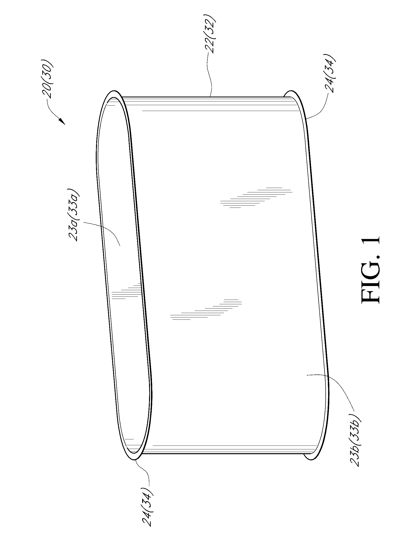
Chimney system 10 First section 20 First section body 22 First section body interior 23a First section body exterior 23b First section flange 24 Second section 30 Second section body 32 Second section body interior 33a Second section body exterior 33b Second section flange 34 Flange interface 36 V-band 40 First flat portion 42a Second flat portion 42b First angled portion 44a Second angled portion 44b V-band apex 46 V-band clamp 48 Insulated chimney system 50 Insulated chimney section 51 Insulation 52 Spacer clip 53 Spacer clip inner tab 53a Spacer clip outer tab 53b Inner shell 55 Inner shell flange 55a Outer shell 56 Outer shell channel 56a Outer band 57 Sheet 60 Sheet right edge 61a Sheet left edge 61b Crease 62 Outer section 64 Inner section 66 Middle section 68 Band 110 Hinge 112 Connector 114 Anchor 116 Slot 116a Angled portion 117 Vertex 117a Flat portion 118 Seal 120 Exterior band 130 Intermediate section 140 Fixed flange 142 Free end 143 Slip collar 144 Slip collar flange 144a DETAILED DESCRIPTION
DETAILED DESCRIPTION OF A JOINT SEAL SYSTEM & METHOD