SEALED BATTERY
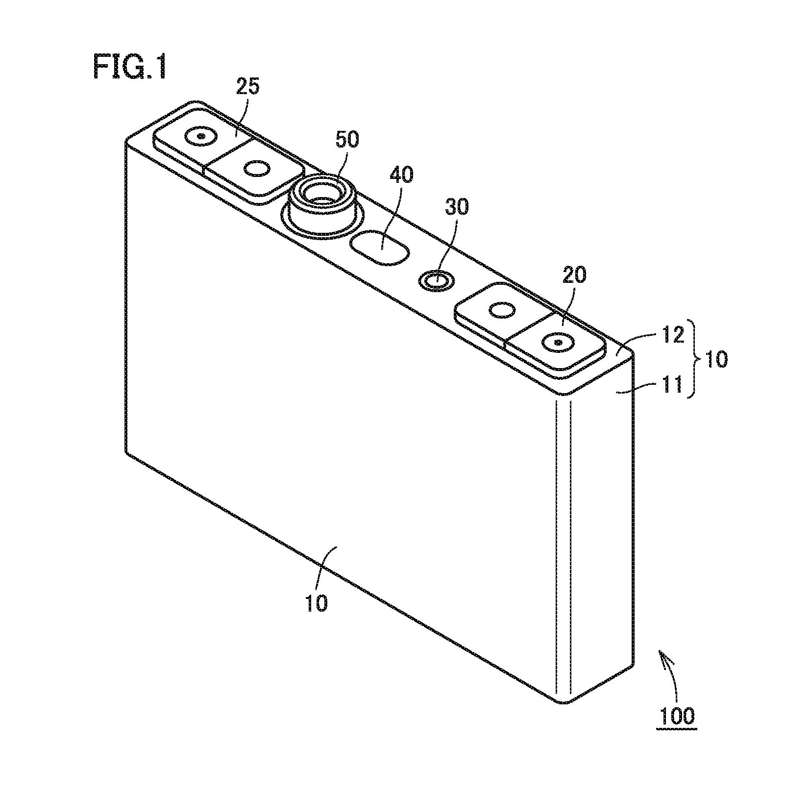
This nonprovisional application is based on Japanese Patent Application No. 2015-197580 filed on Oct. 5, 2015 with the Japan Patent Office, the entire contents of which are hereby incorporated by reference. Field of the Invention The present invention relates to a structure of a sealed battery. Description of the Background Art A sealed battery including a battery element in a sealed casing is disclosed in Japanese Patent Laying-Open No. 2001-185113. Japanese Patent Laying-Open No. 2001-185113 points out that an issue will arise in that when a battery is used as an in-vehicle battery which will be used for long years, the battery internal pressure is increased by gas generation in the battery through charging/discharging or use in high-temperature environments. Employed as a solution therefor is a safety mechanism such as a current-interrupting valve for interrupting a current path when the battery internal pressure rises to a predetermined internal pressure, and an explosion-proof valve which is partly cracked when the battery internal pressure rises to a predetermined internal pressure, thereby preventing a battery container itself from exploding. When the battery internal pressure rises to a certain degree of internal pressure, however, a load is imposed on the safety mechanism, such as the above-described current-interrupting valve and explosion-proof valve, or an airtightly-welded location between a main container and a lid member constituting a battery container, even if these valves do not operate. As a result, there is a concern that the safety mechanism may be reduced in working pressure and/or the weld strength may be reduced because of long-term use. Therefore, the period of use (durable period) set for a sealed battery is short. The present invention was therefore made to solve the problem, and has an object to provide a sealed battery having a structure capable of preventing reduction in working pressure of a safety mechanism and/or reduction in weld strength. This sealed battery is a sealed battery with a battery element housed in a sealed casing. The sealed battery includes a valve brought into a closed state when an internal pressure of a gas in the casing is less than a first pressure, into an open state when the internal pressure is more than or equal to the first pressure and less than a second pressure, and into the closed state when the internal pressure is more than or equal to the second pressure, and a safety mechanism configured to, when the internal pressure reaches a third pressure exceeding the second pressure, operate in accordance with the third pressure. The foregoing and other objects, features, aspects and advantages of the present invention will become more apparent from the following detailed description of the present invention when taken in conjunction with the accompanying drawings. The structure of a sealed battery according to an embodiment will be described below with reference to the drawings. When the number, amount, material, and the like are mentioned, the scope of the present invention is not necessarily limited to that number, amount, material, and the like unless otherwise specified. The same or corresponding parts have the same reference characters allotted, and detailed description thereof may not be repeated. It is intended as of filing to combine features described in embodiments as appropriate. Moreover, the dimensional relationship among length, width, thickness, depth, and the like is varied as appropriate for clarification and simplification of the drawings, and does not indicate an actual dimensional relationship. Referring to Referring to Lid member 12 is provided with an anode terminal 20, a cathode terminal 25, an infusion plug 30, an explosion-proof valve 40, and a valve 50. An electrolyte is introduced into casing 10 through infusion plug 30. Explosion-proof valve 40 has a function of becoming cracked when the internal pressure of casing 10 rises to a predetermined internal pressure to prevent explosion of casing 10 itself. The structure of valve 50 will be described later in detail. Referring to A current-interrupting valve 26 serving as a current-interrupting mechanism and a cathode collecting electrode 27 are connected to cathode terminal 25, similarly to anode terminal 20. Current-interrupting valve 26 interrupts the current path when the internal pressure of casing 10 rises to the predetermined internal pressure. Cathode collecting electrode 27 is connected to a cathode exposed portion 25A of coiled electrode body 60 arranged in casing 10. Current-interrupting valves 21 and 26 may be arranged on either the anode side or the cathode side. The electrolyte, coiled electrode body 60, current-interrupting valves 21 and 26, anode collecting electrode 22, cathode collecting electrode 27, and the like in casing 10 constitute the battery element. Next, referring to Referring to both the drawings, valve 50 is provided to cover an air vent 12 Reverse plate 54 is made of aluminum, and has a thickness of about 0.1 mm to 0.3 mm. Reverse plate 54 has a shape projecting toward air vent 12 In the present embodiment, an annular groove 12 O-ring 56 is housed such that part of its wire diameter protrudes from the surface of lid member 12, thereby coming into contact with the outer peripheral region of reverse plate 54 to improve airtightness. The sealant is not limited to O-ring 56, but may be formed by punching a sheet-shaped sealant circularly. Cap 51 has a shape whose central portion 51 An annular spacer 53 made of metal is arranged between the other end of coil spring 52 and reverse plate 54 in order to make loads on O-ring 56 uniform. Spacer 53 is made of aluminum, SUS or the like, and has a thickness of 0.3 mm to 0.5 mm. An opening 53 Although spacer 53 and reverse plate 54 are made of different members in the present embodiment, spacer 53 having a uniform thickness may be adopted, and reverse plate 54 may be molded integrally with spacer 53 by molding the reverse plate at the central portion of spacer 53 using press molding or the like. The number of components can thus be reduced. Reverse plate 54 is pressed against O-ring 56 by the biasing force of coil spring 52, so that the contact pressure of O-ring 56 is increased. As a result, the state where communication between air vent 12 Next, referring to First, referring to Next, referring to The airtight state of casing 10 is thereby released, so that a gas emission path Y along which air vent 12 When the internal pressure of casing 10 is reduced by gas emission to the outside, spacer 53 and reverse plate 54 are pressed against air vent 12 Next, referring to As a result, when the internal pressure of casing 10 becomes more than or equal to the second pressure (P2), then, reverse plate 54 is reversed toward exhaust hole 51 Thereafter, if the internal pressure rises further to exceed a third pressure (P3), current-interrupting valves 21 and 26 serving as a safety mechanism operate to interrupt the current path. Specifically, the current path between anode terminal 20 and anode collecting electrode 22 is interrupted by current-interrupting valve 21, and the current path between cathode terminal 25 and cathode collecting electrode 27 is interrupted by current-interrupting valve 26. If the internal pressure rises even further, explosion-proof valve 40 serving as a safety mechanism functions and becomes cracked to prevent explosion of casing 10 itself. In the present embodiment, first pressure P1 is less than or equal to about 0.2 MPa, the second pressure (P2) at which reverse plate 54 is reversed is about 0.4 MPa, the third pressure (P3) at which current-interrupting valves 21 and 26 serving as a safety mechanism operate is about 1.2 MPa. In the present embodiment, explosion-proof valve 40 operates upon receipt of a predetermined pressure higher than the third pressure (P3). Now referring to In the normal state (around P1), gas is generated inside sealed battery 100 by conducting charging/discharging, leaving sealed battery 100 at a high temperature, and/or the like. A relief valve usually provided is a mechanism for emitting this gas to the outside. When the internal pressure exceeds pressure P3, for example, the current-interrupting valves (or the explosion-proof valve) serving as a safety mechanism operate, but the safety mechanism does not operate when the internal pressure is less than pressure P3. The internal pressure of sealed battery 100 may rise to P3, and in this state, a load is imposed on a weld and the like. Therefore, the sealed battery will be degraded in reliability if the relief valve is not provided. In the abnormal state of battery casing internal pressure, the internal pressure rises rapidly from P2 to P3. If the relief valve is not provided, the internal pressure rises linearly from P2 to P3 (line B). If the relief valve is provided, gas is emitted, so that the rise in internal pressure becomes slow. As a result, the operating timing of the safety mechanism is delayed, which degrades safety (line C). Moreover, if the working pressure of another safety mechanism is lowered at the initial stage, a malfunction due to degradation in mechanical strength is highly likely to occur. That is, if the relief valve is not provided, damage to the weld and the safety mechanism raises an issue through long-term use although the operation of the safety mechanism is satisfactory. If the relief valve is provided, the reliability in long-term use is improved, but a problem arises in the operation of the safety mechanism. Lowering the working pressure results in the likelihood of malfunctions. On the other hand, in sealed battery 100 provided with valve 50 of the present embodiment, both the advantages of lines B and C can be achieved as indicated by a line A shown in In this way, according to sealed battery 100 provided with valve 50 of the present embodiment, if gas is generated continuously and if the relationship “amount of gas emission <amount of gas generation” holds in the state (shown in Referring to The sealed battery according to the above-described embodiment is preferably a nonaqueous electrolyte secondary battery, and more preferably a rechargeable lithium-ion secondary battery. The anode of the rechargeable lithium-ion battery is preferably implemented by a conventionally-known anode, and can be made of an aluminum foil, for example. The same applies to the anode current collector and the anode terminal, and they are preferably made of aluminum, for example. The cathode of the rechargeable lithium-ion battery is preferably implemented by a conventionally-known cathode, and can be made of a copper foil, for example. The same applies to the cathode current collector and the cathode terminal, and they are preferably made of copper, for example. The separator of the rechargeable lithium-ion battery is preferably implemented by a conventionally-known separator, and is preferably made of PE (polyethylene) or PP (polypropylene), for example. The electrolyte or electrolytic solution of the rechargeable lithium-ion battery is preferably implemented by a conventionally-known electrolyte or electrolytic solution. For example, the electrolyte or electrolytic solution preferably contains lithium salt, such as LiPF6. Although the present invention has been described and illustrated in detail, it is clearly understood that the same is by way of illustration and example only and is not to be taken by way of limitation, the scope of the present invention being interpreted by the terms of the appended claims. A sealed battery with a battery element housed in a sealed casing. The sealed battery includes a valve brought into a closed state when a pressure of a gas in the casing is less than a first pressure P1, into an open state when the pressure is more than or equal to the first pressure P1 and less than a second pressure P2, and into the closed state when the pressure is more than or equal to the second pressure P2, and a safety mechanism configured to, when the internal pressure reaches a third pressure P3 exceeding the second pressure P2, operate in accordance with the third pressure P3. 1. A sealed battery with a battery element housed in a sealed casing, the sealed battery comprising:
a valve brought into a closed state when an internal pressure of a gas in the casing is less than a first pressure, into an open state when the internal pressure is more than or equal to the first pressure and less than a second pressure, and into the closed state when the internal pressure is more than or equal to the second pressure; and a safety mechanism configured to, when the internal pressure reaches a third pressure exceeding the second pressure, operate in accordance with the third pressure. 2. The sealed battery according to the valve is provided to cover an air vent provided in the casing, the valve includes:
a cap at a position opposed to the air vent, the cap provided with an exhaust hole through which the gas is emitted to the outside; a reverse plate housed in the cap and configured to be reversed between a state where the exhaust hole is opened and a state where the exhaust hole is closed; an elastic member housed in the cap and configured to bias the reverse plate toward the air vent; and an annular airtightness holding member provided to surround the air vent and to come into contact with an outer peripheral region of the reverse plate, when the internal pressure is less than the first pressure, the reverse plate is pressed against the airtightness holding member by a biasing force of the elastic member to maintain a state where communication between the air vent and the outside of the casing is interrupted, when the internal pressure is more than or equal to the first pressure and less than the second pressure, the reverse plate moves toward the exhaust hole against the biasing force of the elastic member because of the internal pressure applied to the reverse plate, leaving a gap between the reverse plate and the airtightness holding member to cause the air vent and the exhaust hole to communicate with each other, thereby causing the gas to be emitted to the outside, when the internal pressure is more than or equal to the second pressure, the reverse plate is reversed toward the exhaust hole to close the exhaust hole, thereby stopping emission of the gas through the exhaust hole. 3. The sealed battery according to 4. The sealed battery according to BACKGROUND OF THE INVENTION
SUMMARY OF THE INVENTION
BRIEF DESCRIPTION OF THE DRAWINGS
DESCRIPTION OF THE PREFERRED EMBODIMENTS
Embodiment: Sealed Battery 100
Valve 50
Operation of Valve 50
Another Embodiment: Sealed Battery 100A