PORTHOLE GASKET FOR A PLATE HEAT EXCHANGER, A PLATE PACKAGE AND A PLATE HEAT EXCHANGER WITH SUCH A PORTHOLE GASKET
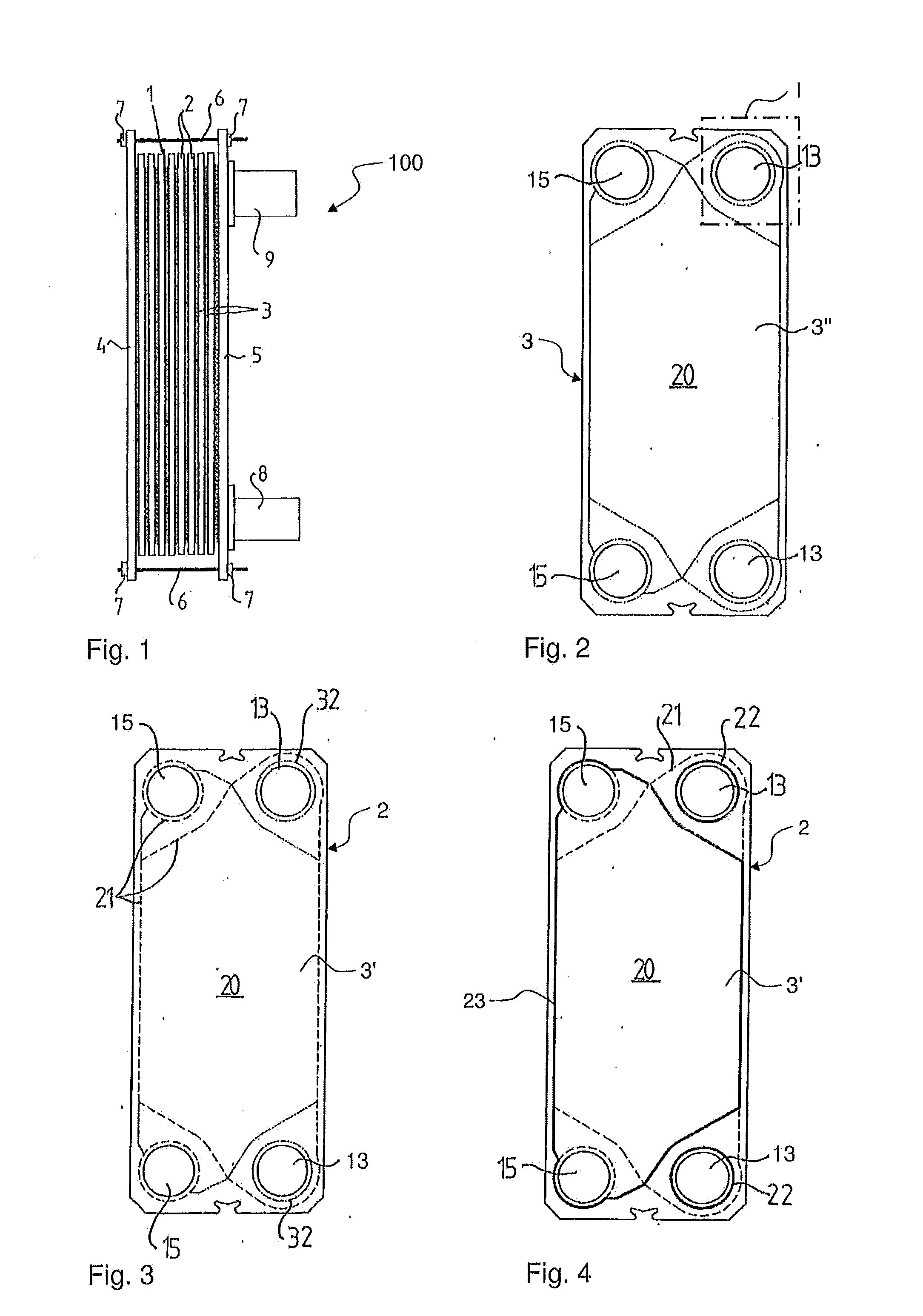
The present invention generally relates to plate heat exchangers, and in particular to a porthole gasket for installation between two adjacent heat exchanger plates of a plate heat exchanger. Plate heat exchangers, PHEs, typically consist of two end plates in between which a heat exchanger plate package is arranged. The plate package typically includes a plurality of heat exchanger plates stacked on each other to define first and second spaces for first and second fluids, where each heat exchanger plate includes portholes that permit fluid communication with the first and second spaces. In one type of well-known PHEs, the so called gasketed PHEs, field and porthole gaskets are arranged between the heat exchanger plates. The field gaskets are typically arranged in field gasket grooves which run along outer edges of the heat exchanger plates while the porthole gaskets typically are arranged in porthole gasket grooves which run along inner edges, more particularly around the portholes, of the heat exchanger plates. The end plates, and therefore the heat exchanger plates, are pressed towards each other whereby the gaskets seal between the heat exchanger plates. In another type of well-known PHEs, the so-called semi-welded plate heat exchangers, the plate package is formed by plate modules, which each comprises two heat exchanger plates welded to each other to define one of the first spaces, the field and porthole gaskets thus being replaced by welds, and the plate modules are stacked, with intermediate field and porthole gaskets arranged in field and ring gasket grooves, respectively, to define the second spaces between them. The semi-welded heat exchangers are frequently used in applications where the first fluid is aggressive or under a significantly elevated pressure, and the second fluid is relatively non-aggressive. The porthole gaskets will be subjected to the first fluid and may have to be manufactured of a high quality material. However, since the porthole gaskets contain a relatively small material volume, this should not have to involve any major increase in costs. For a plate heat exchanger to be leak proof, it may be important that the gaskets are properly positioned in the gasket grooves. The gasket grooves are typically defined by an outer lateral wall, an inner lateral wall and a bottom wall extending there between. The outer and inner lateral walls typically result from pressing of the heat exchanger plates during which operation the plates are provided with a pattern of valleys and ridges. In conventional plate heat exchangers the outer lateral walls of the porthole gasket grooves are intermittent so as to provide, to the porthole gaskets, only periodical support, i.e. support in separated support areas. Thus, there is a risk of the porthole gaskets being displaced, between the support areas, from their proper positioning in the porthole gasket grooves, especially when a pressure prevailing within the porthole gaskets, i.e. inside the portholes, is considerably higher than a pressure prevailing outside the porthole gaskets. As a solution to this problem, WO2004/072570 proposes to re-design the heat exchanger plates so as to make the outer lateral walls of the porthole gasket grooves continuous and thereby capable of providing uninterrupted porthole gasket support. However, there is a need for alternative solutions. It is an objective of the invention to at least partly overcome one or more limitations of the prior art. Another objective is to reduce the risk for fluid leakage in plate heat exchangers with overlapping portholes sealed by porthole gaskets. A still further objective is to reduce the risk for fluid leakage in plate heat exchangers sealed by porthole gaskets located in dedicated ring-shaped gasket grooves with intermittent openings along their outer lateral walls. One or more of these objectives, as well as further objectives that may appear from the description below, are at least partly achieved by means of a porthole gasket, a plate package for a plate heat exchanger and a plate heat exchanger according to the independent claims, embodiments thereof being defined by the dependent claims. A first aspect of the invention is a porthole gasket for installation between two adjacent heat exchanger plates of a plate heat exchanger, the porthole gasket being configured to seal a circumferential region around two overlapping portholes, each of which being formed in a respective one of the two adjacent heat exchanger plates, so as to define a passage for a fluid into or out of the plate heat exchanger. The porthole gasket comprises a ring-shaped portion configured to be compressed between the two adjacent heat exchanger plates while surrounding the overlapping portholes. The porthole gasket further comprises a plurality of projections that protrude from an outer perimeter of the ring-shaped portion and are configured to be compressed between the two adjacent heat exchanger plates so as to support the ring-shaped portion against pressure exerted by the fluid. Compared to a conventional porthole gasket, which has a smooth continuous outer perimeter, the projections will serve to increase the total contact area of the porthole gasket and thus the friction between the porthole gasket and the two adjacent heat exchanger plates when the porthole gasket is compressed between the heat exchanger plates. Thereby, the porthole gasket is more firmly held in place around the two overlapping portholes, reducing the risk for fluid leakage across the circumferential region that is sealed by the porthole gasket. The increased contact area and friction allows the porthole gasket to be firmly held in place if installed, for example, in a ring-shaped gasket groove that has openings in its outer lateral wall. For installation in such a gasket groove, the porthole gasket is suitably configured such that its ring-shaped portion mates with the gasket groove, while its projections mate with and extend through at least a subset of the openings in the outer lateral wall of the gasket groove. These openings may have any distribution along the outer lateral wall. However, the inventive porthole gasket may be installed between any types of adjacent heat exchanger plates, which may or may not be provided with gasket grooves for receiving the porthole gasket. In certain applications, and depending on the design of the porthole gasket and its projections, the porthole gasket may have a sufficient ability to seal the circumferential region around the overlapping portholes and withstand the pressure exerted by the fluid inside the portholes, even if installed and compressed between essentially flat surfaces on the two adjacent heat exchanger plates. It is to be understood that “ring-shaped” does not imply a circular shape, but merely indicates that the ring-shaped portion is configured to surround the overlapping portholes in the circumferential region. Thus, the ring-shaped portion of the porthole gasket may be either circular or non-circular, including regular shapes, such as oval, rectangular, triangular or hexagonal shapes, and irregular shapes. In one embodiment, at least one of the projections comprises a friction-enhancing surface pattern that defines a patterned first surface portion for engaging a first one of the two adjacent heat exchanger plates when the projections are compressed between the two adjacent heat exchanger plates. The provision of such a surface pattern has been found to significantly improve the ability of the porthole gasket to withstand pressure, by further increasing the friction between the porthole gasket and the two adjacent heat exchanger plates. The sealing ability and stability of the porthole gasket may be further improved by optimizing the design of the surface pattern, for example according to one or more of the following embodiments. In one embodiment, the surface pattern defines a patterned second surface portion for engaging a second one of the two adjacent heat exchanger plates when the projections are compressed between the two adjacent heat exchanger plates, the first and second surface portions being arranged on opposite sides of said at least one of the projections. In one embodiment, the surface pattern comprises a plurality of spaced-apart pattern structures, as seen parallel to a normal direction of the patterned first surface portion. It may further be advantageous for the pattern structures to be separated by a gap distance, as seen parallel to the normal direction of the patterned first surface portion, the gap distance being at least half of a smallest dimension of the pattern structures, as seen parallel to the normal direction of the patterned first surface portion. Furthermore, at least a subset of the pattern structures may have rounded ends, as seen parallel to the normal direction of the patterned first surface portion, said rounded ends having a radius which is approximately equal to half of the smallest dimension of the respective pattern structure, as seen parallel to the normal direction of the patterned first surface portion. In one embodiment, the pattern structures comprise protrusions protruding, parallel to the normal direction of the patterned first surface portion, from a bulk portion of said at least one of the projections, to define the patterned first surface portion. Each of the protrusions may have an extent, from the bulk portion and parallel to the normal direction, which is approximately 2.5-5%, or even 2-10%, of a thickness of the bulk portion parallel to the normal direction. In one embodiment, the pattern structures comprise elongated ribs. In one embodiment, said at least one of the projections is elongated and extend in a longitudinal direction away from the outer perimeter of the ring-shaped portion, and at least part of the pattern structures extend essentially transverse to the longitudinal direction. Alternatively or additionally, the sealing ability and stability of the porthole gasket may be further improved by optimizing the design of the projections, for example according to one or more of the following embodiments. One or more of the projections may be connected to the ring-shaped portion by a link portion, which has a smaller material thickness than said one or more of the projections. In one embodiment, at least a subset of the projections are elongated and extend in a longitudinal direction away from the outer perimeter of the ring-shaped portion. It may further be advantageous for the longitudinal direction to be non-perpendicular to the outer perimeter of the ring-shaped portion, for at least one of the projections. The projections may be uniformly distributed around at least a major part of the outer perimeter of the ring-shaped portion. The ring-shaped portion may extend in a geometric plane, and the projections may extend from the ring-shaped portion parallel to the geometric plane. The ring-shaped portion and the projections may extend in the same geometric plane. To facilitate installation of the porthole gasket between the two adjacent heat exchanger plates, the porthole gasket may further comprise an attachment member which protrudes from an inner perimeter of the ring-shaped portion and is arranged to engage with an edge portion of one of the overlapping portholes. In a further embodiment, the porthole gasket comprises a label member which protrudes from the outer perimeter of the ring-shaped portion and is arranged to extend beyond the two adjacent heat exchanger plates so as to be visible externally of the plate heat exchanger. A second aspect of the invention is a plate heat exchanger comprising a porthole gasket of the first aspect. A third aspect of the invention is a plate package for a plate heat exchanger, comprising two adjacent heat exchanger plates and the porthole gasket of the first aspect compressed between the two adjacent heat exchanger plates, each of the two adjacent heat exchanger plates being formed with a porthole, the portholes of the two adjacent heat exchanger plates being overlapping, and the porthole gasket surrounding the portholes. In one embodiment, each of the projections is compressed between a respective pair of opposite engagement surfaces on the two adjacent heat exchanger plates, and wherein each of the projections has a thickness, before compression, which exceeds a distance between the respective pair of opposite engagement surfaces after compression by approximately 10-20%, or even 5-20%. In one embodiment, the ring-shaped portion is located in a ring groove formed in at least one of the two adjacent heat exchanger plates, and at least a subset of the projections are located in channels that are defined by the two adjacent heat exchanger plates to extend away from the ring groove. The respective channel may be formed by single channel groove in one of the heat exchanger plates, or by two mutually aligned channel grooves as defined further below. To further improve the stability of the porthole gasket, one or more of the projections may be fitted in a respective one of the channels that has a non-linear extent away from the ring groove, and each of said one or more of the projections may have an extent that conforms to the non-linear extent of the respective one of the channels. Alternatively or additionally, the ring-shaped portion may be compressed between bottom surfaces of a first ring groove formed in a first one of the two adjacent heat exchanger plates and a second ring groove formed in a second one of the two adjacent heat exchanger plates, the first and second ring grooves being arranged in mutual alignment, and said at least a subset of the projections may be compressed between bottom surfaces of channel grooves, which are formed in the two adjacent heat exchanger plates and arranged in mutual alignment to define said channels. At least one of the two adjacent heat exchanger plates may be formed to extend in at least an intermediate plane, an upper plane and a lower plane, said planes being substantially parallel to each other, wherein the ring-shaped portion may engage said at least one of the two adjacent heat exchanger plates in the intermediate plane, and wherein the projections may engage said at least one of the two adjacent heat exchanger plates in the lower plane. The intermediate plane and the lower plane may coincide. Any one of the embodiments of the first aspect can be combined with the second to third aspects to attain the corresponding technical effects or advantages. Still other objectives, features, aspects and advantages of the present invention will appear from the following detailed description, from the attached claims as well as from the drawings. Embodiments of the invention will now be described in more detail with reference to the accompanying schematic drawings. The plate package 1 is arranged between two end plates 4, 5. The end plates 4, 5 are pressed against the plate package 1 and each other by means of tightening bolts 6 extending through the end plates 4, 5. The tightening bolts 6 include threads and the stack of plate modules 2 may thus be compressed by threading nuts 7 onto the tightening bolts 6 in a manner known per se. In the embodiments disclosed herein, four tightening bolts 6 are implied (of which only two are visible in the figures). It is to be noted that the number of tightening bolts 6 may vary and be different in different applications. The plate heat exchanger 100 also includes two inlet members 8 (only one shown) and two outlet members 9 (only one shown). The inlet and outlet members 8, 9 may be attached to one of the end plates 4, 5 in alignment with respective inlet and outlet ports (not shown) in the end plates 4, 5. These inlet and outlet ports are in turn aligned with inlet and outlet channels that are formed by mutually aligned portholes of the heat exchanger plates 3, as will be described in more detail below. Each heat exchanger plate 3 has a primary side 3′ and a secondary side 3″ ( In the embodiments disclosed herein, the heat exchanger plates 3 in each plate module 2 are so arranged that their secondary sides 3″ face each other and define an inner first space. Further, each pair of two adjacent ones of the plate modules 2 defines a second space. Thus, the second spaces are defined by the primary sides 3′ of two adjacent ones of the heat exchanger plates 3, which adjacent heat exchanger plates are comprised in different, but adjacent, plate modules 2. The heat exchanger plates 3 in each plate module 2 are preferably permanently connected to each other, e.g. by means of welding, brazing or gluing. As seen in A first fluid may thus be introduced via one of the inlet members 8 and the inlet channel defined by the first portholes 13, flow through the first spaces and leave through the outlet channel defined by the first portholes 13 and one of the outlet members 9. A second fluid may be introduced via the other inlet member 8 and the inlet channel defined by the second portholes 15, flow through the second spaces and leave through the outlet channel defined by the second portholes 15 and the other outlet member 9. Each heat exchanger plate 3 is preferably manufactured of a metal sheet, for instance stainless steel, aluminum or titanium, and includes a substantially central heat exchanging surface 20, see Between the plate modules 2, gasket members are installed and compressed to seal the second spaces. As shown in Each of the portholes 13, 15 is defined by a port edge 31, as shown for the first porthole 13 in The following description will focus on the configuration of the porthole gasket 22. As used herein, a peripheral direction of the porthole gasket 22 extends around its perimeter, a radial direction of the porthole gasket 22 extends radially with respect to its center point, and an axial direction of the porthole gasket 22 extends perpendicular to its peripheral and radial directions. Generally, the porthole gasket 22 is an integral component made of a flexible material, such as rubber or a rubber composition. It is understood that when the plate modules 2 have been assembled into the plate package 1 ( The projections 22B serve to increase the contact area of the porthole gasket 22 and thereby increase the friction between the porthole gasket 22 and the adjacent plates 3 when the plate modules 2 are pressed together to compress the porthole gasket 22. To achieve the increase in contact area, each projection 22B has a thickness, before compression, in the axial direction of the porthole gasket 22, which exceeds the total distance between the surfaces of the plates 3 that engage with the projection 22B when the plates 3 are assembled into the plate package 1. This ensures that the projections 22B are compressed between the plates 3 in the plate package 1. In the illustrated embodiment, as understood from In the illustrated example, all projections 22B are elongated to achieve high friction and ensure that the ring portion 22A is not dislocated in the ring groove 32 by the pressure exerted on the ring portion 22A by the first fluid via the first porthole 13. As seen in the section view of In the section view of As seen in Returning to In the example of In the illustrated example, as best shown in As seen in The provision of a surface pattern 40 on the main contact surfaces 22B′, 22B″ has been generally found to increase the friction between the projections 22B and the plates 3 (viz. the bottom surfaces 37) and thereby enhance the ability of the porthole gasket 22 to withstand fluid pressure. The surface pattern 40 may also reduce the impact of fluid being deposited on the bottom surfaces 37 of the channel grooves 36 before assembly, by allowing such fluid to be pressed out between the structures (e.g. ribs) of the pattern 40, when the plate modules 2 are pressed together during assembly. Without the pattern 40, a fluid film might be formed between the projections 22B and the plate 3, resulting in an undesirably low friction there between. Many further variants of the surface pattern 40 are conceivable within the scope of the invention. For example, the pattern 40 may include pattern structures that are essentially linear, oval, circular, zigzag-shaped or arrow-shaped, or any combination thereof. It is also conceivable that at least part of the pattern structures are formed as cuts, grooves or notches in the projection 22B. It is realized that the layout, type and implementation of the pattern structures may be optimized for a particular installation by simulation and testing. In the embodiments shown herein, the ribs 41 protrude from the bulk portion 22B′″ on opposite sides of the projection 22B so as to define the main contact surfaces 22B′, 22B″. It is currently believed that adequate performance, with respect to friction and ability to dispense with fluid deposits, may be achieved by applying a design rule that relates the height of the ribs 41 to the thickness of the bulk portion 22B″. This design rule is further explained in relation to It is currently believed that the provision of pattern structures that extend essentially transverse to the longitudinal direction of the respective projection 22B, such as the ribs 41 in With specific reference to patterns 40 composed of a plurality of parallel transversely extending ribs 41, it is currently believed that the gap distance between the ribs 41 should be at least half the width of the ribs 41 in the longitudinal direction of the projection 22B, E≧D/2 ( Manufacture is also facilitated by providing the respective rib 41 with a radius at its ends 41A, 41B, i.e. the ends 41A, 41B are rounded in plan view ( The surface pattern 40 need not be confined to the main contact surfaces 22B′, 22B″, but may also be circumferential to the projections 22B, so as to also engage with the side walls 38, 39 of the channel grooves 36. This may further enhance the friction between the porthole gasket 22 and the plates 3. For example, not shown, the projection 22B may be provided with a plurality of circumferential flanges that are spaced from each other in the longitudinal direction of the projection 22B. These flanges may e.g. correspond to the ribs 41 on opposite sides of the projection 22B in The above described embodiments of the present invention should only be seen as examples. A person skilled in the art realizes that the embodiment discussed can be varied and combined in a number of ways without deviating from the inventive conception. For example, the above described plate heat exchanger is of parallel counter flow type, i.e. the inlet and the outlet for each fluid are arranged on the same half of the plate heat exchanger and the fluids flow in opposite directions through the first and second spaces between the heat exchanger plates 3. Naturally, the plate heat exchanger could instead be of diagonal flow type and/or a co-flow type. Furthermore, the plate package 1 need not be formed by plate modules 2 that include a number of permanently connected heat exchanger plates 3. Instead, the plate package 1 may be formed as a stack of individual heat exchanger plates 3 and the weld lines disclosed in the foregoing may be replaced by appropriate gasket members, including the porthole gasket 22. Still further, the porthole gasket 22 may be used between any type of heat exchanger plates 3 for sealing a circumferential region around overlapping portholes. Thus, the adjacent plates 3 need not be arranged with their primary sides 3′ facing each other, and the secondary sides 3″ facing each other, but could be arranged with the primary side 3′ of one plate 3 facing the secondary side 3″ of the other plate 3, as in known in the art. It is also possible that the adjacent plates are of different types. It is also possible that all or a subset of the projections 22B are formed without a surface pattern 40, or that the surface pattern 40 is provided on only one of the main contact surfaces 22B′, 22B″. Likewise, all or a subset of the projections 22B may be formed as non-elongated bulbs on the outer perimeter of the ring portion 22A (cf. Still further, the projections 22B need not be uniformly distributed around the ring-shaped portion 22A. Depending on the design of the plate heat exchanger 100, it may be advantageous to ensure that the projections 22B are uniformly distributed around at least a major part of the outer perimeter of the ring-shaped portion 22A. The field and porthole gaskets need not be separated but could be connected to each other or even integrally formed. It should be stressed that a description of details not relevant to the present invention has been omitted and that the figures are just schematic and not drawn according to scale. It should also be said that some of the figures have been more simplified than others. Therefore, some components may be illustrated in one figure but left out on another figure. A porthole gasket is configured to seal a circumferential region around two overlapping portholes in two adjacent heat exchanger plates of a plate heat exchanger, so as to define a passage for a fluid into or out of the plate heat exchanger. The porthole gasket has a ring-shaped portion to be compressed between the two adjacent heat exchanger plates while surrounding the overlapping portholes. The porthole gasket further comprises a plurality of projections that protrude from an outer perimeter of the ring-shaped portion and are configured to be compressed between the two adjacent heat exchanger plates so as to support the ring-shaped portion against pressure exerted by the fluid. A plate package for a plate heat exchanger is configured to include the two adjacent heat exchanger plates and the porthole gasket. 1. A porthole gasket for installation between two adjacent heat exchanger plates of a plate heat exchanger, the porthole gasket being configured to seal a circumferential region around two overlapping portholes, each of which being formed in a respective one of the two adjacent heat exchanger plates, so as to define a passage for a fluid into or out of the plate heat exchanger, wherein the porthole gasket comprises a ring-shaped portion configured to be compressed between the two adjacent heat exchanger plates while surrounding the overlapping portholes, the porthole gasket further comprising a plurality of projections that protrude from an outer perimeter of the ring-shaped portion and are configured to be compressed between the two adjacent heat exchanger plates so as to support the ring-shaped portion against pressure exerted by the fluid. 2. The porthole gasket of 3. The porthole gasket of 4. The porthole gasket of 5. The porthole gasket of 6. The porthole gasket of 7. The porthole gasket of 8. The porthole gasket of 9. The porthole gasket of 10. The porthole gasket of 11. A plate heat exchanger, comprising a porthole gasket according to 12. A plate package for a plate heat exchanger, comprising two adjacent heat exchanger plates and the porthole gasket according to 13. The plate package of 14. The plate package of 15. The plate package of TECHNICAL FIELD
BACKGROUND
SUMMARY
BRIEF DESCRIPTION OF DRAWINGS
DETAILED DESCRIPTION OF EXAMPLE EMBODIMENTS