AIR CONDITIONING DEVICE
The present invention relates to air conditioning devices to which an outdoor unit and indoor units are connected, and, in particular, to an air conditioning device performing oil collecting operation which involves collecting refrigerating machine oil, in a refrigerant circuit, into a compressor when an integrated value of an amount of the refrigerating machine oil accumulated in a refrigerant pipe exceeds a set amount. Typically, a known air conditioning device installed in a building including multiple rooms has a refrigerant circuit to which an outdoor unit and multiple indoor units are connected for providing a vapor compression refrigeration cycle. (See, for example, PATENT DOCUMENT1.) When a compressor of the refrigerant circuit is activated, portion of refrigerating machine oil, stored in the compressor for lubricating a compression mechanism and a bearing in the compressor, flows out of the compressor together with a refrigerant and circulates in the refrigerant circuit. Here, in liquefied portion of the refrigerant in the refrigerant circuit, the refrigerating machine oil flows in the circuit together with the refrigerant; however, in gaseous portion of the refrigerant, portion of the refrigerating machine oil adheres to an interior surface of a heat exchanger tube of a heat exchanger and an interior surface of a refrigerant pipe. Hence, portion of the refrigerating machine oil flowing into the refrigerant circuit fails to return to the compressor, and continuous operation of the compressor reduces an amount of refrigerating machine oil stored in the compressor. Then, when the amount of the stored refrigerating machine oil becomes smaller than a predetermined amount, the compressor tends to develop a lubrication-related malfunction. Thus, this kind of air conditioning device typically performs oil collecting operation which involves forcibly returning, to the compressor, refrigerating machine oil that stays in the refrigerant circuit and fails to return to the compressor. In the oil collecting operation, a flow rate of the gaseous refrigerant is usually increased so that the refrigerating machine oil is caught by the flow of the refrigerant and the caught refrigerating machine oil is sucked into the compressor together with the refrigerant. The oil collecting operation is performed after each elapse of a time period set by a timer. Moreover, of an interconnecting pipe connecting the outdoor unit and an indoor unit, a main pipe is to be connected to the outdoor unit, and a branch pipe is to branch off from the main pipe and be connected to each of the indoor units. The oil collecting operation is also performed in the following case: When the flow rate of the refrigerant in the main pipe is short, the refrigerating machine oil is determined not to return to the compressor and the amount of refrigerating machine oil not returning to the compressor (the amount of lost oil) is calculated. When a value obtained by integrating the calculated values becomes greater than a certain amount, the oil collecting operation is performed. PATENT DOCUMENT 1: Japanese Unexamined Patent Publication No. 2011-257126 The air conditioning device cited in PATENT DOCUMENT1 saves energy by obtaining a required capacity of an indoor unit and controlling an operational capacity of the compressor and a volume of air from an indoor fan, so that a refrigerant temperature (an evaporation temperature or a condensing temperature) of an indoor heat exchanger becomes a certain temperature corresponding to the required capacity. Specifically, the air conditioning device cited in PATENT DOCUMENT1 controls, for example, the operational capacity of the compressor so that a refrigeration cycle is provided at the target evaporation temperature and the target condensing temperature, while changing in the energy-saving operation the target evaporation temperature and the target condensing temperature for every predetermined time period, depending on the required capacity of the indoor unit. However, in the energy-saving operation, a certain branch pipe might have a flow rate of the refrigerant smaller than a lower limit of a flow rate required for oil collection even though the main pipe of the interconnecting pipe has a flow rate of the refrigerant exceeding the lower limit of the flow rate required for the oil collection. Here, the above integrated value is calculated without considering the refrigerating machine oil flowing into the branch pipe. As a result, the calculated integrated value becomes smaller than the amount of the refrigerating machine oil actually flowing out of the compressor. Hence, the compressor is run while the stored amount of the refrigerating machine oil is small, which is likely to cause the compressor to develop a lubrication-related malfunction. Furthermore, not in the energy-saving operation performed with the target evaporation temperature and the target condensing temperature changed but in a normal operation performed with the target evaporation temperature and the target condensing temperature held, the oil collecting operation involves calculating and integrating the amount of lost oil only when the flow rate of the refrigerant in the main pipe does not meet the flow rate required for the oil collection. Hence, when the flow rate of a branch pipe fails to meet the flow rate required for the oil collection even though the flow rate of the refrigerant in the main pipe meets the flow rate required for the oil collection, the amount of oil accumulated in the branch pipe (the amount of lost oil) is not considered. Then, the calculated amount of the refrigerating machine oil is smaller than the amount of the refrigerating machine oil actually flowing out of the compressor, causing the risk that the compressor could run with short of the oil. The present invention is conceived in view of the above problems, and attempts to reduce the risk, in an air conditioning device to which an outdoor unit and indoor units are connected, of a lubrication-related malfunction of a compressor by performing oil collecting operation with appropriate timing. In a first aspect of the present disclosure, an air conditioning device includes: a refrigerant circuit (11) including an outdoor unit (20) and indoor units (40) connected to each other via an interconnecting pipe (71,72); and an operation controller (80) controlling operation of the refrigerant circuit (11), the interconnecting pipe (71,72) including: a liquid main pipe (71 Then, this air conditioning device includes: the oil collection controller (81) including an oil accumulation amount calculator (82) (i) determining that, when a flow rate of a gaseous refrigerant in the gas main pipe (72 In this first aspect, when the flow rate of the gaseous refrigerant in the gas main pipe (72 In a second aspect of the present disclosure according to the first aspect, the oil collection controller (81) includes a reference value storage (83) storing, as a reference value for determining the flow rate of the gaseous refrigerant, a refrigerant state value indicating a state of the gaseous refrigerant corresponding to the preset lower limit flow rate in branch pipe determined for each of the gas branch pipes (72 This second aspect involves determining whether the flow rate of the refrigerant is lower than the preset lower limit flow rate in branch pipe through a comparison between a current value of the refrigerant state value for each gas branch pipe (72 In a third aspect of the present disclosure according to the first aspect, the oil collection controller (81) includes a reference value storage (83) storing, as a reference value for determining the flow rate of the gaseous refrigerant, a refrigerant state value indicating, for one or more air volume levels to be set for each of the indoor units (40), a state of the gaseous refrigerant corresponding to the preset lower limit flow rate in branch pipe, and when calculating the amount of oil accumulated in branch pipe, the oil accumulation amount calculator (82) compares the reference value(s) for the one or more air volume levels with a current value of the refrigerant state value of the gas branch pipes (72 In a fourth aspect of the present disclosure according to the second aspect, the reference value storage (83) has the reference value, of the preset lower limit flow rate in branch pipe of the gas branch pipes (72 These third and fourth aspects involve determining whether the flow rate of the refrigerant is lower than the preset lower limit flow rate in branch pipe through a comparison between a current value of the refrigerant state value for the gas branch pipes (72 In a fifth aspect of the present disclosure according to any one of the second to fourth aspects, the controller (80) performs control in which an evaporation temperature is maintained at a target value (the target evaporation temperature) in cooling operation, the reference value storage (83) stores a set value of the evaporation temperature as the reference value of the preset lower limit flow rate in branch pipe, and the oil accumulation amount calculator (82) calculates the integrated value based on the amount of the refrigerating machine oil accumulated in a gas branch pipe (72 When the energy-saving operation is performed with an evaporation temperature changed in the cooling operation, this fifth aspect involves comparing one of the refrigerant state values (i.e., a current value of the evaporation temperature) with a set value of the evaporation temperature stored as the reference value. If the evaporation temperature is high, required capacity and amount of refrigerant to circulate are small. Thus, calculated is the amount of the refrigerating machine oil accumulated in the gas branch pipe (72 In a sixth aspect of the present disclosure according to any one of the second to fourth aspects, the controller (80) performs control in which a condensing temperature is maintained at a target value (the target condensing temperature) in heating operation, the reference value storage (83) stores a set value of the condensing temperature as the reference value of the preset lower limit flow rate in branch pipe, and the oil accumulation amount calculator (82) calculates the integrated value based on the amount of the refrigerating machine oil accumulated in a gas branch pipe (72 When the energy-saving operation is performed with a condensing temperature changed in the heating operation, this sixth aspect involves comparing one of the refrigerant state values (i.e., a current value of the condensing temperature) with a set value of the condensing temperature stored as the reference value. If the condensing temperature is low, required capacity and amount of refrigerant to circulate are small. Thus, calculated is the amount of the refrigerating machine oil accumulated in the gas branch pipe (72 Note that in each aspect of the present disclosure, the term “target value” is a target evaporation temperature and a target condensing temperature in performing control depending on air-conditioning load in a room. The term “reference value” is a value referenced for determining whether the flow rate of the refrigerant in the gas branch pipes is high or low. The term “set value” is a value of an evaporation temperature and a condensing temperature to be used as the reference value. The term “set amount” is a value for determining whether the oil collection is necessary because of the refrigerating machine oil accumulated in a refrigerant pipe. The above terms are to be used in the above meanings throughout this Description. Even though the flow rate of the gaseous refrigerant in the gas main pipe (72 The second aspect of the present disclosure involves determining whether the flow rate of the gaseous refrigerant is lower than the lower limit flow rate in branch pipe through a comparison between a current value of the refrigerant state value for each gas branch pipe (72 The third and fourth aspects of the present disclosure involve determining whether the flow rate of the refrigerant is lower than the lower limit flow rate in branch pipe through a comparison between a current value of the refrigerant state value for each gas branch pipe (72 When the energy-saving operation is performed with an evaporation temperature changed in the cooling operation, the fifth aspect of the present disclosure involves comparing a current value of the evaporation temperature with a set value of the evaporation temperature stored as the reference value, obtaining the integrated value, and performing the oil collecting operation. Such features make it possible to easily control the oil collecting operation. When the energy-saving operation is performed with a condensing temperature changed in the heating operation, the sixth aspect of the present disclosure involves comparing a current value of the condensing temperature with a set value of the condensing temperature stored as the reference value, obtaining the integrated value, and performing the oil collecting operation. Such features make it possible to easily control the oil collecting operation. Embodiments of the present invention will now be described in detail with reference to the drawings. <Configuration of Air Conditioning Device> The interconnecting pipe (71, 72) includes: a liquid main pipe (71 <Indoor Unit> Each of the indoor units (40) is flush-mounted to or suspended from a ceiling of, for example, a building. Alternatively, the indoor unit (40) is mounted on an indoor wall surface. The indoor units (40) are connected to the outdoor unit (20) via the liquid interconnecting pipe (71) and the gas interconnecting pipe (72), and constitute a part of the refrigerant circuit (11). The indoor unit (40) includes an indoor refrigerant circuit (11 The indoor expansion valve (41) is an electric expansion valve connected to a liquid side of the indoor heat exchanger (42) for, for example, adjusting a flow rate of a refrigerant flowing in the indoor refrigerant circuit (11 The indoor heat exchanger (42) is a cross-fin fin-and-tube heat exchanger including a heat exchanger tube and many fins. In the cooling operation, the indoor heat exchanger (42) functions as an evaporator for the refrigerant to cool indoor air. In the heating operation, the indoor heat exchanger (42) functions as a condenser for the refrigerant to heat the indoor air. Note that, in this embodiment, the indoor heat exchanger (42) is, but not limited to, a cross-fin fin-and-tube heat exchanger. Alternatively, the indoor heat exchanger (42) may be any other type of heat exchanger. The indoor unit (40) includes an indoor fan (43) acting as an air blower for sucking indoor air into the unit, causing the indoor heat exchanger (42) to exchange heat between the sucked air and the refrigerant, and then supplying the air as supply air. The indoor fan (43) is capable of adjusting a volume of air to be supplied to the indoor heat exchanger (42) within a range of a predetermined air volume. In this embodiment, examples of the indoor fan (43) include a centrifugal fan and a multi-blade fan driven by a motor (43 In this embodiment, the indoor fan (43) may operate in an air volume setting mode set with such an input device as a remote control. The air volume setting mode includes: an air volume holding mode setting the volume of air in three kinds of held air volume; namely, low wind supplying the smallest volume of air, high wind supplying the largest volume of air, and middle wind approximately midway between the low wind and the high wind; and an auto air volume mode automatically changing the volume of air between the low wind and the high wind, depending on, for example, a degree of superheat SH and a degree of subcooling SC. Specifically, when a user selects, for example, any one of “low wind”, “middle wind”, and “high wind”, the indoor fan (43) operates in the air volume holding mode holding the volume of air in the low wind. When the user selects “auto”, the indoor fan (43) operates in the auto air volume mode automatically changing the volume of air depending on an operating state. Note that in this embodiment, a fan tap of the indoor fan (43) for the volume of air may be switched between, but not limited to, three stages such as “low wind (L)”, “middle wind (M)”, and “high wind (H)”. Alternatively, the tap may be switched between, for example, ten stages. Moreover, the indoor unit (40) is provided with various kinds of sensors. The liquid side of the indoor heat exchanger (42) is provided with a liquid temperature sensor (44) detecting a temperature of the refrigerant (a refrigerant temperature corresponding to a condensing temperature Tc in the heating operation or an evaporation temperature Te in the cooling operation). A gas side of the indoor heat exchanger (42) is provided with a gas temperature sensor (45) detecting a temperature of the refrigerant. An indoor air inlet side of the indoor unit (40) is provided with an indoor temperature sensor (46) detecting a temperature of the indoor air (an indoor temperature Tr) flowing into the unit. In this embodiment, thermistors are used as the liquid temperature sensor (44), the gas temperature sensor (45), and the indoor temperature sensor (46). Moreover, the indoor unit (40) includes an indoor controller (47) controlling operations of the devices included in the indoor unit (40). The indoor controller (47) includes: an air-conditioning capacity calculator (47 <Outdoor Unit> Provided out of the building, the outdoor unit (20) is connected to the indoor units (40) via the liquid interconnecting pipe (71) and the gas interconnecting pipe (72). Together with the indoor units (40), the outdoor unit (20) constitutes the refrigerant circuit (11). The outdoor unit (20) includes an outdoor refrigerant circuit (11 The compressor (21) is capable of adjusting its operational capacity. In this embodiment, the compressor (21) is a positive displacement compressor driven by a motor (21 The four-way switching valve (22) is for switching a flow direction of the refrigerant. In the cooling operation, in order to cause the outdoor heat exchanger (23) to function as a condenser for the refrigerant to be compressed by the compressor (21) and to cause the indoor heat exchangers (42) to function as an evaporator for the refrigerant to be condensed in the outdoor heat exchanger (23), the four-way switching valve (22) connects (i) a discharge side of the compressor (21) with a gas side of the outdoor heat exchanger (23), and (ii) a suction side of the compressor (21) (specifically, the accumulator (24)) with the gas interconnecting pipe (72). (A cooling operation state: see solid pipes of the four-way switching valve (22) in The outdoor heat exchanger (23) is a cross-fin fin-and-tube heat exchanger for exchanging heat between air as a heat source and the refrigerant. The outdoor heat exchanger (23) functions as a condenser for the refrigerant in the cooling operation, and as an evaporator for the refrigerant in the heating operation. The outdoor heat exchanger (23) has the gas side connected to the four-way switching valve (22) and the liquid side connected to the outdoor expansion valve (38). Note that, in this embodiment, the outdoor heat exchanger (23) is, but not limited to, a cross-fin fin-and-tube heat exchanger. Alternatively, the outdoor heat exchanger (23) may be any other type of heat exchanger. The outdoor expansion valve (38) is an electronic expansion valve provided downstream of the outdoor heat exchanger (23) along the flow of the refrigerant in the refrigerant circuit (11) in the cooling operation to adjust, for example, a pressure and a flow rate of the refrigerant flowing in the outdoor refrigerant circuit (11 The outdoor unit (20) includes an outdoor fan (28) acting as an air blower for sucking outdoor air into the unit, causing the outdoor heat exchanger (23) to exchange heat between the sucked air and the refrigerant, and then ejecting the air out of the outdoor unit (20). This outdoor fan (28) is capable of adjusting a volume of air to be supplied to the outdoor heat exchanger (23). The outdoor fan (28) may be a propeller fan driven by a motor (28 The liquid stop valve (26) and the gas stop valve (27) are provided to connecting ports of external devices and piping (specifically, the liquid interconnecting pipe (71) and the gas interconnecting pipe (72)). The liquid stop valve (26) is provided downstream of the outdoor expansion valve (38) and upstream of the liquid interconnecting pipe (71) along the flow of the refrigerant in the refrigerant circuit (11) in the cooling operation. The liquid stop valve (26) is capable of blocking the flowing refrigerant. The gas stop valve (27) is connected to the four-way switching valve (22). Moreover, the outdoor unit (20) is provided with various kinds of sensors. Specifically, the outdoor unit (20) includes: an inlet pressure sensor (29) detecting an inlet pressure (i.e., a refrigerant pressure corresponding to an evaporating pressure Pe in the cooling operation) of the compressor (21); a discharge pressure sensor (30) detecting a discharge pressure (i.e., a refrigerant pressure corresponding to a condense pressure Pc in the heating operation) of the compressor (21); an inlet temperature sensor (31) detecting an inlet temperature of the compressor (21); and a discharge temperature sensor (32) detecting a discharge temperature of the compressor (21). An outdoor air inlet port of the outdoor unit (20) is provided with an outdoor temperature sensor (36) detecting a temperature (i.e., an outdoor temperature) of the outdoor air flowing into the unit. In this embodiment, thermistors are used as the inlet temperature sensor (31), the discharge temperature sensor (32), and the outdoor temperature sensor (36). Furthermore, the outdoor unit (20) includes an outdoor controller (37) controlling operations of the units included in the outdoor unit (20). As illustrated in Energy-saving control in the cooling operation is provided as described below. First, the indoor controllers (47) of the corresponding indoor units (40) calculate requested evaporation temperatures Ter based on, for example, a temperature difference between an inlet temperature and a set temperature, and transmit the requested evaporation temperatures Ter to the outdoor controller (37). Next, the outdoor controller (37) of the outdoor unit (20) selects the lowest requested evaporation temperature from among the requested evaporation temperatures Ter transmitted from the indoor units (40), and determines the selected temperature to be a target evaporation temperature Tet as a target value for the control. Here, the determined target evaporation temperature Tet is a current value of the evaporation temperature (a current value of the refrigerant state value). Then, this target evaporation temperature determination process is executed at predetermined time intervals (for example, every three minutes) such that the air conditioning device (10) stably operates while saving energy. Note that in the heating operation, the outdoor controller (37) selects the highest requested condensing temperature from among the requested condensing temperatures calculated and transmitted by the indoor units (40), and determines the selected temperature to be a target condensing temperature Tct. Here, the determined target condensing temperature Tct is a current value of the condensing temperature (a current value of the refrigerant state value). As The controller (80) includes an oil collection controller (81). Moreover, the oil collection controller (81) includes an oil accumulation amount calculator (82) and a reference value storage (83). The oil collection controller (81) calculates, at predetermined time intervals, an amount of refrigerating machine oil accumulated in the interconnecting pipe (71,72) during the operation, and integrates the amount calculated for each predetermined time interval. When a value of the integration exceeds a set amount, the oil collection controller (81) performs oil collecting operation for collecting the refrigerating machine oil in the refrigerant circuit (11) into the compressor (21). When the flow rate of a gaseous refrigerant in the gas main pipe (72 The reference value storage (83) stores, as a reference value for determining the flow rate of the gaseous refrigerant, a refrigerant state value indicating a state of the refrigerant corresponding to the preset lower limit flow rate in branch pipe determined for each of the gas branch pipes (72 Moreover, as illustrated in As described above, the controller (80) controls to maintain, the evaporation temperature at the target value during the cooling operation. Then, the reference value storage (83) stores a set value of the evaporation temperature as a reference value of the lower limit flow rate in branch pipe. Furthermore, the oil accumulation amount calculator (82) calculates the integrated value based on the amount of oil accumulated in the gas branch pipe (72 Moreover, the controller (80) controls to maintain the condensing temperature at the target value during the heating operation. Then, the reference value storage (83) stores a set value of the condensing temperature as a reference value of the lower limit flow rate in branch pipe. Furthermore, the oil accumulation amount calculator (82) calculates the integrated value based on the amount of the refrigerating machine oil accumulated in a gas branch pipe (72 <Interconnecting Line> When the air conditioning device (10) is installed in an installation site such as a building, the interconnecting pipe (71,72); namely refrigerant pipes, are installed at the installation site. The interconnecting pipe (71,72) for use vary in length and diameter, depending on installation conditions such as a combination of the outdoor unit (20) and the indoor units (40). Then, when an air conditioning device (10) is newly installed, for example, the air conditioning device (10) needs to be charged with an appropriate amount of refrigerant, depending on installation conditions such as lengths and diameters of the interconnecting pipe (71,72). As can be seen, the indoor refrigerant circuit (11 Described next is operation of the air conditioning device (10). The air conditioning device (10) performs indoor temperature control with respect to each of the indoor units (40) in the cooling operation and the heating operation below. In the indoor temperature control, the indoor temperature Tr is brought closer to a set temperature Ts set by a user with an input device such as a remote control. When the indoor fan (43) is set to the auto air volume mode, the indoor temperature control involves adjusting a volume of air from each indoor fan (43) and an opening of each indoor expansion valve (41) to bring the indoor temperature Tr to the set temperature Ts. When the indoor fan (43) is set to the air volume holding mode, the indoor temperature control involves adjusting an opening of each indoor expansion valve (41) to bring the indoor temperature Tr to the set temperature Ts. Note that the statement “adjusting an opening of each indoor expansion valve (41)” is to control a degree of superheat at an outlet of each indoor heat exchanger (42) in the case of the cooling operation, and to control a degree of subcooling at the outlet of each indoor heat exchanger (42) in the case of the heating operation. <Cooling Operation> Described first is the cooling operation with reference to In the cooling operation, the four-way switching valve (22) is in a state illustrated in the solid pipes in When the compressor (21), the outdoor fan (28), and the indoor fans (43) operate in this state of the refrigerant circuit (11), a low-pressure gaseous refrigerant is sucked into, and compressed by, the compressor (21) to become a high-pressure gaseous refrigerant. After that, the high-pressure gaseous refrigerant is sent through the four-way switching valve (22) to the outdoor heat exchanger (23), exchanges heat with outdoor air to be supplied by the outdoor fan (28), and condenses to become a high-pressure liquid refrigerant. Then, this high-pressure liquid refrigerant is sent through the liquid stop valve (26) and the liquid interconnecting pipe (71) to each indoor unit (40). The high-pressure liquid refrigerant sent to the indoor unit (40) is decompressed by the indoor expansion valve (41) close to the inlet pressure of the compressor (21) to be a refrigerant in a two-phase gas-liquid state, and sent to the indoor heat exchanger (42). The refrigerant then exchanges heat with indoor air in the indoor heat exchanger (42), and evaporates to become a low-pressure gaseous refrigerant. This low-pressure gaseous refrigerant is sent through each gas interconnecting pipe (72) to the outdoor unit (20), and flows through the gas stop valve (27) and the four-way switching valve (22) into the accumulator (24). The low-pressure gaseous refrigerant flowing into the accumulator (24) is sucked into the compressor (21) again. Hence, the air conditioning device (10) performs the cooling operation in which the outdoor heat exchanger (23) functions as a condenser of the refrigerant compressed by the compressor (21) and the indoor heat exchangers (42) functions as evaporators of the refrigerant condensed by the outdoor heat exchanger (23) and then sent through the liquid interconnecting pipe (71) and the indoor expansion valve (41). Note that, in the air conditioning device (10), the gas side of the indoor heat exchangers (42) does not have a mechanism to adjust pressure of the refrigerant. Hence, the evaporating pressure Pe is common to all the indoor heat exchangers (42). In other words, when the gas side of the indoor heat exchangers (42) is provided with the mechanism to adjust the refrigerant, the evaporating pressure to the indoor heat exchangers (42) may be changed to any given level. In this cooling operation, the air conditioning device (10) of this embodiment may perform energy-saving control. In the energy-saving control, the air-conditioning capacity calculator (47 Described next is the heating operation with reference to In the heating operation, the four-way switching valve (22) is in a state illustrated in the broken pipes in When the compressor (21), the outdoor fan (28), and the indoor fans (43) operate in this state of the refrigerant circuit (11), a low-pressure gaseous refrigerant is sucked into, and compressed by, the compressor (21) to become a high-pressure gaseous refrigerant. The high-pressure gaseous refrigerant is then sent through the four-way switching valve (22), the gas stop valve (27), and the gas interconnecting pipe (72) to the indoor units (40). The high-pressure gaseous refrigerant sent to each indoor unit (40) then exchanges heat with indoor air in the indoor heat exchanger (42), and condenses to be a high-pressure liquid refrigerant. After that, when passing through the indoor expansion valve (41), the high-pressure liquid refrigerant is decompressed, depending on an opening of the indoor expansion valve (41). The refrigerant passing through this indoor expansion valve (41) is sent through each liquid interconnecting pipe (71) to the outdoor unit (20), further decompressed through the liquid stop valve (26) and the outdoor expansion valve (38), and flows into the outdoor heat exchanger (23). After that, the refrigerant having low pressure in a two-phase gas-liquid state and flowing into the outdoor heat exchanger (23) exchanges heat with outdoor air to be supplied by the outdoor fan (28), and evaporates to become a low-pressure gaseous refrigerant. The low-pressure gaseous refrigerant flows through the four-way switching valve (22) into the accumulator (24). The low-pressure gaseous refrigerant flowing into the accumulator (24) is sucked into the compressor (21) again. Note that, in the air conditioning device (10), the gas side of the indoor heat exchangers (42) does not have a mechanism to adjust pressure of the refrigerant. Hence, the condense pressure Pc is common to all the indoor heat exchangers (42). In this heating operation, the air conditioning device (10) of this embodiment may perform energy-saving control. In the energy-saving control, the air-conditioning capacity calculator (47 <Oil Collecting Operation> Oil collecting operation in the cooling operation is performed as follows. First, when the compressor (21) is activated to operate, whether a start condition for the oil collecting operation is satisfied is constantly subject to determination. Specifically, as described above, the oil collection controller (81) calculates, at predetermined time intervals, an amount of refrigerating machine oil accumulated in the gas interconnecting pipe (72), and integrates the amounts calculated for the predetermined time intervals. When the integrated value of the accumulated amounts exceeds a set amount, the oil collection controller (81) determines that the start condition for the oil collecting operation is satisfied, and performs the oil collecting operation for collecting the refrigerating machine oil in the refrigerant circuit (11) into the compressor (21). Here, this embodiment involves estimating, based on an evaporation temperature, not only the flow rate of the gaseous refrigerant in the gas main pipe (72 The reason why the above calculation result is the start condition for the oil collection is that when the amount of the refrigerating machine oil accumulated in the gas interconnecting pipe (72) exceeds a set amount, the amount of oil loss in the compressor (21) exceeds the predetermined value, and the amount of refrigerating machine oil stored in the compressor (21) is determined to be lower than a predetermined level. Note that when two or more compressors (21) are present, the oil collecting operation is performed if the start condition is satisfied in any one of the compressors (21). Moreover, the start condition for the oil collecting operation is also to be satisfied after a time set on a timer has elapsed. For example, the above start condition is to be satisfied when the compressor (21) continues operating (i) for two hours and longer without the oil collecting operation after activation of power, and (ii) for eight hours and longer since the previous oil collection. When the above start condition is satisfied, the number of thermo-on indoor units (40) and thermo-off indoor units (40) are checked. Then, the air conditioning device (10) continues operating for a predetermined time period so that the flow rates of the refrigerant in the gas branch pipes (72 Specifically described here with reference to First, for thermo-on indoor units (40), evaporation temperatures Te corresponding to a lower limit flow rate in oil collection are obtained from the table in Next, for an indoor unit (40) not satisfying the lower limit flow rate of the oil collection, the flow rate of oil (the amount of accumulated oil) flowing through the gas branch pipe (72 When the gas main pipe (72 Moreover, when the target evaporation temperature Tet is 14.5° C. where the fan taps of the thermo-on indoor units (40) are set at Q1 (L), Q2 (M), Q3 (H), and Q4 (H), the rate A of thermo-on indoor units having the target value of the evaporation temperature Tet of 14.5° C. or below with respect to the thermo-on indoor units is obtained as follows: Furthermore, when an integration is to be executed for every 20 seconds, the relationship ΔT=20 holds. The amount of accumulated oil is obtained from these values, and, based on the accumulated amount of oil, the integrated value is calculated. As can be seen, in this embodiment, the amount of accumulated oil is obtained through a comparison between the reference value and a current value of the target evaporation temperature (the current value of the refrigerant state value) for each of the gas branch pipes (72 Here, when the flow rate of the gaseous refrigerant in the gas main pipe (72 Note that when two compressors are present, the accumulated amount of oil may be calculated for each of the compressors. Based on the accumulated amounts, the total accumulated amount may be obtained for the oil collecting operation. In addition, after the end of the oil collecting operation, the oil accumulation amount calculator (82) resets the amount of accumulated oil, and the air conditioning device (10) performs the normal operation. Meanwhile, the oil accumulation amount calculator (82) newly calculates and integrates amounts of the oil accumulated in the gas interconnecting pipe (72) to prepare for the next oil collecting operation. Moreover, in the heating operation, the amount of oil accumulated in the gas interconnecting pipe (72) is calculated based on the table in Moreover, in the heating operation, the refrigerant flows through the gas interconnecting pipe (72) toward the indoor heat exchangers (42). Since this refrigeration cycle makes it difficult for the oil to be collected into the compressor (21), the oil collecting operation is performed with the refrigeration cycle switched to the cooling cycle so that the gaseous refrigerant is sucked into the compressor (21). Such a feature allows for easy collection of the oil remaining in the gas interconnecting pipe (72) even in the heating operation. Even though the flow rate of the gaseous refrigerant in the gas main pipe (72 Moreover, this embodiment involves determining whether the flow rate of the gaseous refrigerant is lower than the lower limit flow rate in branch pipe through a comparison between a current value of the refrigerant state value for each gas branch pipe (72 Moreover, the embodiment involves determining whether the flow rate of the refrigerant is lower than the lower limit flow rate in branch pipe through a comparison between a current value of the refrigerant state value for each gas branch pipe (72 Furthermore, when the energy-saving operation is performed with an evaporation temperature changed in the cooling operation, the above embodiment involves comparing a current value of the target evaporation temperature (i.e., one of the refrigerant state values) with a set value of an evaporation temperature stored as the reference value, obtaining the integrated value, and performing the oil collecting operation. Such features make it possible to easily control the oil collecting operation. Moreover, when the energy-saving operation is performed with a condensing temperature changed in the heating operation, the embodiment involves comparing a current target condensing temperature (i.e., one of the refrigerant state values) with a set value of a condensing temperature stored as the reference value, obtaining the integrated value, and performing the oil collecting operation. Such features make it possible to easily control the oil collecting operation. The foregoing embodiment may also be configured as follows. The above embodiment describes as an example an application of the present invention to an air conditioning device capable of energy-saving operation with a target value of the evaporation temperature and a target value of the condensing temperature variable. However, even though the target evaporation temperature and the target condensing temperature are constant for an air conditioning device, the oil collecting operation may be performed with exact timing if the present invention is applied to such an air conditioning device to calculate an amount of oil accumulated in branch pipe. For example, when an air conditioning device, a target evaporation temperature of which in the cooling operation can be selected from among 5° C., 7° C., 9° C., 11° C., and 13° C., is installed, and the target evaporation temperature is set at 13° C. at the installation site, the oil collecting operation may be performed with exact timing if the present invention is applied to the air conditioning device to calculate an amount of oil accumulated in branch pipe. Furthermore, in the above embodiment, a temperature of the refrigerant is used as the refrigerant state value for obtaining an amount of accumulated oil; however, the temperature of the refrigerant may be substituted with a pressure of the refrigerant. In addition, in the oil collecting operation in the cooling operation, a thermo-off indoor unit (40) during oil collection turns to a thermo-on state by a forced thermo-on command from the outdoor unit (20), and performs the same operation as a thermo-on indoor unit (40) does. However, an indoor unit (40) in an antifreeze mode and thus in the thermo-off state does not accept the forced thermo-on command from the outdoor unit (20). Such an indoor unit (40) may be left in the thermo-off state (EV=0 pls). When all the indoor units (40) are controlled to perform the oil collecting operation while being switched to the antifreeze mode, the oil collecting operation is to be performed with outdoor unit (20) shut up. Thus, the oil collection may be suspended, and then be resumed after a restart stand-by (a cancellation of the antifreeze mode). Moreover, an integration of antifreeze counts should not be performed during the oil collection and the control of the oil collecting operation may be prioritized, so that the indoor units (40) are kept from being switched to the antifreeze mode during the oil collection. Furthermore, in the above embodiment, the present invention is applied to an air conditioning device including one outdoor unit (20) and four indoor units (40); however, the number of outdoor units (20) and indoor units (40) may be changed appropriately. In addition, the reference values of the evaporation temperature in Furthermore, in the above embodiment, the reference value (the evaporation temperature or the condensing temperature) of the flow rate lower limit determined for an air volume level is different for each of the gas branch pipes (72 Note that the foregoing description of the embodiments is a merely beneficial example in nature, and is not intended to limit the scope, application, or uses of the present disclosure. As can be seen, the present invention is useful for an air conditioning device performing oil collecting operation which involves collecting refrigerating machine oil in a refrigerant circuit into a compressor when an integrated value of an amount of the refrigerating machine oil accumulated in a refrigerant pipe exceeds a set amount. 10 Air Conditioning Device 11 Refrigerant Circuit 20 Outdoor Unit 21 Compressor 40 Indoor Unit 71 Liquid Interconnecting Line 71 71 72 Gas Interconnecting Line 72 72 Gas Branch Line 80 Operation Control Section (Controller) 81 Oil Collection Controller 82 Oil Accumulation Amount Calculator 83 Reference Value Storage In an air conditioning device (10) to which an outdoor unit (20) and indoor units (40) are connected, when a flow rate of a gaseous refrigerant in a gas main pipe (72 1. An air conditioning device which includes:
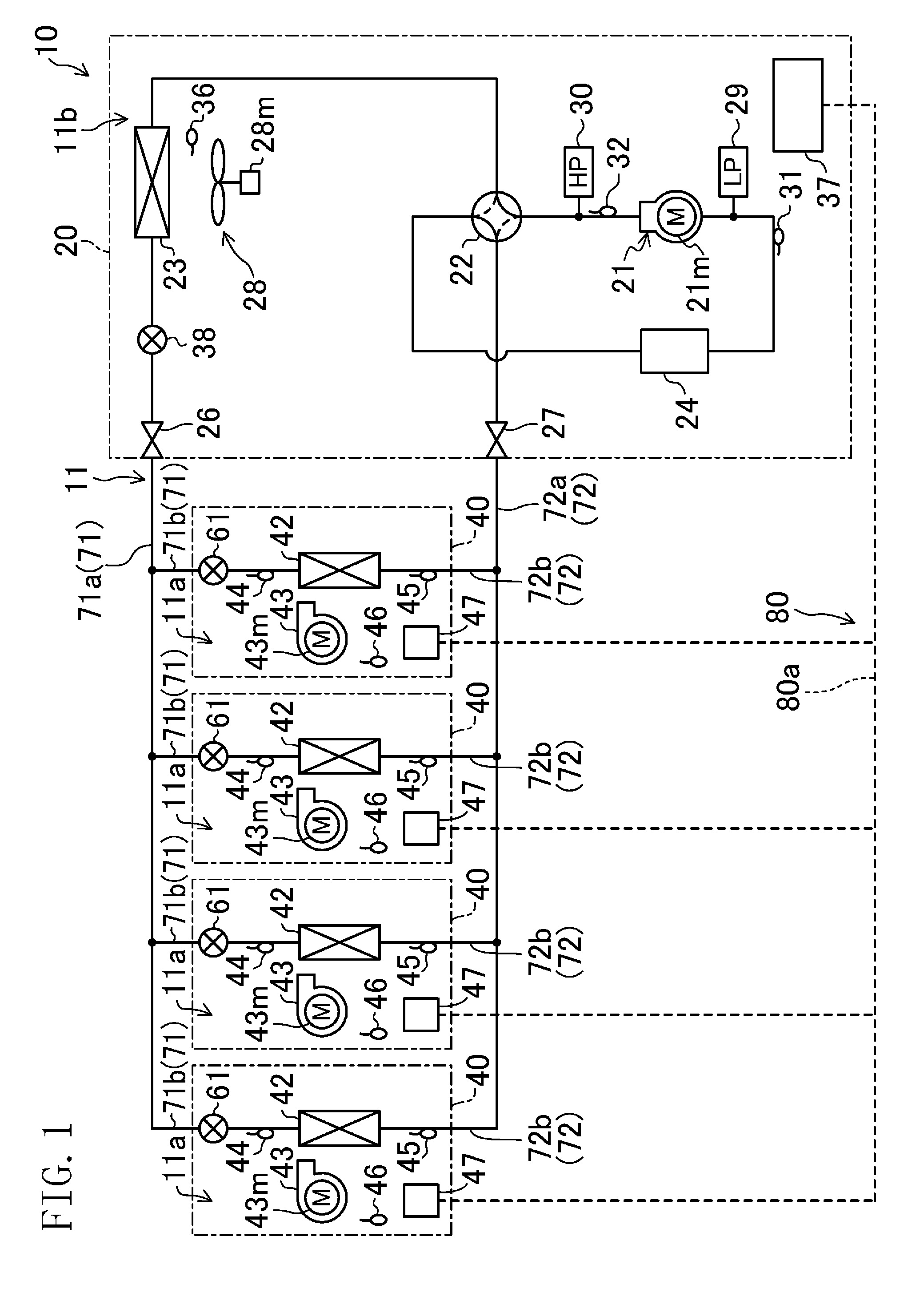
a refrigerant circuit including an outdoor unit and indoor units connected to each other via an interconnecting pipe; and an operation controller controlling operation of the refrigerant circuit, the interconnecting pipe including: a liquid main pipe connected to the outdoor unit, and liquid branch pipes branching off from the liquid main pipe and each connected to a corresponding one of the indoor units; and a gas main pipe connected to the outdoor unit, and gas branch pipes branching off from the gas main pipe and each connected to a corresponding one of the indoor units, the operation controller including an oil collection controller calculating, at predetermined time intervals, an amount of refrigerating machine oil accumulated in the interconnecting pipe during the operation, and integrating the amount calculated for each predetermined time interval, and when a value of the integration exceeds a set amount, performing oil collecting operation for collecting the refrigerating machine oil in the refrigerant circuit into the compressor, wherein the oil collection controller includes an oil accumulation amount calculator (i) determining that, when a flow rate of a gaseous refrigerant in the gas main pipe is determined to be lower than a preset lower limit flow rate in main pipe, the refrigerating machine oil is accumulated in the gas main pipe, and calculating an amount of the refrigerating machine oil accumulated in the gas main pipe as an amount of oil accumulated in main pipe, and (ii) determining that, when the flow rate of the gaseous refrigerant in the gas main pipe is determined to be higher than the preset lower limit flow rate in main pipe and the gas branch pipes are determined to include a gas branch pipe having a flow rate of the gaseous refrigerant higher than a preset lower limit flow rate in branch pipe and a gas branch pipe having a flow rate of the gaseous refrigerant lower than the preset lower limit flow rate in branch pipe, the refrigerating machine oil is accumulated in the gas branch pipe having the flow rate of the gaseous refrigerant lower than the preset set lower limit flow rate in branch pipe, and calculating an amount of the refrigerating machine oil accumulated in the gas branch pipe as an amount of oil accumulated in branch pipe, the oil accumulation amount calculator calculating the integrated value from the amount of oil accumulated in main pipe and the amount of oil accumulated in branch pipe. 2. The air conditioning device of the oil collection controller includes a reference value storage storing, as a reference value for determining the flow rate of the gaseous refrigerant, a refrigerant state value indicating a state of the refrigerant corresponding to the preset lower limit flow rate in branch pipe determined for each of the gas branch pipes, and when calculating the amount of oil accumulated in branch pipe, the oil accumulation amount calculator compares, for each of the gas branch pipes, a current value of the refrigerant state value with the reference value, and calculates the integrated value based on the amount of the refrigerating machine oil accumulated in the gas branch pipe determined to have the flow rate of the gaseous refrigerant lower than the preset set lower limit flow rate in branch pipe. 3. The air conditioning device of the oil collection controller includes a reference value storage storing, as a reference value for determining the flow rate of the gaseous refrigerant, a refrigerant state value indicating, for one or more air volume levels to be set for each of the indoor units, a state of the refrigerant corresponding to the preset lower limit flow rate in branch pipe, and when calculating the amount of oil accumulated in branch pipe, the oil accumulation amount calculator compares the reference value for the one or more air volume levels with a current value of the refrigerant state value of the gas branch pipes for the indoor units, and calculates the integrated value based on the amount of the refrigerating machine oil accumulated in the gas branch pipe determined to have the flow rate of the gaseous refrigerant lower than the preset set lower limit flow rate in branch pipe. 4. The air conditioning device of the reference value storage has the reference value for one or more air volume levels to be set for each of the indoor units, and the oil accumulation amount calculator compares, for each indoor unit, the reference value for the one or more air volume levels with the current value of the refrigerant state value of the gas branch pipes, and calculates the integrated value based on the amount of the refrigerating machine oil accumulated in the gas branch pipe determined to have the flow rate of the gaseous refrigerant lower than the preset set lower limit flow rate in branch pipe. 5. The air conditioning device of the controller performs control in which an evaporation temperature is maintained at a target value in cooling operation, the reference value storage stores a set value of the evaporation temperature as the reference value, and the oil accumulation amount calculator calculates the integrated value based on the amount of the refrigerating machine oil accumulated in a gas branch pipe in which a current value of the evaporation temperature is higher than the set value, the gas branch pipe being included in the gas branch pipes. 6. The air conditioning device of the controller performs control in which a condensing temperature is maintained at a target value in heating operation, the reference value storage stores a set value of the condensing temperature as the reference value, and the oil accumulation amount calculator calculates the integrated value based on the amount of the refrigerating machine oil accumulated in a gas branch pipe in which a current value of the condensing temperature is lower than the set value, the gas branch pipe being included in the gas branch pipes. 7. The air conditioning device of the controller performs control in which an evaporation temperature is maintained at a target value in cooling operation, the reference value storage stores a set value of the evaporation temperature as the reference value, and the oil accumulation amount calculator calculates the integrated value based on the amount of the refrigerating machine oil accumulated in a gas branch pipe in which a current value of the evaporation temperature is higher than the set value, the gas branch pipe being included in the gas branch pipes. 8. The air conditioning device of the controller performs control in which a condensing temperature is maintained at a target value in heating operation, the reference value storage stores a set value of the condensing temperature as the reference value, and the oil accumulation amount calculator calculates the integrated value based on the amount of the refrigerating machine oil accumulated in a gas branch pipe in which a current value of the condensing temperature is lower than the set value, the gas branch pipe being included in the gas branch pipes. 9. The air conditioning device of the controller performs control in which an evaporation temperature is maintained at a target value in cooling operation, the reference value storage stores a set value of the evaporation temperature as the reference value, and the oil accumulation amount calculator calculates the integrated value based on the amount of the refrigerating machine oil accumulated in a gas branch pipe in which a current value of the evaporation temperature is higher than the set value, the gas branch pipe being included in the gas branch pipes. 10. The air conditioning device of the controller performs control in which a condensing temperature is maintained at a target value in heating operation, the reference value storage stores a set value of the condensing temperature as the reference value, and the oil accumulation amount calculator calculates the integrated value based on the amount of the refrigerating machine oil accumulated in a gas branch pipe in which a current value of the condensing temperature is lower than the set value, the gas branch pipe being included in the gas branch pipes.TECHNICAL FIELD
BACKGROUND ART
CITATION LIST
Patent Document
SUMMARY
Technical Problem
Summary
Advantages of the Invention
BRIEF DESCRIPTION OF THE DRAWINGS
DETAILED DESCRIPTION
Operation
Heating Operation
Advantages of Embodiment
Other Embodiments
INDUSTRIAL APPLICABILITY
DESCRIPTION OF REFERENCE CHARACTERS