PHANTOMS AND METHODS AND KITS USING THE SAME
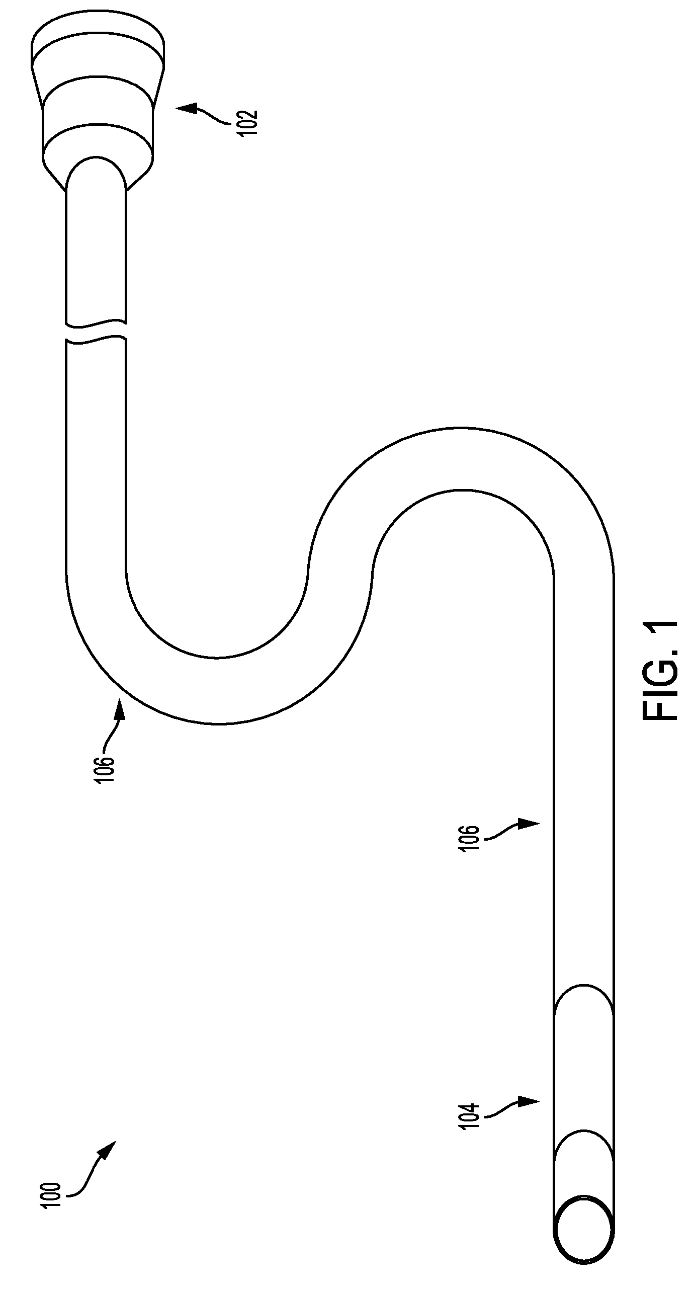
This application claims priority to U.S. Provisional Patent Application Ser. No. 62/152,964, filed Apr. 26, 2015. The entire content of this application is hereby incorporated by reference herein. Phantoms are used to calibrate imaging devices such as X-ray devices. One aspect of the invention provides a phantom including a confined fluidic path defining a plurality of regions of monotonically decreasing, discrete cross-sectional dimensions with respect to an imaging plane. This aspect of the invention can have a variety of embodiments. The phantom can further include one or more marker regions between adjacent regions of monotonically decreasing, discrete cross-sectional dimensions. The one or more marker regions can have a cross-sectional dimension greater than the plurality of regions. The one or more marker regions can have a cross-sectional dimension of about 625 microns. The plurality of regions of monotonically decreasing, discrete cross-sectional dimensions can be defined by tubing of varying internal diameters. The plurality of regions of monotonically decreasing, discrete cross-sectional dimensions can be defined by a monolithic substrate. The phantom can further include an inlet in fluidic communication with the confined fluidic path. The phantom can further include an outlet in fluidic communication with the confined fluidic path. The phantom can be an angiographic phantom. The phantom can be an angiographic X-ray phantom. Another aspect of the invention provides a method of assessing imaging. The method includes: placing a phantom as described herein within an imaging system; flowing one or more fluids through the phantom; and capturing one or more images of the phantom. This aspect of the invention can have a variety of embodiments. The imaging system can be a flat-panel detector (FPD) fluoroscopy system. Another aspect of the invention provides a kit for assessing imaging. The kit includes a phantom as described herein and instructions for use. This aspect of the invention can have a variety of embodiments. The kit can further include a pump having sufficient strength to flow one or more fluids through the phantom. For a fuller understanding of the nature and desired objects of the present invention, reference is made to the following detailed description taken in conjunction with the accompanying drawing figures wherein like reference characters denote corresponding parts throughout the several views. The instant invention is most clearly understood with reference to the following definitions. As used herein, the singular form “a,” “an,” and “the” include plural references unless the context clearly dictates otherwise. Unless specifically stated or obvious from context, as used herein, the term “about” is understood as within a range of normal tolerance in the art, for example within 2 standard deviations of the mean. “About” can be understood as within 10%, 9%, 8%, 7%, 6%, 5%, 4%, 3%, 2%, 1%, 0.5%, 0.1%, 0.05%, or 0.01% of the stated value. Unless otherwise clear from context, all numerical values provided herein are modified by the term about. As used in the specification and claims, the terms “comprises,” “comprising,” “containing,” “having,” and the like can have the meaning ascribed to them in U.S. patent law and can mean “includes,” “including,” and the like. Unless specifically stated or obvious from context, the term “or,” as used herein, is understood to be inclusive. Ranges provided herein are understood to be shorthand for all of the values within the range. For example, a range of 1 to 50 is understood to include any number, combination of numbers, or sub-range from the group consisting 1, 2, 3, 4, 5, 6, 7, 8, 9, 10, 11, 12, 13, 14, 15, 16, 17, 18, 19, 20, 21, 22, 23, 24, 25, 26, 27, 28, 29, 30, 31, 32, 33, 34, 35, 36, 37, 38, 39, 40, 41, 42, 43, 44, 45, 46, 47, 48, 49, or 50 (as well as fractions thereof unless the context clearly dictates otherwise). Embodiments of the invention provide phantoms (e.g., angiographic phantoms) for use in assessing performance of various imaging modalities. Although certain embodiments of the invention are described in the context of fluoroscopy and/or X-ray angiography, embodiments of the invention are applicable to X-ray imaging, magnetic resonance imaging (MM), magnetic resonance angiography (MRA), computed tomography (CT), computed tomography angiography (CTA), fluoroscopy, vascular imaging, ultrasound vascular imaging, conventional angiography (CA), digital subtraction angiography (DSA), non-subtracted angiography, three-dimensional (3D) angiography, and the like. Flat-panel detector (FPD) fluoroscopy systems convert X-rays into a digital electronic signal. The FPD itself consists of over a million detector elements (DEL). The DEL consists of two layers: the first layer, which converts X-rays to light, and the second layer, which converts light to electrical signal. The first layer is called the scintillating layer and includes thallium-activated Cesium Iodide (CsI). The second layer includes a photodiode and a transistor. If light hits the photodiode and transistor layer, the photodiode allows electricity to be conducted; without light, the photodiode prevents the conduction of electricity. The size of the DEL determines the size of the pixel in the image produced by the FPD. For example, pixel size in a detector used for high-resolution vascular imaging is typically 154 microns. Angiography is a medical imaging technique that utilizes a variety of imaging modalities such as X-rays, computed tomography, magnetic resonance, and the like to visualize vessels within the human body. This includes injection of liquid contrast agents such as liquid iodine-containing agents (e.g., OMNIPAQUE® medium available from GE Healthcare of Oslo, Norway) for fluoroscopy and gadolinium-containing contrast agents for magnetic resonance angiography or ultrasound vascular contrast agents that allow for visualization of the vessels. Fluoroscopy systems are utilized by a wide variety of specialists in medicine such as interventional cardiologists, interventional radiologists, interventional neuroradiologists, interventional neurologists, and neurosurgeons. Other types of liquid radiopaque agents used to treat vascular disease processes are also injected under direct visualization using FPD fluoroscopy systems such as agents utilized to treat arteriovenous malformations of the brain, liquid embolic agents, and liquid adhesive agents. Images obtained during contrast injections are post-processed using a digital subtraction (i.e., a mask image is subtracted from a filling image) to display only the filled vascular structure. This Digital Subtraction Angiography (DSA) technique is utilized to visualize vessels in high quality. This process of subtraction allows for visualization of the vasculature solely, without any disturbing background information from bone or soft tissue. During endovascular treatment, a similar process of subtraction is utilized for real time imaging at a lower X-ray dose, a method known as “roadmapping”, where one DSA image with the highest opacification of vessels is superimposed onto a real time fluoroscopy nonsubtracted image, allowing for maneuvering through complex areas of vasculature. During endovascular treatment of cerebrovascular lesions in the central nervous system, liquid embolic agents often must be injected under continuous fluoroscopic visualization to prevent inadvertent migration of these agents into normal vessels of the brain. This is crucial to avoid devastating clinical consequences, especially when working with arteries of the brain. When attempting to visualize arteries of the brain, it is essential to know at what level, i.e. vessel diameter, visualization is being obtained because clinically important perforating cerebral vessels are known to have diameters as small as 120 microns and average in diameters ranging from 330 to 520 microns. Thalamoperforators may arise from the posterior cerebral artery (P1 segment), basilar artery, or superior cerebellar artery and can measure between 100 microns and 1000 microns. Thalamoperforators give off mammillary branches measuring between 120 micron and 370 micron in their outer diameter. Embodiments of the invention provide phantoms, methods, and kits for simulating the flux of a blood arterial tree with continuous tapering that would allow assessment of modern angiographic X-ray machines, specifically their ability to test and objectify the visibility of small cerebral arteries. Such embodiments assess and improve image quality of angiographic systems, and thus increase safety of patients undergoing endovascular treatment procedures. Embodiments of the invention are particularly useful in verifying visualization capabilities at the level of about 100 microns to about 500 microns. Referring now to In one embodiment, a single fluidic path of decreasing cross-sectional dimensions is provided. A single path may be preferred over parallel paths in order to concentrate upstream pressure to propel fluid(s) through narrower downstream regions and minimize the required pressure. Although cylindrical fluid paths are described herein, fluid paths can have a variety of cross-sectional profiles such as rectangles, squares, and the like. In such embodiments, the relevant cross-sectional dimension would be measured in a plane parallel to the table on which the phantom sits (e.g., the bottom surface of the phantom). Proximal end 102 can be coupled to a fluid source in order receive a liquid contrast agent. For example, the proximal end 102 can include a female Luer taper. In another example, the proximal end 102 is coupled to a motor and/or pump (e.g., a peristaltic pump) to inject a radiopaque substance. The motor and/or pump can be controllable to inject a controlled amount (e.g., by volumetric velocity and the like) of a liquid contrast agent. Markers 110 can be gaps having a sufficiently large cross-section so as to be clearly visualized in any situation and provide confirmation that the liquid contrast agent flowed through an upstream section that have a narrower cross-section. For example, markers 110 can have a cross-sectional dimension greater than the cross-sectional dimensional of a largest region 108 In In Referring now to The phantoms described herein can be fabricated from a variety of materials. In some embodiments, the phantom is includes a plurality of tubing sections. In other embodiments, the phantom includes a solid structure defining passages of varying diameter. Phantoms are preferably fabricated from an X-ray, magnetic field, and/or radio wave transparent material. Additionally, the phantoms are preferably fabricated from a dimethyl sulfoxide (DMSO)-compatible material. Suitable materials include polymers such as LDPE, HDPE, polypropylene (PP), polypropylene copolymer (PPCO), polymethylpentene, nylon, polytetrafluoroethylene (PTFE) (e.g., TEFLON® available from The Chemours Company of Wilmington, Del.), fluorinated ethylene propylene (FEP), and the like. Other suitable materials include glass, silicon, polyetheretherketone (PEEK), other radiolucent plastics, ex vivo specimens from cadavers, and the like. Phantoms can be fabricated using a variety of techniques including casting, molding, machining, thermomolding, thermosetting, injection molding, vacuum forming, additive manufacturing (also known as 3D printing), and the like. The phantoms and methods described herein can be utilized to assess visualization of a variety of liquid contrast agents or other contrast-containing therapeutic agents such as radiopaque iodine-containing fluids, gadolinium-containing agents, MR contrast agents, ultrasound vascular contrast agents, adhesive and non-adhesive liquid embolic agents (e.g., ONYX® available from ev3 Endovascular, Inc. of Plymouth, Minn.), acrylic glues, any substance injected under visualization during angiography, and the like. The phantoms and methods described herein can be utilized to compare visualization of a variety of liquid contrast agents to other contrast-containing therapeutic agents. The phantoms and methods described herein can be utilized to calibrate imaging devices to promote optimal imaging (e.g., of vessels having a diameter between about 120 microns and about 330 microns). The phantoms and methods described herein can also be utilized to compare visualization of liquid contrast agents across varying imaging devices. Referring now to Referring now to Although preferred embodiments of the invention have been described using specific terms, such description is for illustrative purposes only, and it is to be understood that changes and variations may be made without departing from the spirit or scope of the following claims. The entire contents of all patents, published patent applications, and other references cited herein are hereby expressly incorporated herein in their entireties by reference. One aspect of the invention provides a phantom including a confined fluidic path defining a plurality of regions of monotonically decreasing, discrete cross-sectional dimensions with respect to an imaging plane. Another aspect of the invention provides a method of assessing imaging. The method includes: placing a phantom as described herein within an imaging system; flowing one or more fluids through the phantom; and capturing one or more images of the phantom. Another aspect of the invention provides a kit for assessing imaging. The kit includes a phantom as described herein and instructions for use. 1. A phantom comprising:
a confined fluidic path defining a plurality of regions of monotonically decreasing, discrete cross-sectional dimensions with respect to an imaging plane. 2. The phantom of one or more marker regions between adjacent regions of monotonically decreasing, discrete cross-sectional dimensions. 3. The phantom of 4. The phantom of 5. The phantom of 6. The phantom of 7. The phantom of an inlet in fluidic communication with the confined fluidic path. 8. The phantom of an outlet in fluidic communication with the confined fluidic path. 9. The phantom of 10. The phantom of 11. A method of assessing imaging, the method comprising:
placing the phantom of flowing one or more fluids through the phantom; and capturing one or more images of the phantom. 12. The method of 13. A kit for assessing imaging, the kit comprising:
the phantom of instructions for use. 14. The kit of a pump having sufficient strength to flow one or more fluids through the phantom. 15. A phantom comprising:
an inlet; an outlet; and a single confined fluidic path in fluidic communication with the inlet and the outlet, the single confined fluidic path comprising:
a plurality of regions of monotonically decreasing, discrete internal cross-sectional dimensions with respect to an imaging plane; and one or more marker regions between adjacent regions of monotonically decreasing, discrete internal cross-sectional dimensions, the one or more marker regions having an internal cross-sectional dimension greater than any of the plurality of regions. 16. The phantom of 17. The phantom of 18. The phantom of 19. The phantom of CROSS-REFERENCE TO RELATED APPLICATION
BACKGROUND OF THE INVENTION
SUMMARY OF THE INVENTION
BRIEF DESCRIPTION OF THE DRAWINGS
DEFINITIONS
DETAILED DESCRIPTION OF THE INVENTION
Flat-Panel Detector (FPD) Fluoroscopy Systems
Angiography
Phantoms
Sample Materials
Sample Liquid Contrast Agents
Calibration and Comparison of Imaging Systems
WORKING EXAMPLES
EQUIVALENTS
INCORPORATION BY REFERENCE