ENDOSCOPE CONNECTOR
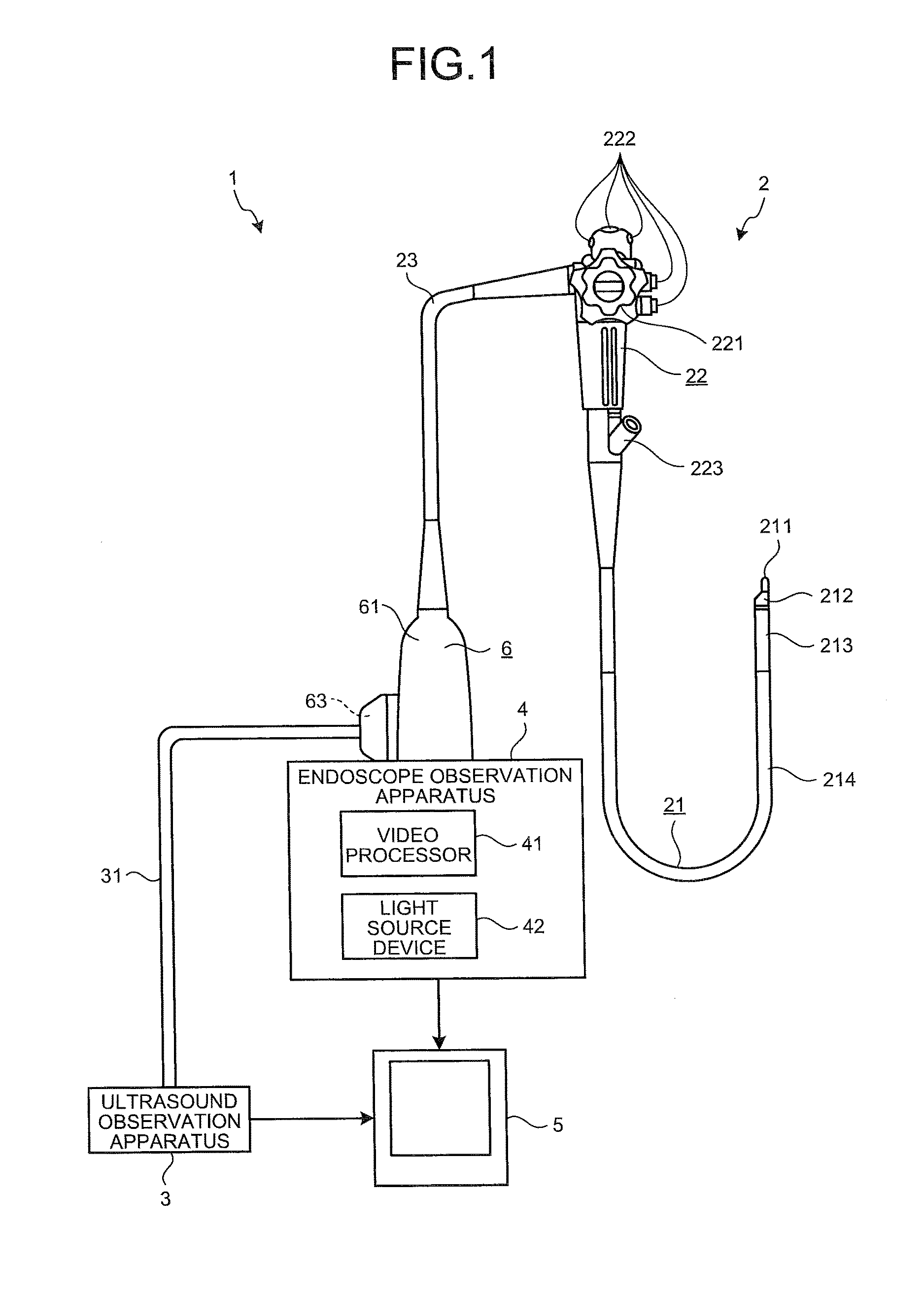
This application is a continuation of PCT international application Ser. No. PCT/JP2016/061806 filed on Apr. 12, 2016 which designates the United States, incorporated herein by reference, and which claims the benefit of priority from Japanese Patent Applications No. 2015-170676, filed on Aug. 31, 2015, incorporated herein by reference. The present disclosure relates to an endoscope connector. In the related art, there has been known an endoscope system in which an ultrasound endoscope including an insertion portion to be inserted into a subject, an ultrasound observation apparatus that processes a signal from an ultrasound transducer provided at a distal end of the insertion portion, and an endoscope observation apparatus that processes a signal from an image sensor provided at the distal end of the insertion portion are connected via an endoscope connector (for example, refer to JP 2007-185392 A). The endoscope connector (connector portion) described in JP 2007-185392 A includes an outer casing having an attachment hole, and an ultrasound connector attached to the attachment hole. In addition, a first metal member (connector portion main body) being a metal connected to a patient GND on the endoscope observation apparatus side, and a second metal member (metal member) being a grounding GND metal on the ultrasound observation apparatus side that is attached to the ultrasound connector are provided in the outer casing. In addition, the first and second metal members are electrically-isolated from each other, and electrically connected via a capacitor in a high-frequency manner, for causing an ultrasound image generated by the ultrasound observation apparatus, to be a good image with reduced noise, and assuring electrical safety. An endoscope connector according to one aspect of the present disclosure includes: an outer casing including an attachment hole configured to communicate between an inside and an outside of the outer casing; an electrical connector attached to the attachment hole; a first metal member disposed in the outer casing; a second metal member attached to the electrical connector; an insulating member placed between the first metal member and the second metal member in a state in which the electrical connector is attached to the attachment hole, the insulating member electrically insulating the first metal member and the second metal member from each other; a capacitor fixed to the insulating member; a first conduction member fixed to the insulating member and electrically connected to one leg of the capacitor, the first conduction member contacting the first metal member to be electrically connected to the first metal member in the state in which the electrical connector is attached to the attachment hole; and a second conduction member fixed to the insulating member and electrically connected to another leg of the capacitor, the second conduction member contacting the second metal member to be electrically connected to the second metal member in the state in which the electrical connector is attached to the attachment hole. The above and other objects, features, advantages and technical and industrial significance of this disclosure will be better understood by reading the following detailed description of presently preferred embodiments of the disclosure, when considered in connection with the accompanying drawings. A mode for carrying out the present disclosure (hereinafter, referred to as an embodiment) will be described below with reference to the drawings. In addition, the present disclosure is not limited by the embodiment to be described below. Furthermore, in the description of the drawings, the same parts are assigned the same signs. The endoscope system 1 is a system for performing ultrasound diagnosis of the inside of a subject such as a human, using an ultrasound endoscope. As illustrated in Part of the endoscope 2 may be inserted into a subject, and the endoscope 2 is an ultrasound endoscope having a function of transmitting an ultrasound pulse toward a body wall on the inside of the subject, receiving an ultrasound echo reflected by the subject, and outputting an echo signal, and a function of imaging the inside of the subject to output an image signal. In addition, a detailed configuration of the endoscope 2 will be described later. The ultrasound observation apparatus 3 electrically-connects to the endoscope 2 via an ultrasound cable 31 ( An endoscope connector 6 (refer to The video processor 41 outputs a control signal to the endoscope 2 via the endoscope connector 6, and inputs an image signal from the endoscope 2 via the endoscope connector 6. Then, the video processor 41 performs predetermined processing on the image signal to generate an endoscope image. The light source device 42 supplies, via the endoscope connector 6, the endoscope 2 with illumination light for illuminating the inside of the subject. The display device 5 is formed by using a liquid crystal or an organic electro luminescence (EL), and displays the ultrasound image generated in the ultrasound observation apparatus 3, the endoscope image generated in the endoscope observation apparatus 4, and the like. As illustrated in Here, a light guide for transmitting illumination light supplied from the light source device 42, a US cable for ultrasound observation (for the transmission of a pulse signal and an echo signal), an imaging cable C1 (refer to The insertion portion 21 is a portion to be inserted into the subject. As illustrated in Here, in addition to the aforementioned light guide, the US cable, and the imaging cable C1 (refer to In the example illustrated in Here, the ultrasound transducer includes an acoustic lens, a piezoelectric element, and a matching layer, and acquires an ultrasound echo contributing to an ultrasound tomographic image of the inside of the body wall on the inside of the subject. Then, the ultrasound probe 211 converts a pulse signal input from the ultrasound observation apparatus 3 via the aforementioned US cable and the ultrasound cable 31, into an ultrasound pulse, and transmits the ultrasound pulse into the subject. In addition, the ultrasound probe 211 converts an ultrasound echo reflected inside the subject, into an electrical echo signal, and outputs the electrical echo signal to the ultrasound observation apparatus 3 via the above-described US cable and the ultrasound cable 31. The rigid member 212 is a hard member formed of resin material, and has a substantially-circular cylindrical shape. Here, an observation window, an illumination window, a processing tool passage, and the like are formed in the rigid member 212, though these are not specifically illustrated in the drawing. The observation window, the illumination window, and the processing tool passage are holes penetrating through from the proximal end (end portion on the operating unit 22 side) of the rigid member 212 toward a distal end, and more specifically, have the following functions. The observation window is a hole for acquiring an optical image of the inside of the subject. In addition, an image sensor (not illustrated) that is connected to the aforementioned imaging cable C1 (refer to The illumination window is a hole for emitting illumination light into the subject. In addition, an emission end side of the aforementioned light guide is inserted into the illumination window. The processing tool passage is a hole for causing the various processing tools to protrude outward. In addition, the aforementioned processing tool tube is connected to the processing tool passage. The operating unit 22 is a portion that is connected to a proximal end side of the insertion portion 21, and receives various operations from a doctor or the like. As illustrated in In addition, a processing tool insertion port 223 that is communicated with the aforementioned processing tool tube, and is provided for inserting the various processing tools into the processing tool tube is formed in the operating unit 22. Here, in the operating unit 22, the imaging cable C1 ( As illustrated in One end of the first imaging cable C11 is electrically connected to the aforementioned image sensor, and the other end thereof is electrically connected to a relay board Rb provided in the operating unit 22 while repeating meandering a plurality of times. In addition, the first imaging cable C11 performs transmission of an image signal and a control signal between the aforementioned image sensor and the relay board Rb. In addition, the relay board Rb is illustrated using a dashed-dotted line in One end of the second imaging cable C12 is electrically connected to the relay board Rb, and the other end thereof is electrically connected to a first circuit board Cb1 (refer to As illustrated in In other words, the respective shields of the first and second imaging cables C11 and C12 are ensured at the same electric potential, and connected to the same electric potential as the patient GND. The universal cable 23 is a cable having one end connected to the operating unit 22, and is a cable in which a remote switch cable for transmitting an operation signal according to various operations performed on the operating unit 22 (e.g., operations for instructing freeze, release, and edge enhancement of an endoscope image, an operation for instructing light adjustment of the light source device 42, etc.) is laid in addition to the aforementioned light guide, the US cable, and the imaging cable (the second imaging cable C12). The endoscope connector 6 is provided at the other end of the universal cable 23, and is a connector for connecting to the ultrasound cable 31 connected to the ultrasound observation apparatus 3, and the endoscope observation apparatus 4 (the video processor 41 and the light source device 42). Next, a configuration of the endoscope connector 6 will be described. In the following description, based on a posture of when the endoscope connector 6 is connected to the endoscope observation apparatus 4, an upper side in the posture is regarded as “up”, a downside in the posture is regarded as “down”, a side approaching the endoscope observation apparatus 4 is regarded as “front”, a side separated from the endoscope observation apparatus 4 is regarded as “rear”, a left side viewed from a front side in the posture is regarded as “left”, and a right side viewed from the front side in the posture is regarded as “right”. In addition, in As illustrated in As illustrated in As illustrated in The protruding portion 612 is communicated with the inside of the outer casing 61, and has a hollow shape. In addition, as illustrated in Here, as illustrated in The first and second circuit boards Cb1 and Cb2 are supported by the first metal member 64 in the outer casing 61, in a posture substantially-parallel to an XY plane, and in a posture in which they face each other in the Z-axis direction. In addition, in As illustrated in As illustrated in Then, as illustrated in In other words, the US cable C2 is laid at a position separated from a location where noise is easily generated from the first circuit board Cb1 electrically connected at a position closest to the endoscope observation apparatus 4 when the first and second circuit boards Cb1 and Cb2 are compared, that is, at a position separated from the first circuit board Cb1. Thus, the influence of noise exerted on the US cable C2 may be suppressed, and an ultrasound image may be a good image with a reduced noise. In the US cable C2, the aforementioned meandering portion, that is, a portion bent at an angle equal to or smaller than at least 90° is coated with a heat shrinkable tube in a not-shrunk state, for preventing damages to the portion. In addition, in the US cable C2, if there is a portion bent at an angle equal to or smaller than at least 90°, such as, for example, a portion laid from the inside of the operating unit 22 to the inside of the universal cable 23, aside from the inside of the outer casing 61, the portion may be similarly coated with a heat shrinkable tube in a not-shrunk state. Here, as illustrated in In other words, the fixing pin Pi may prevent mechanical interference between the flexible board Fp and the US cable C2, and prevent the flexible board Fp from being removed from the FPC connector mounted on the second circuit board Cb2. The shield casing Sh2 is a shield member having a substantially-cylindrical shape following the inner surface of the outer casing 61. In addition, as illustrated in In other words, the shield casing Sh2 is connected to the same electric potential as the patient GND on the endoscope observation apparatus 4 side, and reduces radiation noise generated from the first and second circuit boards Cb1 and Cb2. The plug portion 62 is a portion to be inserted into the endoscope observation apparatus 4, and connected to the video processor 41 and the light source device 42, and is attached to an aperture portion on the front side of the outer casing 61 as illustrated in As illustrated in In the first electrical connector portion 621, on part of the outer circumferential surface, a plurality of first electrical contact points 621A is provided in a circumferential direction. As illustrated in In the second electrical connector portion 622, on part of the outer circumferential surface, a plurality of second electrical connector portions 622A is provided in the circumferential direction. As mentioned above, the above-described plurality of first and second electrical contact points 621A and 622A are electrically connected to the imaging cable C1 and the aforementioned remote switch cable via the signal cable C3 and the first and second circuit boards Cb1 and Cb2. In addition, the plurality of first and second electrical contact points 621A and 622A are electrically connected to the video processor 41 in a state in which the plug portion 62 is inserted into the endoscope observation apparatus 4. In other words, the plurality of first and second electrical contact points 621A and 622A are portions electrically-connecting the imaging cable C1 and the aforementioned remote switch cable, and the video processor 41. The light guide cap 623 is attached to an end surface on the front side of the second electrical connector portion 622, and protrudes from the end surface on the front side in the +Y-axis direction. In addition, an incidence end side of the aforementioned light guide is inserted into the light guide cap 623. In addition, the light guide cap 623 connects to the light source device 42 in a state in which the plug portion 62 is inserted into the endoscope observation apparatus 4. In other words, the light guide cap 623 is a portion optically-connecting the aforementioned light guide and the light source device 42. The ultrasound connector 63 is an electrical connector for electrically-connecting the US cable C2 and the ultrasound cable 31. As illustrated in The ultrasound board 631 has a substantially-circular disc shape, and is a board having a surface (surface on the outer casing 61 inner side) on which a plurality of (12 in the present embodiment) FPC connectors 6311 ( As illustrated in The plurality of pin terminals 6312 are arrayed in a matrix in a substantially-center portion of the ultrasound board 631. In addition, the plurality of pin terminals 6312 are electrically connected to the US cable C2 via the FPC connectors 6311 and the aforementioned plurality of flexible boards, and electrically connected to the ultrasound cable 31 when the ultrasound cable 31 is connected to the ultrasound connector 63. As illustrated in As illustrated in In addition, one end side of the US cable C2 is fixed to the portion 6331 on one end side of the L-shaped cross-section in the electrical connection member 633. As illustrated in As partially illustrated in As illustrated in In addition, the aforementioned frame member 632, the electrical connection member 633, the spacer 634, and the second metal member 65 are connected to the same electric potential as a grounding GND on the ultrasound observation apparatus 3 side via the ultrasound cable 31. As illustrated in The insulating member 66 is a member formed of insulating material, and electrically-insulating the first and second metal members 64 and 65 from each other. In addition, as illustrated in As illustrated in As illustrated in The storage portion 6611 is formed on a lateral surface (surface on the outer casing 61 inner side) of the bottom portion of the insulating member main body 661. As illustrated in In addition, as illustrated in In addition, the first and second wall portions 6611A and 6611B are formed to extend in the same direction as the portion 6331 on one end side of the L-shaped cross-section in the electrical connection member 633, in a state in which the insulating member main body 661 is fixed to the frame member 632. As illustrated in In addition, as illustrated in As illustrated in Then, as illustrated in In addition, in a state in which the insulating member main body 661 is fixed to the frame member 632, the second finger 69 contacts the second metal member 65 to be electrically connected to the second metal member 65. In addition, in a state in which the ultrasound connector 63 is attached to the attachment hole 612A, the first finger 68 contacts the first metal member 64 to be electrically connected to the first metal member 64. In other words, the first and second metal members 64 and 65 are electrically connected via the capacitor 67 in a high-frequency manner. The above-described insulating member main body 661 covers one leg 671 of the capacitor 67 and the first finger 68 when viewed from the ultrasound connector 63 side ( In addition, almost the entire insulating member main body 661 is formed so as to have a thickness of 0.4 mm or more. As illustrated in The protection member 662 is a member for protecting one end side of the US cable C2 that is inserted into the insulating member main body 661 and the second metal member 65 through the cutout portions 6614 and 651. As illustrated in In the endoscope connector 6 according to the above-described present embodiment, the first and second metal members 64 and 65 are electrically insulated from each other by interposing the insulating member 66 between the first and second metal members 64 and 65. In addition, by fixing the capacitor 67 and the first and second fingers 68 and 69 to the insulating member 66, when the ultrasound connector 63 is attached to the attachment hole 612A, the first and second metal members 64 and 65 are electrically connected via the capacitor 67 in a high-frequency manner. Thus, the endoscope connector 6 according to the present embodiment brings about such an effect that the first and second metal members 64 and 65 may be electrically connected via the capacitor 67 in a high-frequency manner only by attaching the ultrasound connector 63 to the attachment hole 612A, and assembling workability may be enhanced. In addition, in the endoscope connector 6 according to the present embodiment, the first and second fingers 68 and 69 are employed as the first and second conduction members according to the present disclosure. Thus, the legs 671 and 672 of the capacitor 67 and the first and second metal members 64 and 65 may be electrically connected with certainty using a simple configuration. In addition, in the endoscope connector 6 according to the present embodiment, the insulating member main body 661 functioning as the coating portion according to the present disclosure is set to have the entire thickness of 0.4 mm or more. Thus, the first and second metal members 64 and 65 may be electrically insulated from each other with certainty. In addition, in the endoscope connector 6 according to the present embodiment, the insulating member main body 661 is formed in a container shape in which part of the ultrasound connector 63 is accommodated. Thus, only by fixing the insulating member main body 661 to the frame member 632, the other leg 672 (second finger 69) of the capacitor 67 and the second metal member 65 may be electrically connected. Thus, assembling workability of the endoscope connector 6 may be further enhanced. A mode for carrying other the present disclosure has been described so far. Nevertheless, the present disclosure is not to be limited only by the aforementioned embodiment. In the aforementioned embodiment, the endoscope system 1 has both of a function for generating an ultrasound image, and a function for generating an endoscope image. Nevertheless, the endoscope system 1 is not limited to this configuration, and the endoscope system 1 may have a configuration only having either one of the functions. In the aforementioned embodiment, the insulating member main body 661 is formed in a container shape. Nevertheless, the insulating member main body 661 is not limited to this configuration, and may have a configuration only including a bottom portion by omitting a side surface portion of the insulating member main body 661, for example, as long as the first and second metal members 64 and 65 may be electrically insulated from each other. In addition, the storage portion 6611 is formed on the lateral surface of the bottom portion of the insulating member main body 661. Nevertheless, the storage portion 6611 is not limited to this configuration, and may have a configuration formed on the medial surface of the bottom portion of the insulating member main body 661. In the aforementioned embodiment, only one capacitor 67 is provided. Nevertheless, the number of capacitors 67 is not limited to this. As another configuration, two or more capacitors 67 may be provided as long as the capacitors 67 are connected in parallel. In the aforementioned embodiment, the endoscope system 1 is not limited to the medical field, and may be used in the industrial field, and used as an endoscope system that observes the inside of a subject such as a machine structure. In the endoscope connector according to the present disclosure, the first and second metal members are electrically insulated from each other by interposing the insulating member between the first and second metal members. In addition, by fixing the capacitor and the first and second conduction members to the insulating member, when the electrical connector is attached to the attachment hole, the first and second metal members are electrically connected via the capacitor in a high-frequency manner. Thus, the endoscope connector according to the present disclosure brings about such an effect that the first and second metal members may be electrically connected via the capacitor in a high-frequency manner only by attaching the electrical connector to the attachment hole, and assembling workability may be enhanced. Additional advantages and modifications will readily occur to those skilled in the art. Therefore, the disclosure in its broader aspects is not limited to the specific details and representative embodiments shown and described herein. Accordingly, various modifications may be made without departing from the spirit or scope of the general inventive concept as defined by the appended claims and their equivalents. An endoscope connector includes: an outer casing including an attachment hole configured to communicate between an inside and an outside of the outer casing; an electrical connector attached to the attachment hole; a first metal member disposed in the outer casing; a second metal member attached to the electrical connector; an insulating member placed between the first metal member and the second metal member, the insulating member electrically insulating the first metal member and the second metal member from each other; a capacitor fixed to the insulating member; a first conduction member fixed to the insulating member and electrically connected to one leg of the capacitor to be electrically connected to the first metal member; and a second conduction member fixed to the insulating member and electrically connected to another leg of the capacitor to be electrically connected to the second metal member. 1. An endoscope connector comprising:
an outer casing including an attachment hole configured to communicate between an inside and an outside of the outer casing; an electrical connector attached to the attachment hole; a first metal member disposed in the outer casing; a second metal member attached to the electrical connector; an insulating member placed between the first metal member and the second metal member in a state in which the electrical connector is attached to the attachment hole, the insulating member electrically insulating the first metal member and the second metal member from each other; a capacitor fixed to the insulating member; a first conduction member fixed to the insulating member and electrically connected to one leg of the capacitor, the first conduction member contacting the first metal member to be electrically connected to the first metal member in the state in which the electrical connector is attached to the attachment hole; and a second conduction member fixed to the insulating member and electrically connected to another leg of the capacitor, the second conduction member contacting the second metal member to be electrically connected to the second metal member in the state in which the electrical connector is attached to the attachment hole. 2. The endoscope connector according to 3. The endoscope connector according to 4. The endoscope connector according to 5. The endoscope connector according to 6. The endoscope connector according to wherein the insulating member is formed in a container shape in which part of the electrical connector is accommodated, and the second conduction member contacts the second metal member fixed to the electrical connector and is electrically connected to the second metal member in a state in which the part of the electrical connector is accommodated in the insulating member. 7. The endoscope connector according to wherein the first metal member is connected to an electric potential that is same as a patient GND of an endoscope observation apparatus, and the second metal member is connected to a grounding GND of a ultrasound observation apparatus.CROSS-REFERENCE TO RELATED APPLICATIONS
BACKGROUND
SUMMARY
BRIEF DESCRIPTION OF THE DRAWINGS
DETAILED DESCRIPTION
Schematic Configuration of Endoscope System
Configuration of Endoscope
Configuration of Endoscope Connector
Other Embodiments