Curved crease honeycombs with tailorable stiffness and dynamic properties
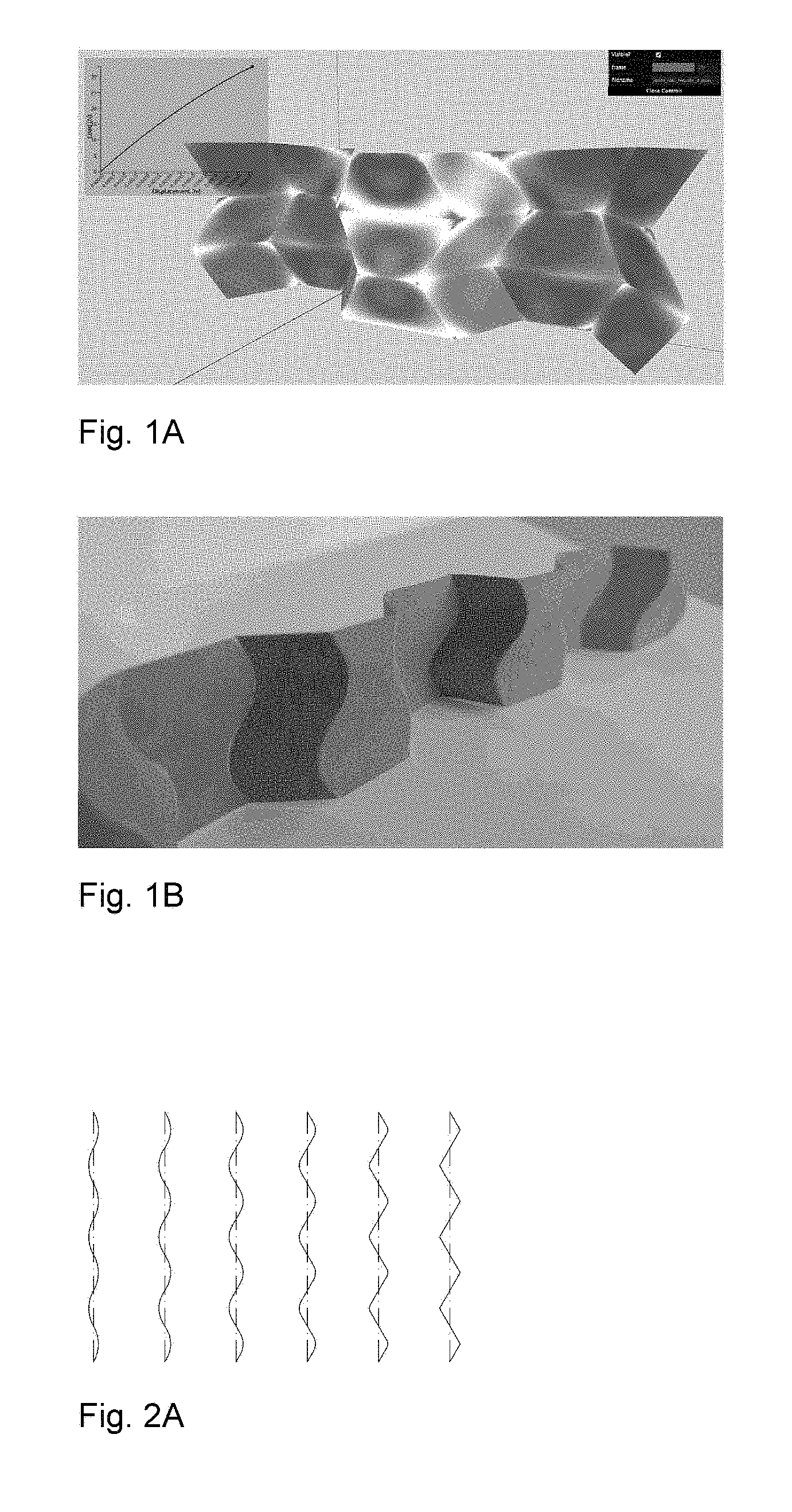
This application is related to, and claims priority from U.S. Provisional Patent Application No. 62/476,496 filed Mar. 24, 2017. Application No. 62/476,496 is hereby incorporated by reference in its entirety. The present invention relates generally to pleat walled honeycomb structures used to provide tunable light-weight structurally strong members and more particularly to a class of curved crease honeycombs. Application PCT/US2016/068765 shows methods to produce “pleat-walled” honeycombs with tailorable stiffness by adjusting a parameter of a two-dimensional folding pattern. In particular, by changing a pleat angle, the effective stiffness of the resulting honeycomb can be made to take on a range of values. When compressing pleat-walled honeycombs to large strains, significant stress concentrations can appear at the pleat vertices. The present invention provides a solution to the three aforementioned issues with pleat walled honeycombs by replacing the polygonal creases with curved creases. In Second, the curved creases also serve to give better control over material properties. With pleated-wall honeycombs, the pleat angle alone determines the geometry, and hence the in-plane stiffness of the structure. With curved crease honeycombs, there are additional degrees of freedom in how the curve is parameterized. This is described in detail in “Parameterizations”. Besides just having additional degrees of design freedom, curved crease honeycombs exhibit two phenomena not present in pleat-walled honeycombs: 1) facet bending, 2) blocked states. Because facets bend, this can be used to store elastic energy, providing a more reliable source of stiffness than the hinge stiffness alone. The blocked states of curved crease honeycombs allow tailoring of the large deformation behavior of the honeycomb. For instance, one can specify a desired initial stiffness which then increases after a prescribed amount of strain. This is described in detail in “Material Properties”. Third, the curved crease honeycombs do not require any of the horizontally-running creases seen in With these advantages of the present invention over pleat-walled honeycombs, many of their advantages can still be applied. For instance, by controlling the location of cuts and folds in two-dimensions, the three-dimensional shape can be specified. This eliminates the need for external molds or post-machining in a number of applications, and allows for great manufacturing flexibility, on-demand production, and lower overall cost and energy inputs. Attention is not directed to several figures that illustrate features of the present invention. Several drawings and illustrations have been presented to aid in understanding the present invention. The scope of the present invention is not limited to what is depicted in the figures. In generalizing from pleated-wall honeycombs to curved crease honeycombs, one must choose which curves to use for the creases. While nearly any periodic curve will work (e.g. a sine function); the preferred primarily parameterizations of the present invention are biarc and elastica curves. Biarcs are piecewise-defined alternating lines and arcs such that consecutive sections are mutually tangent. Several examples are shown in To calculate the geometry arising from this biarc parameterization, it is first noted that for period 2 π and pleat angle α, the amplitude a corresponding to a curve with zero arc fraction is (π/2)/tan(α). These transition coordinates can be used to define a piecewise function for the biarc curve. For instance, the arc segment is given by Using these expressions, one can calculate the geometry of biarc-based curved crease honeycombs. In The second crease curve parameterization used is given by elastica curves, or the shape made by an elastic beam subject to an end load. The advantage to this parameterization is that the curved creases enforce a shape very similar to the natural shape of the bent facets under compressive loading. This lowers the stress seen by the crease and extends its lifetime. Timoshenko (Theory of Elastic Stability, pp 76-) shows how to derive expressions for total deflection of the beam ends using elliptic integrals. The full shapes can be calculated in closed form using incomplete elliptic integrals, or we can use numerical integration of the governing differential equation: Where E is the material elastic modulus, I is the second area moment of inertia, s is the length measured along the beam, P is a force, and θ is the angle made by the beam with respect to the vertical. This equation is simply a statement that bending moment equals flexural rigidity times the curvature. This formulation can also be parameterized by effective pleat angle α made by the crease line at its end with respect to the vertical with the substitution Where K denotes the complete elliptic integral of the first kind and l denotes the length of the beam. The parameterizations described above can be used to tailor the material properties of the resulting curved crease honeycombs. The initial stiffness (stiffness at low strains) is largely a dependent on the relationship between height of the honeycomb and the bending of its facets. The flexural rigidity of each facet resists this bending, and hence the honeycomb itself becomes a spring. More specifically, the force exerted by the honeycomb in the direction of compression (z) is equal to minus the derivative of stored elastic energy with respect to z. This elastic energy for each facet is proportional to the integral over the facet of curvature squared. The facet curvature is a direct function of crease curvature and fold angle. Hence, the stiffness of the honeycomb is a function not only of the value of curvature of the crease, but the distribution of curvature over the crease. Hence, stiffness can be controlled by tuning this parameters. Secondary stiffness (stiffness at large strains) can be controlled by utilizing the curved crease honeycomb's blocked state, that is, the state after which no further folding mechanism is possible due to geometric constraints. In These tunable properties of curved crease honeycombs can be used to set dynamic, as well as static properties. Conversely, curved crease honeycombs can also be made to return energy efficiently upon compaction. Due to the reduced number of creases as compared to pleated-wall honeycombs, curved crease honeycombs can be manufactured more efficiently. Three methods are discribed, though many other are possible. First a method inspired by the “expansion” fabrication of straight-walled honeycombs is shown where many flat sheets are selectively glued or welded along evenly spaced lines with parity that alternates with each sheet. When the sheets are pulled apart (i.e., expanded), the honeycomb creases are formed as the sheet material is pulled taut between the bond lines. A similar method can be used with curved crease honeycombs, where instead of straight bond lines, the bonding is along the curved crease lines. When expanded, the curved creases are actuated in parallel, effectively folding many at once. This method works well if crease curvature is relatively small, but larger curvature is problematic due to the bistable singularity of the curved crease in its flat state. For larger crease curvature, however, one can modify the above expansion fabrication method as shown in Second, a manufacturing method inspired by the method of fabricating straight-walled honeycombs is shown consisting of corrugating, stacking, and selectively bonding sheets. Instead of corrugating, however, a steel rule die is used, which creases sheets when used to press them into an elastomer substrate and can accommodate a variety of curved crease shapes. These creased sheets are then stacked and bonded to form a honeycomb. A version of this method is shown in Third, a manufacturing method amenable to composite materials like carbon fiber reinforced polymer is shown. While this method was specifically developed for composite materials, it also works with metal, polymer, or other more conventional base materials. In this method, we use an oscillating knife to cut a stack of pre-impregnated fiber, arranged according to a prescribed layup schedule. In Several descriptions and illustrations have been presented to aid in understanding the present invention. One with skill in the art will realize that numerous changes and variations may be made maintaining the spirit of the invention and are within the scope of the present invention. Issues with pleat walled honeycombs are solved by replacing polygonal creases with curved creases. As with a conventional straight-walled honeycomb, these strips can be combined into a space-filling honeycomb structure. The benefits of these curved creases are threefold. First, the stress concentrations mentioned above with pleat-walled honeycombs are mitigated. The stress due to finite material thickness is spread more evenly over the crease line, instead of being concentrated at a point, as with pleat walled honeycombs. As a result, the maximal value observed is lower and the adverse effects are reduced. Second, the curved creases also serve to give better control over material properties, and third, the curved crease honeycombs do not require any of the horizontally-running creases. The curves are typically mathematical curves that can be computed algebraically or by solving a differential equation. 1. A honeycomb structure comprising:
a plurality of 3-dimensional structural honeycombs formed from a cut and folded substrate sheet that has a regular pattern of cut areas and creases, each of said creases being a curved crease following a predefined mathematical curve, the plurality of honeycombs each having identical cells; each cell having at least one pleat angle, and each cell having at least one face abutting at least one face of another cell; at least one join between some abutting faces of the structure that stabilizes the structure into a fixed shape. 2. The honeycomb structure of 3. The honeycomb structure of and x and y coordinates of a transition from line segment to arc are defined by
and an arc segment is defined by:
4. The honeycomb structure of 5. The honeycomb structure of where K is a complete elliptic integral of the first kind, l is a beam length, E is the material elastic modulus, I is the second area moment of inertia, and P is a force. 6. The honeycomb structure of 7. The honeycomb structure of where E is the material elastic modulus, I is the second area moment of inertia, s is the length measured along a beam, P is a force, and θ is the angle made by the beam with respect to the vertical. 8. The honeycomb structure of 9. The honeycomb structure of 10. The honeycomb structure of 11. The honeycomb structure of 12. A honeycomb structure comprising a plurality of 3-dimensional honeycombs, wherein each of said honeycombs has at least one curved crease. 13. The honeycomb structure of 14. The honeycomb structure of 15. The honeycomb structure of 16. A method of fabricating a curved crease honeycomb structure comprising:
gluing or welding a plurality of flat sheets with selectively evenly spaced curves with parity that alternates with each sheet; pulling the sheets apart causing curved honeycomb creases to be formed as the sheet material is pulled taut between the bond lines. 17. The method of 18. The method of 19. The method of 20. The method of BACKGROUND
Field of the Invention
Description of the Problem Solved
SUMMARY OF THE INVENTION
DESCRIPTION OF THE FIGURES
DESCRIPTION OF THE PREFERRED EMBODIMENTS
Parameterizations
and
∂2Material Properties
Manufacturing
∂2