PULSED RADAR LEVEL GAUGE SYSTEM AND METHOD FOR REDUCED RELATIVE BANDWIDTH
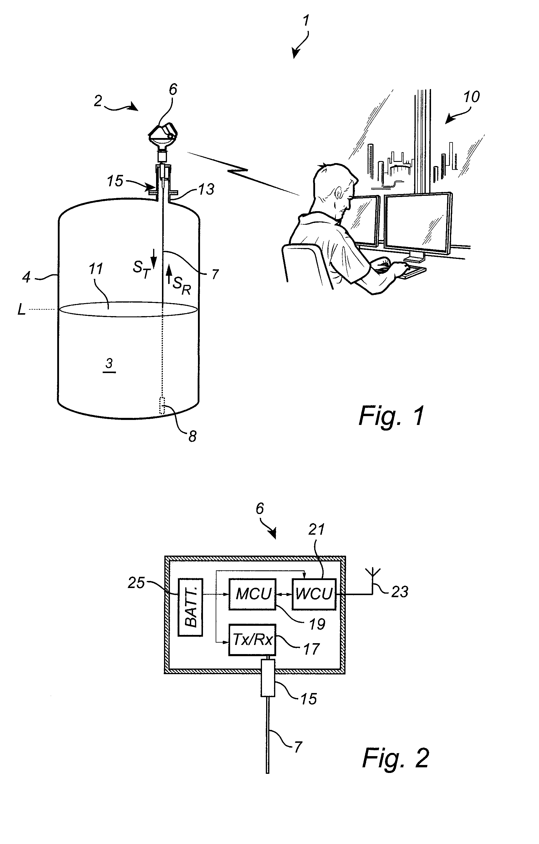
The present invention relates to a pulsed radar level gauge system, and to a method of determining a filling level of a product in a tank. Radar level gauge (RLG) systems are in wide use for determining filling levels in tanks. Radar level gauging is generally performed either by means of non-contact measurement, whereby electromagnetic signals are radiated towards the product in the tank, or by means of contact measurement, often referred to as guided wave radar (GWR), whereby electromagnetic signals are guided towards and into the product by a probe acting as a waveguide. The probe is generally arranged to extend vertically from the top towards the bottom of the tank. An electromagnetic transmit signal is generated by a transceiver and propagated towards the surface of the product in the tank, and an electromagnetic reflection signal resulting from reflection of the transmit signal at the surface is received by the transceiver. Based on the transmit signal and the reflection signal, the distance to the surface of the product can be determined. Most radar level gauge systems on the market today are either so-called pulsed radar level gauge systems that determine the distance to the surface of the product in the tank based on the difference in time between transmission of a pulse and reception of its reflection at the surface of the product, or systems that determine the distance to the surface based on the frequency difference between a transmitted frequency-modulated signal and its reflection at the surface. The latter type of system is generally referred to as being of the FMCW (Frequency Modulated Continuous Wave) type. For pulsed radar level gauge systems, time expansion techniques are generally used to resolve the time-of-flight. In such pulsed radar level gauge systems a transmit signal in the form of a first pulse train with a first pulse repetition frequency is propagated towards the surface of the product in the tank, and a surface reflection signal resulting from reflection at the surface is received. A reference signal in the form of a second pulse train having a second pulse repetition frequency, controlled to differ from the first pulse repetition frequency by a given frequency difference, is also generated. At the beginning of a measurement operation, the transmit signal and the reference signal are synchronized to have the same phase. Due to the difference in pulse repetition frequency, the phase difference between the transmit signal and the reference signal will gradually increase during the measurement operation. During the measurement operation, the surface reflection signal is correlated with the reference signal, to form a measurement signal based on a time correlation between the surface reflection signal and the reference signal. Based on the measurement signal, the filling level can be determined. In most existing pulsed radar level gauge systems, the transmit signal is provided in the form of so-called DC-pulses, which may exhibit a frequency spectrum of 0 GHz to about 1 GHz with a substantial amount of the transmitted power being close to 0 GHz. Accordingly, the relative bandwidth of such DC-pulses may be well in excess of 200%, which requires a wideband coupling between the transceiver (typically on the outside of the tank) and the propagation device (typically on the inside of the tank). However, design options for such a wideband coupling are limited, so that various interesting and otherwise advantageous coupling configurations are excluded. It would therefore be desirable to provide a radar level gauge system allowing the use of a more narrow-band coupling between the transceiver and the propagation device. In view of the above, a general object of the present invention is to provide an improved radar level gauge system, in particular allowing the use of a more narrow-band coupling between the transceiver and the propagation device. According to a first aspect of the present invention, it is provided a radar level gauge system for determining a filling level of a product in a tank, the radar level gauge system comprising: pulse generating circuitry for generating: an electromagnetic transmit signal in the form of a first pulse train having a first pulse repetition frequency, the first pulse train being formed by a time-sequence of substantially identical transmit pulses, each transmit pulse in the time-sequence of transmit pulses exhibiting a full period waveform; and an electromagnetic reference signal in the form of a second pulse train having a second pulse repetition frequency, the second pulse repetition frequency differing from the first pulse repetition frequency by a predetermined frequency difference, the second pulse train being formed by a time-sequence of substantially identical reference pulses, each reference pulse in the time-sequence of reference pulses exhibiting a half period waveform; a propagation device connected to the pulse generating circuitry and arranged to propagate the transmit signal towards a surface of the product in the tank, and to return a surface reflection signal resulting from reflection of the transmit signal at the surface; measurement circuitry connected to the propagation device and to the pulse generating circuitry for forming a measurement signal based on a time-correlation between the surface reflection signal and the reference signal; and processing circuitry connected to the measurement circuitry for determining the filling level based on the measurement signal. The tank may be any container or vessel capable of containing a product, and may be metallic, or partly or completely non-metallic, open, semi-open, or closed. Furthermore, the filling level of the product in the tank may be determined directly by using a signal propagation device propagating the transmit signal towards the product inside the tank, or indirectly by using a propagation device disposed inside a so-called chamber located on the outside of the tank, but being in fluid connection with the inside of the tank in such a way that the level in the chamber corresponds to the level inside the tank. The pulse generating circuitry may include at least one voltage controlled oscillator circuit, which may comprise a crystal oscillator. Alternatively, or in addition, the pulse generating circuitry may comprise at least one resonator element formed by electronic circuitry comprising a portion with inductive characteristics and a portion with capacitive characteristics. It should be noted that any one or several of the means comprised in the processing circuitry may be provided as either of a separate physical component, separate hardware blocks within a single component, or software executed by one or several microprocessors. The “measurement circuitry” may, for example, comprise a mixer and the measurement signal may be formed by mixing the reference signal and the surface reflection signal such that a signal indicating time correlation is generated each time a reference pulse passes the time domain for the surface reflection signal. As will be evident to those skilled in the relevant art, the measurement circuitry may, in principle, include any circuitry capable of time-correlating two signals. Various types of such circuitry are well-known from, for example, time-expansion oscilloscopes. That each transmit pulse exhibits a “full period waveform” should, in the context of the present application, be understood to mean that each transmit pulse exhibits a waveform shape with a crest and a trough. Analogously, each reference pulse exhibiting a “half period waveform” should, in the context of the present application, be understood to exhibit a waveform shape with only one of a crest and a trough. The determination of the filling level may be additionally based on the above-mentioned predetermined frequency difference. In embodiments where the propagation device is a probe, it should be understood that the probe is a waveguide designed for guiding electromagnetic signals. The probe may be rigid or flexible and may advantageously be made of metal, such as stainless steel. The present invention is based on the realization that the desired narrower relative bandwidth can be achieved by providing the transmit pulses as full period waveform pulses, while providing the reference pulses as half period waveform pulses. The present inventor has further realized that embodiments of the pulsed radar level gauge system providing the desired narrower relative bandwidth can be achieved through simple modification of existing pulsed radar level gauge systems, using so-called DC-pulses. According to various embodiments of the present invention, a pulse width of each transmit pulse in the time-sequence of transmit pulses may be at least approximately twice a pulse width of each reference pulse in the time-sequence of reference pulses. In these embodiments, the time-correlation of the surface reflection signal and the reference signal may be simplified. Furthermore, the above-mentioned half period waveform may advantageously be substantially identical to one half of the above-mentioned full period waveform. In other words, a reference pulse may be substantially identical to one half of a transmit pulse. Moreover, each transmit pulse in the time-sequence of transmit pulses may be sinusoidal; and each reference pulse in the time-sequence of reference pulses may be sinusoidal. Sinusoidal pulses in general require a narrower bandwidth than square wave pulses, which may be advantageous for embodiments of the present invention. It should be understood that the term “sinusoidal” is not limited to a simple sine wave, but more broadly denotes a smooth waveform that can be formed by superimposing a limited number of sine waves with different frequencies. In various embodiments of the radar level gauge system according to the present invention, furthermore, the pulse generating circuitry may comprise a first pulse generator for generating an intermediate signal in the form of an intermediate pulse train having the first pulse repetition frequency, the intermediate pulse train being formed by a time-sequence of substantially identical intermediate pulses, each intermediate pulse in the time-sequence of intermediate pulses exhibiting a half period waveform; and a waveform converter connected to the first pulse generator for receiving the time-sequence of intermediate pulses and providing the time-sequence of transmit pulses. Through this configuration of the radar level gauge system, an existing pulsed radar level gauge system layout can be modified to achieve a narrower bandwidth with very limited intervention. For instance, existing pulse generating circuitry for generating DC-pulses can be modified through addition of the above-mentioned waveform converter, to convert the half period waveform DC-pulses to full period waveform pulses exhibiting a considerably smaller relative bandwidth. In embodiments, the above-mentioned waveform converter may comprise differentiator circuitry for differentiating (forming a time derivative of) the intermediate half period waveform signal. The differentiator circuitry may include an active or a passive differentiator. In its simplest form, which is still estimated to exhibit sufficient performance, the differentiator circuitry may be provided in the form of a coupling capacitor connected in series between the first pulse generator and the propagation device, possibly in combination with one or a few further passive components. As is well known, a few extra circuit elements can be included to improve the result of a pulse forming circuit. As an alternative or complement to discrete passive circuit elements, distributed elements like a piece of transmission line can be used. In other embodiments of the radar level gauge system according to the present invention, the waveform converter may comprise delay circuitry connected to the first pulse generator for providing a first intermediate signal with a first delay, and a second intermediate signal with a second delay different from the first delay; and a differential amplifier connected to the delay circuitry to receive the first intermediate signal and the second intermediate signal, and to provide the transmit signal as a difference signal between the first intermediate signal and the second intermediate signal. The delay circuitry may include parallel branches with different delay connected to the output of the pulse generator. One of the delays may be substantially zero (constituted by a simple conductor, such as a circuit board trace). In various embodiments of the radar level gauge system according to the present invention, the pulse generating circuitry may further comprise: a second pulse generator for generating the reference signal; and timing circuitry for controlling the first pulse generator and the second pulse generator to provide the predetermined frequency difference. In other embodiments, the radar level gauge system may comprise a single pulse generator for generating the transmit pulses (the intermediate pulses) and the reference pulses, and a controllable delay circuit for controllably delaying at least one of the transmit signal (intermediate signal) and the reference signal. Furthermore, the above-mentioned measurement circuitry may comprise correlating circuitry for time-correlating the surface reflection signal and the reference signal to form a correlation signal, on which the measurement signal is based. One example of such correlating circuitry is sampling circuitry for sampling the surface reflection signal at sampling times determined by the timing of the reference pulses. For instance, the reference pulses may be used to trigger the sampling circuitry. In embodiments, the measurement circuitry may further comprise integrating circuitry for integrating the correlation signal to form the measurement signal. Integration of the correlation signal may allow use of the same kind of processing of the measurement signal as in existing pulsed radar level gauge systems. In addition, the integration is expected to remove noise, especially short noise “spikes”. In various embodiments, furthermore, the radar level gauge system according to the present invention may further comprise a non-conducting signal coupling arrangement connected between the propagation device, and the pulse generating circuitry and the measurement circuitry. The non-conducting signal coupling arrangement may, for instance, comprise a reactive signal coupling for coupling the transmit signal from transceiver to propagation device (typically probe). The reactive signal coupling may use inductive and/or capacitive coupling. For a so-called guided wave radar level gauge system (comprising a probe), the provision of such a non-conductive signal coupling, may allow the probe to be grounded through direct conductive connection to a metallic tank structure. This, in turn, provides for a very robust attachment of the probe to the tank, and also considerably increases the tolerance of the radar level gauge system to current spikes, such as spikes due to lightning. Examples of non-conductive signal coupling configurations that may be suitable are described in US 2009/0085794, which is hereby incorporated by reference in its entirety. According to a second aspect of the present invention, it is provided a method of determining a filling level of a product in a tank using a radar level gauge system comprising pulse generating circuitry, a propagation device, measurement circuitry, and processing circuitry, the method comprising the steps of: generating, by the pulse generating circuitry, an electromagnetic transmit signal in the form of a first pulse train having a first pulse repetition frequency, the first pulse train being formed by a time-sequence of substantially identical transmit pulses, each transmit pulse in the time-sequence of transmit pulses exhibiting a full period waveform; generating, by the pulse generating circuitry, an electromagnetic reference signal in the form of a second pulse train having a second pulse repetition frequency, the second pulse repetition frequency differing from the first pulse repetition frequency by a predetermined frequency difference, the second pulse train being formed by a time-sequence of substantially identical reference pulses, each reference pulse in the time-sequence of reference pulses exhibiting a half period waveform; propagating, by the propagation device, the transmit signal towards a surface of the product in the tank; propagating, by the propagation device, a surface reflection signal resulting from reflection of the transmit signal at the surface; receiving, by the measurement circuitry, the surface reflection signal; time-correlating, by the measurement circuitry, the surface reflection signal and the reference signal to form a measurement signal; and determining, by the processing circuitry, the filling level based on the measurement signal. In embodiments, the method may further comprise the steps of: non-conductively coupling the transmit signal between the pulse generating circuitry and the propagation device; and non-conductively coupling the surface reflection signal between the propagation device and the measurement circuitry. In summary, the present invention thus relates to a radar level gauge system comprising: pulse generating circuitry for generating an electromagnetic transmit signal in the form of a first pulse train formed by a time-sequence of substantially identical transmit pulses, each exhibiting a full period waveform; and an electromagnetic reference signal in the form of a second pulse train formed by a time-sequence of substantially identical reference pulses, each exhibiting a half period waveform; a propagation device arranged to propagate the transmit signal towards a product in a tank, and to return a surface reflection signal resulting from reflection of the transmit signal at a surface of the product; measurement circuitry for forming a measurement signal based on a time-correlation between the surface reflection signal and the reference signal; and processing circuitry connected to the measurement circuitry for determining the filling level based on the measurement signal. These and other aspects of the present invention will now be described in more detail, with reference to the appended drawings showing example embodiments of the invention, wherein: In the present detailed description, various embodiments of the present invention are mainly discussed with reference to a pulsed radar level gauge system with a non-conductive coupling between transceiver and probe. It should be noted that this by no means limits the scope of the present invention, which also covers a pulsed radar level gauge system with other couplings between transceiver and probe, such as a conventional conductive coupling between transceiver and probe. The radar level gauge system 2 of GWR (Guided Wave Radar) type is installed at a tank 4 having a tubular mounting structure 13 (often referred to as a “nozzle”) extending substantially vertically from the roof of the tank 4. The radar level gauge system 2 is installed to measure the filling level of a product 3 in the tank 4. The radar level gauge system 2 comprises a measuring unit 6 and a propagation device in the form of a single conductor probe 7 extending from the measuring unit 6, through the tubular mounting structure 13, towards and into the product 3. In the example embodiment in By analyzing transmitted signals STbeing guided by the probe 7 towards the surface 11 of the product 3, and reflected signals SRtraveling back from the surface 11, the measurement unit 6 can determine the filling level of the product 3 in the tank 4. It should be noted that, although a tank 4 containing a single product 3 is discussed herein, the distance to any material interface along the probe can be measured in a similar manner. The radar level gauge system in Referring to the schematic block diagram in As is schematically illustrated in The MCU 19 determines the filling level of the product 3 in the tank 4 and provides a value indicative of the filling level to an external device, such as a control center, from the MCU 19 via the WCU 21 through the communication antenna 23. The radar level gauge system 1 may advantageously be configured according to the so-called WirelessHART communication protocol (IEC 62591). Although the measurement unit 6 is shown to comprise an energy store 25 and to comprise devices (such as the WCU 21 and the communication antenna 23) for allowing wireless communication, it should be understood that power supply and communication may be provided in a different way, such as through communication lines (for example 4-20 mA lines). The local energy store need not (only) comprise a battery, but may alternatively, or in combination, comprise a capacitor or super-capacitor. The radar level gauge system 2 in Referring now to As is schematically shown in As is schematically indicated in The transmitter branch comprises the first pulse forming circuit 29, and the receiver branch comprises the second pulse forming circuit 31 and measurement circuitry 33. As is schematically indicated in Additionally, as was briefly described above with reference to When the radar level gauge system 1 in The time-expansion technique that was briefly described in the previous paragraph is well known to the person skilled in the art, and is widely used in pulsed radar level gauge systems. As is clear from the above discussion, the output from the mixer 37 will be a sequence of values, where each value represents a time correlation between a pulse of the reference signal SREFand the surface reflection signal SR. The values in this sequence of values are tied together to form a continuous signal using the sample-and-hold circuit 39. In this context it should be noted that the sample-and-hold amplifier 39 is simply an illustrative example of a device capable of maintaining a voltage level over a given time, and that there are various other devices that can provide the desired functionality, as is well known to the person skilled in the art. In the example embodiment of As is schematically indicated in The reference signal SREFis initially in phase with the transmit signal, but will, due to its lower pulse repetition frequency “run away from” the transmit signal STand “catch up with” the surface reflection signal SR. When the time-varying phase difference between the transmit signal STand the reference signal SREFcorresponds to the time-of-flight of the reflected signal SR, there will be a time-correlation between pulses of the reference signal SREFand pulses of the surface reflection signal SR. This time-correlation, results in a time-expanded correlation signal Sc, which can, in turn, be converted to a measurement signal SMas will be described further below with reference to First, however, example waveforms of the transmit pulses 45 and the reference pulses 47 will be described with reference to the schematic magnified view in As was explained in the Summary section, the full period waveform of the transmit pulses 45 considerably reduces the relative bandwidth of the transmit signal STas compared to conventional DC-pulses (such as the reference pulses 47 shown in Referring now to Following integration by integrator 43 and amplification by LNA 41, the measurement signal SMin It should be noted that the present invention is equally applicable to pulsed level gauge systems in which the time-varying phase difference between the transmit signal STand the reference signal SREFis achieved by providing the reference signal as the transmit signal being delayed by a time varying delay, or vice-versa. Different example configurations of the first pulse generator 29 in Referring first to Turning to A first example of the connection arrangement 15 comprised in the radar level gauge system 2 in The feed-through member 71 extends from a first end 77 on an outside of the tank 4 to a second end 79 on an inside of the tank 4. The probe 7 is conductively connected to the feed-through member 71, and extends towards the product in the tank 4 from the second end 79 of the feed-through member 71. In the example configuration of the connection arrangement 15 in The feed-through member 71 is in conductive contact with a conductive lid 81 at a grounding position 83. As is indicated in In the example configuration of the connection arrangement 15 shown in The signal conductor 73 extends through the feed-through member 71 from the outside of the tank 4 to the inside of the tank 4. In the example configuration schematically shown in As is schematically indicated in The tank coupling arrangement 76 is connected to the signal conductor 73 on the inside of the tank, and is configured to provide inductive and capacitive coupling in series between the signal conductor 73 and the inner wall of the tubular member 82. In the example configuration of the connection arrangement in In the example embodiment in As is schematically indicated in A simulation performed for dimensions such as those shown in An example embodiment of the method according to the present invention will now be described with reference to the flow-chart in In step 100, the transmit signal STis generated as a pulse train of transmit pulses 45, each exhibiting a full period waveform, and thus having a relatively small relative bandwidth. In step 101, taking place at the same time as step 100, the reference signal SREFis generated as a pulse train of reference pulses 47, each exhibiting a half period waveform. In step 102, the transmit signal STis propagated towards the surface 11 of the product 3 in the tank 4, and in step 103, the surface reflection signal SRresulting from reflection at the surface 11 of the transmit signal STis received by the transceiver 17. In step 104, the surface reflection signal SRand the reference signal SREFare time-correlated to form the time-expanded measurement signal SM, and in step 105, the filling level is determined based on the measurement signal SMand the frequency difference Δf between the pulse repetition frequency of the transmit signal STand the pulse repetition frequency of the reference signal SREF. The person skilled in the art realizes that the present invention by no means is limited to the preferred embodiments described above. For example, many other configurations of the connection arrangement 15 may be feasible. In particular, many other configurations of the tank coupling arrangement 76 and the connection of the feed-through member 71 to the tank 4 will be possible. Moreover, many other pulse shapes of the transmit signal STand the reference signal SREFmay be beneficial. A radar level gauge system comprising: pulse generating circuitry for generating an electromagnetic transmit signal in the form of a first pulse train formed by a time-sequence of substantially identical transmit pulses, each exhibiting a full period waveform; and an electromagnetic reference signal in the form of a second pulse train formed by a time-sequence of substantially identical reference pulses, each exhibiting a half period waveform; a propagation device arranged to propagate the transmit signal towards a product in a tank, and to return a surface reflection signal resulting from reflection of the transmit signal at a surface of the product; measurement circuitry for forming a measurement signal based on a time-correlation between the surface reflection signal and the reference signal; and processing circuitry connected to the measurement circuitry for determining the filling level based on the measurement signal. 1. A radar level gauge system for determining a filling level of a product in a tank, said radar level gauge system comprising:
pulse generating circuitry for generating:
an electromagnetic transmit signal in the form of a first pulse train having a first pulse repetition frequency, said first pulse train being formed by a time-sequence of substantially identical transmit pulses, each transmit pulse in said time-sequence of transmit pulses exhibiting a full period waveform; and an electromagnetic reference signal in the form of a second pulse train having a second pulse repetition frequency, said second pulse repetition frequency differing from said first pulse repetition frequency by a predetermined frequency difference, said second pulse train being formed by a time-sequence of substantially identical reference pulses, each reference pulse in said time-sequence of reference pulses exhibiting a half period waveform; a propagation device connected to said pulse generating circuitry and arranged to propagate said transmit signal towards a surface of said product in the tank, and to return a surface reflection signal resulting from reflection of said transmit signal at said surface; measurement circuitry connected to said propagation device and to said pulse generating circuitry for forming a measurement signal based on a time-correlation between said surface reflection signal and said reference signal; and processing circuitry connected to said measurement circuitry for determining said filling level based on said measurement signal. 2. The radar level gauge system according to 3. The radar level gauge system according to 4. The radar level gauge system according to each transmit pulse in said time-sequence of transmit pulses is sinusoidal; and each reference pulse in said time-sequence of reference pulses is sinusoidal. 5. The radar level gauge system according to a first pulse generator for generating an intermediate signal in the form of an intermediate pulse train having said first pulse repetition frequency, said intermediate pulse train being formed by a time-sequence of substantially identical intermediate pulses, each intermediate pulse in said time-sequence of intermediate pulses exhibiting a half period waveform; and a waveform converter connected to said first pulse generator for receiving said time-sequence of intermediate pulses and providing said time-sequence of transmit pulses. 6. The radar level gauge system according to 7. The radar level gauge system according to 8. The radar level gauge system according to 9. The radar level gauge system according to delay circuitry connected to said first pulse generator for providing a first intermediate signal with a first delay, and a second intermediate signal with a second delay different from said first delay; and a differential amplifier connected to said delay circuitry to receive said first intermediate signal and said second intermediate signal, and to provide said transmit signal as a difference signal between said first intermediate signal and said second intermediate signal. 10. The radar level gauge system according to a second pulse generator for generating said reference signal; and timing circuitry for controlling said first pulse generator and said second pulse generator to provide said predetermined frequency difference. 11. The radar level gauge system according to 12. The radar level gauge system according to 13. The radar level gauge system according to 14. The radar level gauge system according to 15. The radar level gauge system according to 16. A method of determining a filling level of a product in a tank using a radar level gauge system comprising pulse generating circuitry, a propagation device, measurement circuitry, and processing circuitry, said method comprising the steps of:
generating, by said pulse generating circuitry, an electromagnetic transmit signal in the form of a first pulse train having a first pulse repetition frequency, said first pulse train being formed by a time-sequence of substantially identical transmit pulses, each transmit pulse in said time-sequence of transmit pulses exhibiting a full period waveform; generating, by said pulse generating circuitry, an electromagnetic reference signal in the form of a second pulse train having a second pulse repetition frequency, said second pulse repetition frequency differing from said first pulse repetition frequency by a predetermined frequency difference, said second pulse train being formed by a time-sequence of substantially identical reference pulses, each reference pulse in said time-sequence of reference pulses exhibiting a half period waveform; propagating, by said propagation device, said transmit signal towards a surface of said product in the tank; propagating, by said propagation device, a surface reflection signal resulting from reflection of said transmit signal at said surface; receiving, by said measurement circuitry, said surface reflection signal; time-correlating, by said measurement circuitry, said surface reflection signal and said reference signal to form a measurement signal; and determining, by said processing circuitry, said filling level based on said measurement signal. 17. The method according to non-conductively coupling said transmit signal between said pulse generating circuitry and said probe; and non-conductively coupling said surface reflection signal between said probe and said measurement circuitry. 101-117. (canceled)TECHNICAL FIELD OF THE INVENTION
TECHNICAL BACKGROUND
SUMMARY OF THE INVENTION
BRIEF DESCRIPTION OF THE DRAWINGS
DETAILED DESCRIPTION OF AN EXAMPLE EMBODIMENT OF THE INVENTION