ONE-WAY CLUTCH TYPE VARIABLE VALVE TIMING DEVICE AND ENGINE SYSTEM HAVING THE SAME
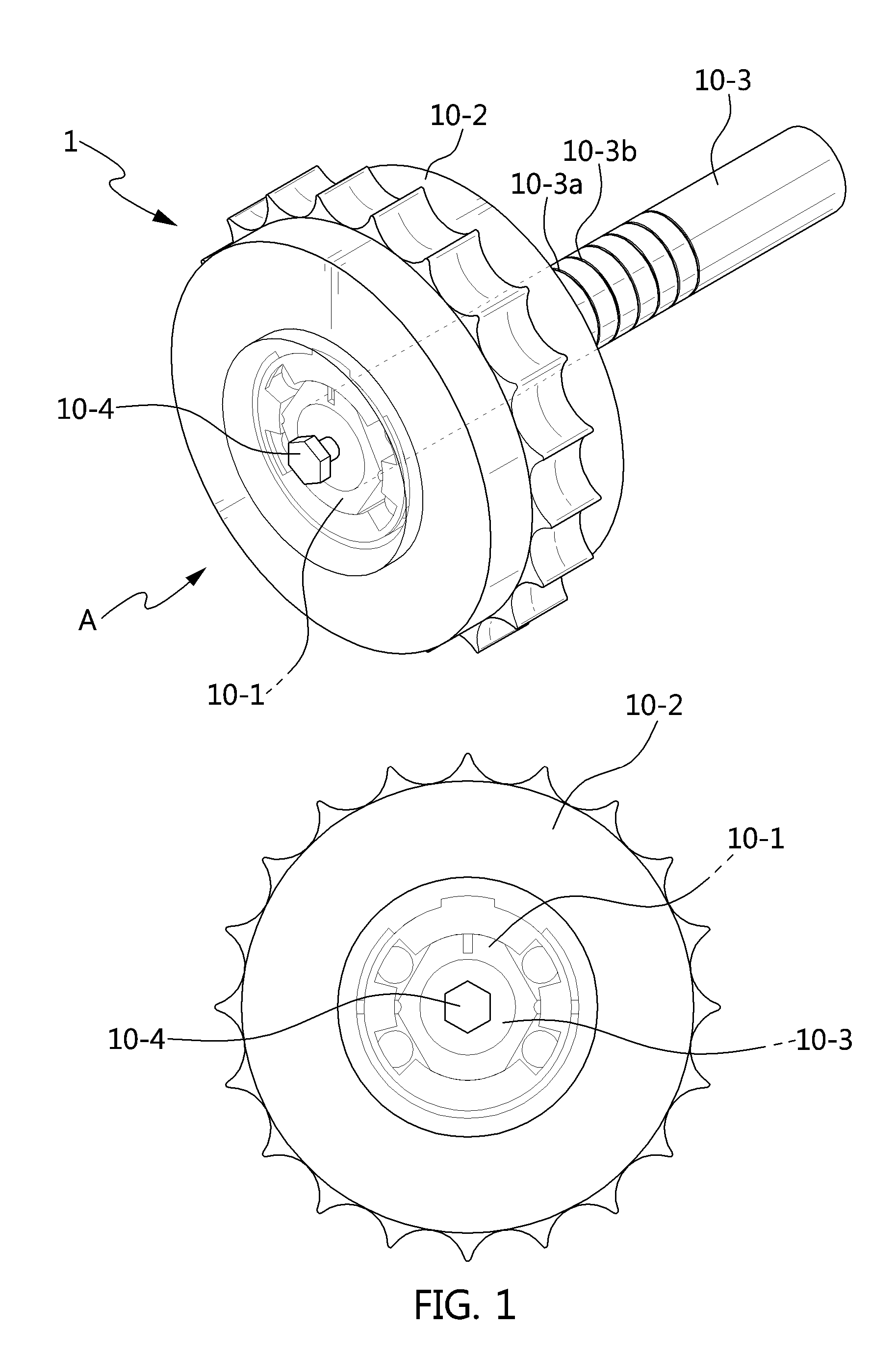
The present application claims priority to Korean Patent Application No. 10-2017-0082574, filed on Jun. 29, 2017, the entire contents of which is incorporated herein for all purposes by this reference. The present invention relates to a variable valve timing device; and, more particularly, to an engine system having a variable valve timing device in which a one-way clutch is applied to a rotor connected to a camshaft. In general, a variable valve timing device controls a phase of a camshaft that opens and closes intake and exhaust valves. In the present case, the variable valve timing device is a continuously variable valve timing (hereinafter, referred to as “CVVT”) device that directly controls a camshaft to adjust an advanced/retarded phase timings of a cam, and may include a continuously variable valve duration (CVVD) in which valve duration is controlled without a change in valve lift, and a continuously variable valve lift (CVVL) in which valve duration is controlled by changing valve lift. To the present end, the CVVT device is configured to directly connect a rotor, which rotates in clockwise/counterclockwise directions by torque generated when a valve is opened and closed along with a rotation of a camshaft, to the camshaft. The CVVT is classified as a hydraulic CVVT device and an electric CVVT device according to the method of controlling the rotation of the rotor in the clockwise/counterclockwise directions for controlling the phase of the camshaft. For example, the hydraulic CVVT device controls the phase of the camshaft by rotating a rotor vane using the pressure of oil supplied to advance/retard grooves formed in a camshaft journal. On the other hand, the electric CVVT device is classified into a friction clutch type CVVT device that controls the phase of the camshaft using a friction clutch, and a motor type CVVT device that controls the phase of the camshaft using an electric motor. Accordingly, each of the hydraulic CVVT device, the friction clutch type CVVT device, and the motor type CVVT device optimally control the opening or closing timings of intake and exhaust valves according to the revolutions per minute (RPM) of an engine by directly controlling the camshaft, achieving an improvement in fuel efficiency of the engine, an reduction in emissions, an increase in low-speed torque, and an improvement in power. However, the hydraulic CVVT device consumes too much oil and has a limited response due to oil pressure while an intermediate phase is restrictively fixed when the engine is started. The friction clutch type CVVT device deteriorates clutch durability due to the friction clutch and fuel efficiency due to an increase in driving friction of the camshaft. The motor type CVVT device has an advantage in that it has a rapid response and an intermediate phase is fixable when the engine is started by the electric motor, but has a disadvantage in that it has a complicated structure/control and is expensive to produce and/or maintain. The information included in this Background of the Invention section is only for enhancement of understanding of the general Background of the Invention and may not be taken as an acknowledgement or any form of suggestion that this information forms the prior art already known to a person skilled in the art. Various aspects and exemplary embodiments of the present invention are directed to providing a one-way clutch type variable valve timing device configured for restricting clockwise/counterclockwise rotation of a rotor by torque of a camshaft acting as a rotation shaft using a one-way clutch, achieving an improvement in fuel efficiency/emission material (EM) of an engine in addition to improving a phase setting degree of freedom and expanding a phase shift with respect to the camshaft when the engine is started, and realizing a rapid response and intermediate phase starting and increasing a phase range with low cost, and an engine system having the same. Other various aspects of the present invention can be understood by the following description, and become apparent with reference to the exemplary embodiments of the present invention. Also, it is obvious to those skilled in the art to which the present invention pertains that the objects and advantages of the present invention can be realized by the means as claimed and combinations thereof. In accordance with various exemplary embodiments of the present invention, a variable valve timing device may include a rotor rotated in clockwise and counterclockwise directions together with a supply of oil thereto, a one-way clutch coupled to the rotor to limit an amount of rotation of the rotor, a sprocket having a rotor hole surrounding an external diameter portion of the rotor, a rotation shaft fitted into a shaft hole of the rotor for the supply of oil to an oil groove, and a shaft fixing member coupled to the rotation shaft to fix the rotor and the rotation shaft. The one-way clutch may include a carrier, a position of which is controlled by hydraulic action to form left and right chambers filled with the oil, a ball disposed in a ball slot of the carrier, a stopper carrier protruding from the carrier to limit the amount of rotation of the rotor, and a spring supported by a vane. The rotor may have a rotor body having a shaft hole formed in a center thereof, the carrier may surround an external diameter portion of the rotor body, the ball may come into contact with an external peripheral surface of the rotor body, and the vane may be fixed on the external peripheral surface of the rotor body. The rotor body may have a hexagonal shape and have an oil outlet hole radially formed therein, the hexagonal rotor body may have upper and lower sealing surfaces formed to seal the center thereof and left and right clutch acting surfaces, the ball coming into contact with the left and right clutch acting surfaces, and a fixed slit may be recessed on one of the upper and lower sealing surfaces, the vane being fixed into the fixed slit. The oil may be discharged from an internal diameter portion of the rotor body to the external diameter portion thereof through the oil outlet hole. The rotor body may have a rotor flange formed at an intermediate portion thereof, and the one-way clutch may include a front one-way clutch provided at a left side of the rotor flange and a rear one-way clutch provided at a right side of the rotor flange. Alternatively, the rotor body may have left and right rotor flanges formed at both end portions thereof, and the one-way clutch may include front and rear one-way clutches facing each other between the left and right rotor flanges. In accordance with various exemplary embodiments of the present invention, an engine system may include a variable valve timing device including a rotor, an internal diameter portion of which is coupled with a camshaft, which has a cam for opening or closing intake and exhaust valves and advance and retard oil grooves formed for the supply of oil and which is connected to a crankshaft by a chain, while a sprocket is coupled to an external diameter portion of the rotor, and a pair of front and rear one-way clutches coupled to the rotor form left and right chambers filled with the oil, a hydraulic circuit configured to supply the oil to the camshaft, and an electronic control unit (ECU) configured to control the hydraulic circuit for the supply of oil. The rotor may have a hexagonal rotor body, and the hexagonal rotor body may have upper and lower sealing surfaces formed to seal the center thereof and left and right clutch acting surfaces acting on the respective front and rear one-way clutches. The front one-way clutch may include a carrier surrounding one portion of the rotor body to form left and right chambers filled with the oil while a position of the carrier is controlled by the pressure of the oil, a ball located in a ball slot of the carrier to come into contact with an external peripheral surface of the rotor body, a stopper carrier protruding from the carrier to limit an amount of rotation of the rotor body, the stopper carrier being coupled to a stopper groove of the sprocket, and a spring supported by a vane fixed on the external peripheral surface of the rotor body. The rear one-way clutch may include a carrier surrounding the other portion of the rotor body to form left and right chambers filled with the oil while a position of the carrier is controlled by the pressure of the oil, a ball located in a ball slot of the carrier to come into contact with an external peripheral surface of the rotor body, a stopper carrier protruding from the carrier to limit an amount of rotation of the rotor body, and a spring supported by a vane fixedly fitted into a fixed slit formed on one of the upper and lower sealing surfaces of the rotor body. The rotor may be fixed by a shaft fixing member fastened to the camshaft in a state in which front and rear covers are coupled to both left and right sides of the rotor. The rotor may include a rotor body having an oil outlet hole radially formed therein for discharge of the oil, the front and rear one-way clutches being coupled to the rotor body, and a rotor flange forming a concentric circle at an intermediate portion of the rotor body to separate the front and rear one-way clutches from each other. Alternatively, the rotor may include a rotor body having an oil outlet hole radially formed therein for the discharge of oil, the front and rear one-way clutches being coupled to the rotor body, and rotor flanges forming a concentric circle at both end portions of the rotor body to surround the front and rear one-way clutches. The hydraulic circuit may include an oil pump operated by control of the ECU to pump the oil, an oil line leading from the oil pump to the camshaft wherein the oil is supplied to the rotor through the camshaft, and an oil-flow control valve configured to open or close the oil line by control of the ECU to control supply of the oil. The methods and apparatuses of the present invention have other features and advantages which will be apparent from or are set forth in more detail in the accompanying drawings, which are incorporated herein, and the following Detailed Description, which together serve to explain certain principles of the present invention. It should be understood that the appended drawings are not necessarily to scale, presenting a somewhat simplified representation of various features illustrative of the basic principles of the invention. The specific design features of the present invention as included herein, including, for example, specific dimensions, orientations, locations, and shapes will be determined in part by the particularly intended application and use environment. In the figures, reference numbers refer to the same or equivalent parts of the present invention throughout the several figures of the drawing. Reference will now be made more specifically to various embodiments of the present invention(s), examples of which are illustrated in the accompanying drawings and described below. While the invention(s) will be described in conjunction with exemplary embodiments, it will be understood that the present description is not intended to limit the invention(s) to those exemplary embodiments. On the other hand, the invention(s) is/are intended to cover not only the exemplary embodiments, but also various alternatives, modifications, equivalents and other embodiments, which may be included within the spirit and scope of the invention as defined by the appended claims. Referring to For example an external diameter portion of the rotor device 10-1 is coupled to the sprocket 10-2 and an internal diameter portion thereof is coupled to the rotation shaft 10-3. The sprocket 10-2 has sprocket teeth, which are formed on an external diameter portion thereof and is chained to an external rotary device, to rotate the rotation shaft 10-3 together with the rotor device 10-1. The rotation shaft 10-3 is coupled to the rotor device 10-1 to rotate along with the rotor device 10-1 when the sprocket 10-2 rotates, and supplies an oil pressure from an external source to internal components of the rotor device 10-1. The shaft fixing member 10-4 is fastened to the rotation shaft 10-3 in the rotor device 10-1 fixing the rotor device 10-1 to the rotation shaft 10-3. In the assembly structure of the rotor device 10-1, the sprocket 10-2, the rotation shaft 10-3, and the shaft fixing member 10-4, which are components of the rotor device 10-1, are configured as follows. The sprocket 10-2 has the sprocket teeth formed on the external diameter portion thereof and a rotor hole 10-2 The rotation shaft 10-3 has advance and retard oil grooves 10-3 The shaft fixing member 10-4 has a typical bolt shape, and is screwed to the bolt groove 10-3 In the detailed structure of the rotor device 10-1, the rotor 20, the front and rear one-way clutches 30-1 and 30-2 that are respectively coupled to the left and right of the rotor 20, and the front and rear covers 40-1 and 40-2 that, respectively cover the front and rear one-way clutches 30-1 and 30-2 are configured as follows. The rotor 20 includes a rotor body 21 having the shaft hole 21 Furthermore, the rotor 20 is further formed with an oil outlet hole 21 For example, each of the left and right clutch acting surfaces 25 The front and rear one-way clutches 30-1 and 30-2 have the same component, namely each of the front and rear one-way clutches 30-1 and 30-2 includes a carrier 31, ball slots 31 For example, the carrier 31 has an annular flange having a predetermined width and thickness to have four ball slots 31 The balls 32 are four to be fitted into the four ball slots 31 Each of the front and rear covers 40-1 and 40-2 has a disk shape. The front cover 40-1 is disposed toward the front one-way clutch 30-1 to cover the front one-way clutch 30-1, whereas the rear cover 40-2 is located toward the rear one-way clutch 30-2 to cover the rear one-way clutch 30-2. To the present end, the front cover 40-1 has a bolt hole 40- In Meanwhile, Referring to More specifically, the variable valve timing device 1 includes the rotor device 10-1 having front and rear one-way clutches 30-1 and 30-2 and front and rear covers 40-1 and 40-2, the sprocket 10-2, the rotation shaft 10-3, and the shaft fixing member 10-4, as described with reference to The variable valve timing device 1 includes continuously variable valve timing (CVVT) that directly controls the camshaft to adjust the advanced/retarded phase timings of a cam, continuously variable valve duration (CVVD) in which valve duration is controlled without a change in valve lift, and continuously variable valve lift (CVVL) in which valve duration is controlled by changing valve lift. More specifically, the crankshaft 110 is rotated by reciprocating motion of the piston of the engine. The crank position detector 110-1 is configured to detect the speed of the crankshaft 110 to determine the revolutions per minute of the engine. The camshaft 120 is connected to the crankshaft 110 by the timing chain to be synchronized with the crankshaft 110, is coupled to the variable valve timing device 1 by a cam journal 121 forming advance and retard oil grooves 10-3 More specifically, the hydraulic circuit 130 supplies oil to the advance and retard oil grooves 10-3 More specifically, the ECU 170 controls a timing by controlling a cam phase by respective detected values of the crank position detector 110-1 and the cam position detector 120-1, and is configured to control operations of the oil pump 140 and the oil-flow control valve 150 by pulse width modulation (PWM) duty as a control signal. Accordingly, oil is pumped by the oil pump and flows to an advance groove line 160-1 and a retard groove line 160-2 via the oil control valve 150. The oil discharged from the advance groove line 160-1 is supplied to the advance oil groove 10-3 Furthermore, springs 33 included in the respective front and rear one-way clutches 30-1 and 30-2 form spring forces in opposite directions due to a difference in position with respect to vanes 34. That is, the spring 33 of the front one-way clutch 30-1 applies the spring force to the vane 34 in the clockwise direction thereof, wherein the spring 33 of the rear one-way clutch 30-2 applies the spring force to the vane 34 in the counterclockwise direction thereof. Such a spring force acts as a bias pressure. Hereinafter, the oil flowing to the advance oil groove 121-1 of the cam journal 121 is defined as grv_1, the oil flowing to the retard oil groove 121-2 of the cam journal 121 is defined as grv_2, the oil-filled left chamber of the carrier 31 of the front one-way clutch 30-1 is defined as cb_f1, the oil-filled right chamber of the carrier 31 of the front one-way clutch 30-1 is defined as cb_f2, the oil-filled left chamber of the carrier 31 of the rear one-way clutch 30-2 is defined as cb_r1, and the oil-filled right chamber of the carrier 31 of the rear one-way clutch 30-2 is defined as cb_r2. Accordingly, the grv_1 flows to the cb_f1 and the cb_r1 through the camshaft 120 and the rotor 20 for transfer of an oil pressure, and the grv_2 flows to the cb_f2 and the cb_r2 through the camshaft 120 and the rotor 20 for transfer of an oil pressure. The spring 33 of the front one-way clutch 30-1 is defined as spr_fr, the spring 33 of the rear one-way clutch 30-2 is defined as spr_rr, and the bias pressure corresponding to the spring force is defined as Pb. As a result, grv_1 and grv_2 form the following relationship: Here, the symbol “<” is a sign of inequality indicative of the size between two values, “A<B” signifies that B is a larger value than A, the symbol “−” is a minus sign, and the symbol “+” is a plus sign. The following Table 1 is an example of the result of controlling the cam phase generated by an operation of the front and rear one-way clutches 30-1 and 30-2 in a response to hydraulic control signals. In Table 1, CCW: counterclockwise, and CW: clockwise. As illustrated in the drawing, in the relationship of “cb_f1+Pb<cb_f2”, the counterclockwise rotation of the carrier 31 of each of the front and rear one-way clutches 30-1 and 30-2 is restricted, as illustrated in the left drawing of Accordingly, the stopper carrier 31 As described above, the variable valve timing device 1 applied to the engine system 100 according to the present exemplary embodiment includes the rotor 20, which is supplied with oil and is rotated in clockwise and counterclockwise directions, and the one-way clutches 30-1 and 30-2 which are coupled to the rotor 20 to limit an amount of rotation of the rotor. The one-way clutches 30-1 and 30-2 restrict the clockwise/counterclockwise rotation of the rotor 20 by the torque of the camshaft 120, achieving an improvement in fuel efficiency/emission material (EM) of the engine in addition to improving a phase setting degree of freedom and expanding a phase shift with respect to the camshaft 120 when the engine is started. It is possible to realize rapid response and intermediate phase starting and to increase a phase range with low cost. The variable valve timing device according to an exemplary embodiment of the present invention has a relatively simple structure and utilizes the one-way clutch as an already-tested mechanical element. Therefore, it is possible to freely configure the phase of the variable valve timing device when the engine is started, to increase a phase shift, and to significantly contribute to an improvement in fuel efficiency/EM of the engine. It is possible to realize rapid response and intermediate phase starting and to increase a phase range with low cost. Furthermore, since the opening or closing timings of the intake and exhaust valves are controlled by the variable valve timing device having the one-way clutch, it is possible to further achieve an improvement in fuel efficiency/EM of the engine. For convenience in explanation and accurate definition in the appended claims, the terms “upper”, “lower”, “up”, “down”, “upwards”, “downwards”, “internal”, “outer”, “inside”, “outside”, “inwardly”, “outwardly”, “internal”, “external”, “front”, “rear”, “back”, “forwards”, and “backwards” are used to describe features of the exemplary embodiments with reference the positions of such features as displayed in the figures. The foregoing descriptions of specific exemplary embodiments of the present invention have been presented for purposes of illustration and description. They are not intended to be exhaustive or to limit the invention to the precise forms disclosed, and obviously many modifications and variations are possible in light of the above teachings. The exemplary embodiments were chosen and described to explain certain principles of the invention and their practical application, to enable others skilled in the art to make and utilize various exemplary embodiments of the present invention, as well as various alternatives and modifications thereof. It is intended that the scope of the invention be defined by the Claims appended hereto and their equivalents. A variable valve timing device applied to an engine system may include a rotor supplied with oil and rotated in clockwise and counterclockwise directions, one-way clutches coupled to the rotor to limit an amount of rotation of the rotor, a sprocket having a rotor hole surrounding an external diameter portion of the rotor, a rotation shaft fitted into a shaft hole of the rotor for the supply of oil to oil grooves, and a shaft fixing member coupled to the rotation shaft to fix the rotor and the rotation shaft, wherein the one-way clutches restrict clockwise/counterclockwise rotation of the rotor by torque of a camshaft, achieving an improvement in fuel efficiency/emission material (EM) of an engine. 1. A variable valve timing device comprising:
a rotor device including a rotor rotatable in clockwise or counterclockwise direction with a supply of oil thereto, and a one-way clutch coupled to the rotor to limit an amount of rotation of the rotor. 2. The variable valve timing device of 3. The variable valve timing device of 4. The variable valve timing device of 5. The variable valve timing device of 6. The variable valve timing device of 7. The variable valve timing device of 8. The variable valve timing device of 9. The variable valve timing device of 10. The variable valve timing device of 11. An engine system comprising:
a variable valve timing device including a rotor, an internal diameter portion of which is coupled with a camshaft for supply of oil while a sprocket is coupled to an external diameter portion of the rotor, and a pair of front and rear one-way clutches coupled to the rotor to form first and second chambers filled with the oil; a hydraulic circuit configured to supply the oil to the camshaft; and an electronic control unit (ECU) configured to control the hydraulic circuit for the supply of the oil. 12. The engine system of 13. The engine system of the front one-way clutch includes a carrier surrounding a first portion of the rotor body to form first and second chambers filled with the oil while a position of the carrier controlled by pressure of the oil, a ball disposed in a ball slot of the carrier to contact with an external peripheral surface of the rotor body, a stopper carrier protruding from the carrier to limit an amount of rotation of the rotor body, and an elastic member supported by a vane fixed on the external peripheral surface of the rotor body; and the rear one-way clutch includes a carrier surrounding a second portion of the rotor body to form first and second chambers filled with the oil while the position of the carrier is controlled by the pressure of the oil, another ball located in a ball slot of the carrier to contact with an external peripheral surface of the rotor body, a stopper carrier protruding from the carrier to limit an amount of rotation of the rotor body, and an elastic member supported by a vane fixed on the external peripheral surface of the rotor body. 14. The engine system of 15. The engine system of 16. The engine system of 17. The engine system of 18. The engine system of 19. The engine system of 20. The engine system of CROSS-REFERENCE(S) TO RELATED APPLICATIONS
BACKGROUND OF THE INVENTION
Field of the Invention
Description of Related Art
BRIEF SUMMARY
BRIEF DESCRIPTION OF THE DRAWINGS
DETAILED DESCRIPTION
1) grv_2 < CCW (retard) CCW (retard) CCW (retard) grv_1 − Pb 2) grv_1 − CCW (retard) CW (advance) Fixed (when engine is Pb < grv_2 < stopped or normally grv_1 + Pb driven) 3) grv_1 + CW (advance) CW (advance) CW (advance) Pb < grv_2