Detection from Two Chrominance Directions
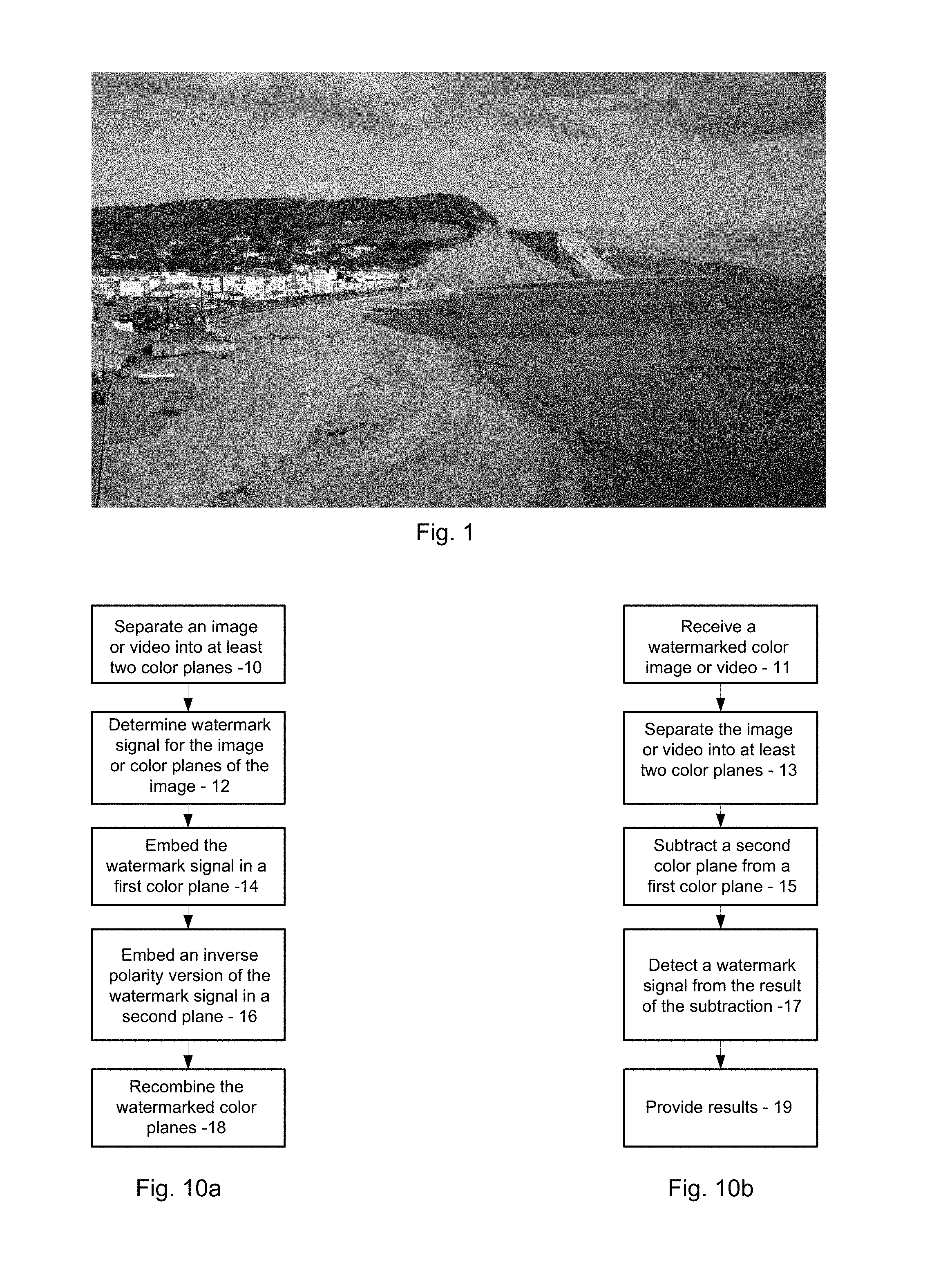
This application is a continuation of U.S. patent Ser. No. 15/445,874, filed Feb. 28, 2017 (U.S. Pat. No. 10,033,241) which is a continuation of U.S. patent Ser. No. 15/005,865, filed Jan. 25, 2016 (U.S. Pat. No. 9,582,844) which is a continuation of U.S. patent Ser. No. 14/189,617, filed Feb. 25, 2014 (U.S. Pat. No. 9,245,308) which is a continuation of U.S. patent application Ser. No. 13/494,849, filed Jun. 12, 2012 (U.S. Pat. No. 8,660,298), which is a continuation of U.S. patent application Ser. No. 12/634,505, filed Dec. 9, 2009 (U.S. Pat. No. 8,199,969), which is a continuation-in-part of U.S. patent application Ser. No. 12/337,029, filed Dec. 17, 2008 (U.S. Pat. No. 9,117,268). The above patent documents are each hereby incorporated herein by reference in its entirety. The present invention relates generally to steganographic data hiding and digital watermarking. The term “steganography” generally means data hiding. One form of data hiding is digital watermarking. Digital watermarking is a process for modifying media content to embed a machine-readable (or machine-detectable) signal or code into the media content. For the purposes of this application, the data may be modified such that the embedded code or signal is imperceptible or nearly imperceptible to a user, yet may be detected through an automated detection process. Most commonly, digital watermarking is applied to media content such as images, audio signals, and video signals. Digital watermarking systems may include two primary components: an embedding component that embeds a watermark in media content, and a reading component that detects and reads an embedded watermark. The embedding component (or “embedder” or “encoder”) may embed a watermark by altering data samples representing the media content in the spatial, temporal or some other domain (e.g., Fourier, Discrete Cosine or Wavelet transform domains). The reading component (or “reader” or “decoder”) analyzes target content to detect whether a watermark is present. In applications where the watermark encodes information (e.g., a message or payload), the reader may extract this information from a detected watermark. A watermark embedding process may convert a message, signal or payload into a watermark signal. The embedding process then combines the watermark signal with media content and possibly another signals (e.g., an orientation pattern or synchronization signal) to create watermarked media content. The process of combining the watermark signal with the media content may be a linear or non-linear function. The watermark signal may be applied by modulating or altering signal samples in a spatial, temporal or some other transform domain. A watermark encoder may analyze and selectively adjust media content to give it attributes that correspond to the desired message symbol or symbols to be encoded. There are many signal attributes that may encode a message symbol, such as a positive or negative polarity of signal samples or a set of samples, a given parity (odd or even), a given difference value or polarity of the difference between signal samples (e.g., a difference between selected spatial intensity values or transform coefficients), a given distance value between watermarks, a given phase or phase offset between different watermark components, a modulation of the phase of the host signal, a modulation of frequency coefficients of the host signal, a given frequency pattern, a given quantizer (e.g., in Quantization Index Modulation) etc. The present assignee's work in steganography, data hiding and digital watermarking is reflected, e.g., in U.S. Pat. Nos.: 6,947,571; 6,912,295; 6,891,959. 6,763,123; 6,718,046; 6,614,914; 6,590,996; 6,408,082; 6,122,403 and 5,862,260, and in published specifications WO 9953428 and WO 0007356 (corresponding to U.S. Pat. Nos. 6,449,377 and 6,345,104). Each of these patent documents is hereby incorporated by reference herein in its entirety. Of course, a great many other approaches are familiar to those skilled in the art. The artisan is presumed to be familiar with a full range of literature concerning steganography, data hiding and digital watermarking. One possible combination of the disclosed technology is a method including: receiving a color image or video; transforming the color image or video signal by separating the color image or video into at least first data representing a first color channel of the color image or video and second data representing a second color channel of the color image or video, where the first data comprises a digital watermark signal embedded therein and the second data comprises the digital watermark signal embedded therein with a signal polarity that is inversely related to the polarity of the digital watermark signal in the first data; subtracting the second data from the first data to yield third data; using at least a processor or electronic processing circuitry, analyzing the third data to detect the digital watermark signal; once detected, providing information associated with the digital watermark signal. Another combination is a method including: obtaining first data representing a first chrominance channel of a color image or video, where the first data comprises a watermark signal embedded therein; obtaining second data representing a second chrominance channel of the color image or video, the second data comprising the watermark signal embedded therein but with a signal polarity that is inversely related to the polarity of the watermark signal in the first data; combining the second data with the first data in manner that reduces image or video interference relative to the watermark signal, said act of combining yielding third data; using at least a processor or electronic processing circuitry, processing the third data to obtain the watermark signal; once obtained, providing information associated with the watermark signal. Still another combination is an apparatus comprising: a processor or electronic processing circuitry to control: (a) handling of first data representing a first color channel of a color image or video, where the first data comprises a watermark signal embedded therein; (b) handling of second data representing a second color channel of the color image or video, the second data comprising the watermark signal embedded therein but with a signal polarity that is inversely related to the polarity of the watermark signal in the first data; (c) combining the second data with the first data in manner that reduces image or video interference relative to the watermark signal, the combining yielding third data; (d) processing the third data to obtain the watermark signal; and (e) once obtained, providing information associated with the watermark signal. Yet another possible combination is a method including: a method including: obtaining first data representing a first chrominance channel of a color image or video signal; obtaining second data representing a second chrominance channel of the color image or video signal; using a processor or electronic processing circuitry, embedding a watermark signal in the first data with a first signal polarity; using a processor or electronic processing circuitry, transforming the second data by embedding the watermark signal in the second data so that when embedded in the second data the watermark signal comprises a second signal polarity that is inversely related to the first signal polarity of the watermark signal in the first data; combining the watermarked first data and the watermarked second data to yield a watermarked version of the color image or video signal, whereby during detection of the watermark signal from the watermarked version of the color image or video signal, the second data is combined with the first data in a manner that reduces image or video signal interference relative to the watermark signal. Further combinations, aspects, features and advantages will become even more apparent with reference to the following detailed description and accompanying drawing. The following disclosure discusses a digital watermarking technique that utilizes at least two chrominance channels (also called “color planes,” “color channels” and/or “color direction”). Chrominance is generally understood to include information, data or signals representing color components of an image or video. In contrast to a color image or video, a grayscale (monochrome) image or video has a chrominance value of zero. Media content that includes a color image (or color video) is represented in Let's first discuss the additive and subtractive effects on Now let's consider watermarking in the context of In a case where a media signal includes (or may be broken into) at least two chrominance channels, a watermark embedder may insert digital watermarking in both the ‘a’ color direction ( WMa is a watermarked ‘a’ channel, WMb is a watermarked ‘b’ channel, and wm represents a watermark signal. A watermarked color image (including L and WMb and WMa) can be provided, e.g., for printing, digital transfer or viewing. An embedded color image is obtained (from optical scan data, memory, transmission channel, etc.), and data representing the color image is communicated to a watermark detector for analysis. The detector (or a process, processor or electronic processing circuitry used in conjunction with the detector) subtracts WMb from WMa resulting in WMres as shown below: This subtraction operation yields reduced image content (e.g., A watermark detector may extract or utilize characteristics associated with a synchronization signal (if present) from a frequency domain representation of WMres. The detector may then use this synchronization signal to resolve scale, orientation, and origin of the watermark signal. The detector may then detect the watermark signal and obtain any message or payload carried thereby. To even further illustrate the effects of improving the watermark signal-to-media content ratio with our inventive processes and systems, we provide some additive and subtractive examples in the content of watermarking. For the following example, a watermark signal with the same polarity is embedded in each of the ‘a’ color channel and the ‘b’ color channel. The same signal polarity is represented by a plus (“+”) sign in equations 6 and 7. WMa is a watermarked ‘a’ channel, WMb is a watermarked ‘b’ channel, and wm represents a watermark signal. A watermarked color image (including L and WMb and WMa) can be provided, e.g., for printing, digital transfer or viewing. An embedded color image is obtained, and data representing the color image is communicated to a watermarked detector for analysis. The detector (or a process, processor, or electronic processing circuitry used in conjunction with the detector) adds the ‘a’ and ‘b’ color channels to one another (resulting in WMres) as shown below: This addition operation results in increased image content (e.g., By way of further example, if WMb is subtracted from WMa (with watermark signals having the same polarity), the following results: A subtraction or inverting operation in a case where a watermark signal includes the same polarity decreases image content (e.g., With reference to With reference to In addition to the Lab color scheme discussed above, a watermark signal may be embedded in color image (or video) data represented by RGB, Yuv, Ycc, CMYK or other color schemes, with, e.g., a watermark signal inserted in a first chrominance direction (e.g., red/green direction, similar to that discussed above for the ‘a’ channel) and a second chrominance direction (e.g., a blue/yellow direction, similar to that discussed above for the ‘b’ channel). For watermark signal detection with an alterative color space, e.g., an RGB or CMYK color space, an image can be converted to Lab (or other color space), or appropriate weights of, e.g., RGB or CMY channels, can be used. For example, the following RGB weights may be used to calculate ‘a’−‘b’: Chrominance Difference=0.35*R−1.05*G+0.70*B+128, where R, G and B are 8-bit integers. The human contrast sensitivity function curve shape with temporal frequency (e.g., relative to time) has a very similar shape to the contrast sensitivity with spatial frequency. Successive frames in a video are typically cycled at about at least 60 Hz to avoid objectionable visual flicker. So-called “flicker” is due to the high sensitivity of the human visual system (HVS) to high temporal frequency changes in luminance. The human eye is about ten (10) times less sensitive to high temporal frequency chrominance changes. Consider a video sequence with frames as shown in In order to recover the watermark, pairs of frames are processed by a watermark detector, and the ‘a’ channels are subtracted from each other as shown below. Det_a refers to watermark detection processing of the ‘a’ channel. Because of the temporal correlation between frames, the image content in equation 14 is reduced while the watermark signal is reinforced. In a similar way the ‘b’ channels are also subtracted from each other Det_a refers to watermark detection processing of the ‘b’ channel. Equation 14 and 15 are then subtracted from each other as shown below in equation 16. In generally, related (but not necessarily immediately adjacent) frames will have spatially correlated content. Because of the spatial correlation between the ‘a’ and ‘b’ frames, the image content is reduced while the watermark signal is reinforced. See equation 16. For any one pair of frames selected by a watermark detector, the polarity of the watermark could be either positive or negative. To allow for this, the watermark detector may examine both polarities. Having described and illustrated the principles of the technology with reference to specific implementations, it will be recognized that the technology can be implemented in many other, different, forms. To provide a comprehensive disclosure without unduly lengthening the specification, applicant hereby incorporates by reference each of the above referenced patent documents in its entirety. The methods, processes, components, apparatus and systems described above may be implemented in hardware, software or a combination of hardware and software. For example, the watermark encoding processes and embedders may be implemented in software, firmware, hardware, combinations of software, firmware and hardware, a programmable computer, electronic processing circuitry, and/or by executing software or instructions with a processor or circuitry. Similarly, watermark data decoding or decoders may be implemented in software, firmware, hardware, combinations of software, firmware and hardware, a programmable computer, electronic processing circuitry, and/or by executing software or instructions with a processor, parallel processors or other multi-processor configurations. The methods and processes described above (e.g., watermark embedders and detectors) also may be implemented in software programs (e.g., written in C, C++, Visual Basic, Java, Python, Tcl, Perl, Scheme, Ruby, executable binary files, etc.) stored in memory (e.g., a computer readable medium, such as an electronic, optical or magnetic storage device) and executed by a processor (or electronic processing circuitry, hardware, digital circuit, etc.). While one embodiment discusses inverting the polarity in a second color channel (e.g., a ‘b’ channel), one could also invert the polarity in the first color channel (e.g., an ‘a’ channel) instead. In such a case, the first color channel is then preferably subtracted from the second color channel. The particular combinations of elements and features in the above-detailed embodiments are exemplary only; the interchanging and substitution of these teachings with other teachings in this and the incorporated-by-reference patents are also contemplated. The present disclosure relates generally to signal processing, including processing digital watermarking. One claim recites a detector apparatus comprising: memory for storing data representing color image data comprising red color data and green color data, in which the red color data comprises digital watermarking including a first polarity and the green color data comprises the digital watermarking including a second polarity that is inversely related to the first polarity; means for selectively weighting the red color data and the green color data so that the digital watermarking is emphasized while image content is de-emphasized when weighted red color data and weighted green color data are combined; means for detecting the digital watermarking from combined, weighted red color data and weighted green color data; and more or more processors configured for outputting data corresponding to detected digital watermarking. Of course, different combinations and claims are provided too. 1. A detector apparatus comprising:
memory for storing data representing color image data comprising first color data and second color data, in which the first color data comprises signal encoding including a first polarity, and in which the second color data comprises the signal encoding including a second polarity that is inversely related to the first polarity, the first polarity and the second polarity offsetting luminance attributable to the signal encoding; one or more processors programmed for: selectively weighting the first color data and the second color data so that the signal encoding is emphasized while image content is de-emphasized when weighted first color data and weighted second color data are combined; detecting the signal encoding from combined, weighted first color data and weighted second color data; and outputting data corresponding to detected signal encoding. 2. The detector apparatus of 3. The detector apparatus of 4. A handheld device comprising the detector apparatus of 5. A cell phone comprising the handheld device of 6. The detector apparatus of 7. The detector apparatus of 8. The detector apparatus of 9. A detector apparatus comprising:
memory for storing data representing color image data comprising first color data and second color data, in which the first color data comprises signal encoding including a first polarity, and in which the second color data comprises the signal encoding including a second polarity that is inversely related to the first polarity, and in which the first color data corresponds to a first multi-color axis, and the second color data corresponds to a second multi-color axis; one or more processors programmed for: combining the first color data and the second color data by subtracting the second color data and the first color data, the subtracting emphasizing the signal encoding while de-emphasizing image content; detecting the signal encoding from the combined first color data and second color data; and outputting data corresponding to detected signal encoding. 10. A handheld device comprising the detector apparatus of 11. A cell phone comprising the handheld device of 12. The detector apparatus of 13. A detector apparatus comprising:
memory for storing data representing color image data comprising first color data and second color data, in which the first color data comprises signal encoding including a first polarity, and the second color data comprises the signal encoding including a second polarity that is inversely related to the first polarity; means for weighting the first color data and the second color data so that the signal encoding is emphasized while image content is de-emphasized when weighted first color data and weighted second color data are combined, in which said means for weighting aligns encoded signal detection along a multi-axis color direction; means for detecting the signal encoding from combined, weighted first color data and weighted second color data; and more or more processors configured for outputting data corresponding to detected signal encoding. 14. The detector apparatus of 15. The detector apparatus of 16. A handheld device comprising the detector apparatus of 17. A cell phone comprising the handheld device of 18. The detector apparatus of 19. A non-transitory computer readable medium comprising instructions stored thereon, that, when executed by a processor, causes the processor to perform the following:
accessing data representing color image data comprising first color data and second color data, in which the first color data comprises signal including a first polarity, and the second color data comprises the signal encoding-including a second polarity that is inversely related to the first polarity; weighting the first color data and the second color data so that the signal encoding is emphasized while image content is de-emphasized when weighted first color data and weighted second color data are combined, in which said weighting aligns encoded signal detection along a multi-axis color direction; decoding a plural-bit identifier from the signal encoding within the combined, weighted first color data and weighted second color data; and providing the plural-bit identifier as an output. 20. The non-transitory computer readable medium of 21. The non-transitory computer readable medium of 22. The non-transitory computer readable medium of 23. The non-transitory computer readable medium of 24. The non-transitory computer readable medium of 25. The detector apparatus of RELATED APPLICATION DATA
TECHNICAL FIELD
BACKGROUND AND SUMMARY
BRIEF DESCRIPTION OF THE DRAWINGS
DETAILED DESCRIPTION
Further Considerations of Video
Det_
Det_
Det_CONCLUDING REMARKS