CYLINDER BLOCK AND SWASH PLATE TYPE LIQUID-PRESSURE ROTATING APPARATUS INCLUDING SAME
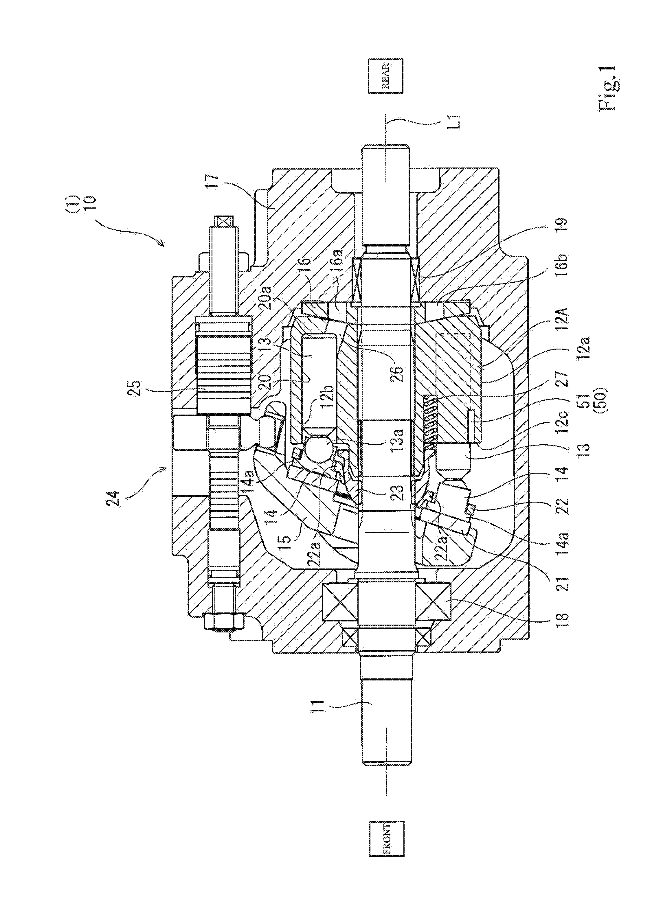
The present invention relates to a cylinder block configured such that pistons inserted in a plurality of cylinder bores formed around a rotating shaft reciprocate and slide in the cylinder bores, and a swash plate type liquid-pressure rotating apparatus including the cylinder block. Various liquid-pressure apparatuses, such as hydraulic motors and hydraulic pumps, are used in industrial machines, such as construction machines. A cylinder block of such liquid-pressure apparatus includes a plurality of cylinder bores into which pistons are inserted through openings formed on a piston insertion end surface of the cylinder block. For example, when the cylinder block rotates, the pistons reciprocate and slide in the cylinder bores. Known as this type of liquid-pressure apparatus is, for example, a swash plate type liquid-pressure apparatus disclosed in PTL 1. The swash plate type liquid-pressure apparatus (hereinafter referred to as a “swash plate type hydraulic rotating apparatus”) of PTL 1 includes a rotating shaft, and a cylinder block is integrally attached to the rotating shaft. Cylinder bores are formed on an end surface of the cylinder block at regular intervals in a circumferential direction, and pistons are inserted in the respective cylinder bores. Shoes are attached to respective end portions of the pistons which portions project from the cylinder bores. The shoes are arranged on a supporting surface of a swash plate arranged in an inclined state. According to the swash plate type hydraulic rotating apparatus configured as above, the pistons reciprocate in the cylinder bores, and this rotates the cylinder block. The pistons reciprocate by the supply of high-pressure operating oil to the cylinder bores, and this rotates the cylinder block. Then, the cylinder block rotates the rotating shaft provided integrally with the cylinder block. To be specific, the swash plate type hydraulic rotating apparatus serves as a hydraulic motor. Further, according to the swash plate type hydraulic rotating apparatus, the pistons reciprocate in the cylinder bores by the rotation of the cylinder block. By making the cylinder block rotate by the rotating shaft, the swash plate type hydraulic rotating apparatus can suck low-pressure operating oil and eject high-pressure operating oil. To be specific, the swash plate type hydraulic rotating apparatus also serves as a hydraulic pump. Known as another conventional art is a liquid-pressure rotating apparatus configured such that detected concave portions detected by an electromagnetic pickup type rotation sensor are formed at a periphery of the cylinder block (see PTL 2). PTL 1: Japanese Patent No. 5444462 PTL 2: Japanese Laid-Open Patent Application Publication No. 2002-267679 The swash plate type hydraulic rotating apparatuses similar in configuration to PTL 1 have been used mainly at low-speed rotation and medium-speed rotation. However, in order to deal with an increase in rotation of driving devices in construction machines and industrial machines, it is desired that the swash plate type hydraulic rotating apparatuses are configured to be usable even at high-speed rotation. When the cylinder block of the swash plate type hydraulic rotating apparatus rotates at high speed, influences of centrifugal force on the pistons and the shoes increase, and unlike the low rotation, the influences of the centrifugal force are unignorable. For example, when the pistons reciprocate in the cylinder bores, the pistons slide on sliding surfaces of the cylinder block, and this generates heat on the sliding surfaces. The amount of heat generated on the sliding surface depends on contact pressure between the cylinder block and the piston. According to conventional low-rotation apparatuses in which the centrifugal force is extremely small, the contact pressure mainly corresponds to pressure of supplied operating oil or ejected operating oil. Therefore, the amount of heat generated on the sliding surface is relatively small. On this account, a clearance though which the operating oil is released is formed between the sliding surface and the piston, and the sliding surface is adequately cooled only by the operating oil leaking through the clearance. However, when the cylinder block rotates at high speed, the influences of the centrifugal force on the contact pressure become more significant than the influences of the oil pressure on the contact pressure. As the rotational speed increases, the contact pressure increases, and the amount of heat generated on the sliding surface also increases. With this, the temperature of the sliding surface increases, and it becomes especially difficult to cool the sliding surface by the operating oil leaking through the clearance. Therefore, the temperature in the vicinity of the opening of the cylinder bore significantly increases. Further, when the centrifugal force increases, the piston is pushed outward, and the width of the clearance at a radially outer side of the cylinder block becomes narrower than the width of the clearance at a radially inner side of the cylinder block. In this case, the operating oil at the narrow clearance at the outer side of the cylinder block hardly flows, and therefore, the operating oil is heated at this position of the clearance. When the operating oil is continuously heated, and the temperature of the operating oil exceeds a transition temperature, lubrication performance of the operating oil deteriorates. By increasing the width of the clearance, the lubrication performance of the operating oil can be prevented from deteriorating. However, since the amount of operating oil leaking through the clearance increases by increasing the width of the clearance, the performance of the swash plate type hydraulic rotating apparatus as a pump or a motor deteriorates, and an increase in pressure of the hydraulic apparatus is limited. In addition, a portion of the cylinder block which portion requires a cooling effect changes depending on the number of cylinder bores of the swash plate type hydraulic rotating apparatus, the rotational frequency, the usages, and the like. The cylinder block which can achieve the cooling effect depending on various swash plate type hydraulic rotating apparatuses is also desired. PTL 2 describes that the concave portions are provided at the periphery of the cylinder block. However, these concave portions just serve as the detected concave portions detected by the rotation sensor and do not cool the cylinder block. An object of the present invention is to provide a cylinder block capable of improving a cooling effect of a sliding surface in accordance with the number of cylinder bores, a rotational frequency, and the like, and a swash plate type liquid-pressure rotating apparatus including the cylinder block. To achieve the above object, a cylinder block according to the present invention includes: a plurality of cylinder bores including respective openings formed on a piston insertion end surface of the cylinder block, pistons being inserted in the respective cylinder bores and being configured to reciprocate and slide in the respective cylinder bores when the cylinder block rotates; and a cooling portion, wherein the cooling portion includes a plurality of cooling holes each formed between the adjacent cylinder bores and extending from the piston insertion end surface in an axial direction of the cylinder block. According to this configuration, when the cylinder block rotates, an ambient cooling liquid (operating oil) that is relatively low in temperature is introduced to the cooling holes of the cooling portion, the cooling holes each being located between the cylinder bores each including a sliding surface on which the piston slides and which becomes high in temperature. The cooling liquid introduced to the cooling holes removes heat from the cylinder block and flows out from the cooling holes. Thus, the cylinder block can be appropriately cooled by the cooling liquid. With this, the cooling performance of the cylinder block can be improved, and the temperature increase of the sliding surface can be suppressed. In addition, since the cooling holes extend from the piston insertion end surface on which the openings of the cylinder bores are located, the temperature increase can be especially suppressed at portions of the sliding surfaces which portions are located close to the piston insertion end surface and most significantly increase in temperature. Each of the cooling holes may be inclined so as to penetrate the cylinder block from the piston insertion end surface toward an outer peripheral surface of the cylinder block. According to this configuration, the cooling liquid flowing into the cooling holes through the piston insertion end surface is discharged to the outer peripheral surface of the cylinder block by centrifugal force generated by the rotation of the cylinder block. Therefore, forced flow of the cooling liquid is generated, and this can improve the cooling effect of the cylinder block. Each of the cooling holes may include: a linear portion extending in parallel with the cylinder bore; and a drain hole portion extending from a position of the linear portion toward an outer peripheral surface of the cylinder block and being open on the outer peripheral surface, the position being located away from the piston insertion end surface. According to this configuration, the cooling liquid flowing into the linear portions of the cooling holes through the piston insertion end surface is discharged through the drain hole portions to the outer peripheral surface of the cylinder block by the centrifugal force generated by the rotation of the cylinder block. Therefore, forced flow of the cooling liquid is generated, and this can improve the cooling effect of the cylinder block. A cylinder block according to the present invention may include: a plurality of cylinder bores including respective openings formed on a piston insertion end surface of the cylinder block, pistons being inserted in the respective cylinder bores and being configured to reciprocate and slide in the respective cylinder bores when the cylinder block rotates; and a cooling portion, wherein the cooling portion may include a plurality of cooling holes each extending in a radial direction from an outer peripheral surface of the cylinder block through a portion between the adjacent cylinder bores. According to this configuration, when the cylinder block rotates, the ambient cooling liquid (operating oil) that is relatively low in temperature is introduced to the cooling holes each extending from the outer peripheral surface of the cylinder block through a portion between the adjacent cylinder bores. The cooling liquid introduced to the cooling holes removes heat from the cylinder block and then flows out from the cooling holes. Thus, the cylinder block can be appropriately cooled by the cooling liquid. A cylinder block according to the present invention may include: a plurality of cylinder bores including respective openings formed on a piston insertion end surface of the cylinder block, pistons being inserted in the respective cylinder bores and being configured to reciprocate and slide in the respective cylinder bores when the cylinder block rotates; and a cooling portion, wherein the cooling portion may include a plurality of cooling holes each extending in a radial direction from an outer peripheral surface of the cylinder block. According to this configuration, when the cylinder block rotates, the ambient cooling liquid (operating oil) that is relatively low in temperature is introduced to the cooling holes each extending from the outer peripheral surface of the cylinder block in the radial direction. The cooling liquid introduced to the cooling holes removes heat from the cylinder block and then flows out from the cooling holes. Thus, the cylinder block can be appropriately cooled by the cooling liquid. The cylinder block may be configured such that: the cylinder bores include respective insert bushings; and each of the cooling holes extends from the outer peripheral surface of the cylinder block to a position of an outer surface of the insert bushing. According to this configuration, the cylinder bores include the insert bushings, and the cooling liquid is introduced to the positions of the insert bushings of the cylinder bores. Thus, the positions close to the cylinder bores which become high in temperature can be appropriately cooled. A cylinder block according to the present invention may include: a plurality of cylinder bores including respective openings formed on a piston insertion end surface of the cylinder block, pistons being inserted in the respective cylinder bores and being configured to reciprocate and slide in the respective cylinder bores when the cylinder block rotates; and a cooling portion, wherein the cooling portion may include: an annular cutout portion formed at an edge portion of the piston insertion end surface of the cylinder block; and a plurality of cooling grooves formed on an outer peripheral surface of the cylinder block so as to extend from the annular cutout portion in an axial direction of the cylinder block. According to this configuration, when the cylinder block rotates, the ambient cooling liquid (operating oil) that is low in temperature is introduced to an outer peripheral portion of the piston insertion end surface of the cylinder block by the annular cutout portion formed at the edge portion of the piston insertion end surface. The cooling liquid is then introduced through the cutout portion to the cooling grooves formed on the outer peripheral surface of the cylinder block and removes heat from the cylinder block. Thus, the cylinder block can be appropriately cooled. A cylinder block according to the present invention may include: a plurality of cylinder bores including respective openings formed on a piston insertion end surface of the cylinder block, pistons being inserted in the respective cylinder bores and being configured to reciprocate and slide in the respective cylinder bores when the cylinder block rotates; and a cooling portion, wherein the cooling portion includes a plurality of cooling grooves each located between the adjacent cylinder bores and formed on an outer peripheral surface of the cylinder block so as to extend from the piston insertion end surface in an axial direction of the cylinder block. According to this configuration, when the cylinder block rotates, the ambient cooling liquid (operating oil) that is relatively low in temperature is introduced to the cooling grooves each extending from the piston insertion end surface of the cylinder block in the axial direction of the cylinder block. The cooling liquid introduced to the cooling grooves removes heat from the cylinder block and flows out from the cooling grooves. Thus, the cylinder block can be appropriately cooled by the cooling liquid. A swash plate type liquid-pressure rotating apparatus according to the present invention is connected to a low-pressure passage through which a low-pressure operating liquid flows and a high-pressure passage through which high-pressure operating oil flows, the swash plate type liquid-pressure rotating apparatus being configured to rotate a cylinder block by supplying the operating liquid through the high-pressure passage to cylinder bores of the cylinder block and discharging the operating liquid from the cylinder bores to the low-pressure passage or the swash plate type liquid-pressure rotating apparatus being configured to suck the operating liquid through the low-pressure passage to the cylinder bores by rotating the cylinder block, compress the operating liquid, and eject the operating liquid to the high-pressure passage, the swash plate type liquid-pressure rotating apparatus including any of the above cylinder blocks. According to this configuration, in the swash plate type liquid-pressure rotating apparatus in which: a clearance is provided between the sliding surface of the cylinder bore and the outer peripheral surface of the piston; and the operating oil leaking through the clearance is utilized as lubricating oil, the temperature increase of the piston sliding surface of the cylinder block can be suppressed. Therefore, the temperature increase of the lubricating oil leaking through the clearance can be suppressed, and this can prevent the transition of the lubricating oil. Thus, the lubrication performance of the lubricating oil can be prevented from deteriorating, and the smooth movement of the piston can be kept. According to the present invention, in the cylinder block configured such that the pistons reciprocate and slide in the cylinder bores, the cooling effect of the cylinder block can be appropriately improved in accordance with conditions, such as the number of cylinder bores, the rotational frequency, and usages. The above object, other objects, features, and advantages of the present invention will be made clear by the following detailed explanation of preferred embodiments with reference to the attached drawings. Hereinafter, embodiments of the present invention will be explained with reference to the drawings. The following embodiments will explain cylinder blocks 12A to 12I in a swash plate type liquid-pressure rotating apparatus 1. In the embodiments below, a left direction in Swash Plate Type Liquid-Pressure Rotating Apparatus The hydraulic motor 10 (swash plate type liquid-pressure rotating apparatus 1) is a high-speed rotation type hydraulic motor including a rotating shaft 11 and configured to be able to rotate the rotating shaft 11 at a high-speed rotational frequency. In addition to the rotating shaft 11, the hydraulic motor 10 includes the cylinder block 12A, a plurality of pistons 13, a plurality of shoes 14, a swash plate 15, and a valve plate 16, and these components are accommodated in a casing 17. The rotating shaft 11 extends in a front-rear direction so as to penetrate the casing 17. The rotating shaft 1 is supported by bearings 18 and 19 at front and rear end portions of the casing 17 so as to be rotatable. An intermediate portion of the rotating shaft 11 is fittingly inserted into the cylinder block 12A. The cylinder block 12A is formed in a substantially cylindrical shape. An axis of the cylinder block 12A coincides with an axis L1 of the rotating shaft 11. The cylinder block 12A is integrally splined to the rotating shaft 11 and rotates integrally with the rotating shaft 11. A plurality of cylinder bores 20 are formed at the cylinder block 12A. The cylinder bores 20 are arranged around the axis L1 at regular intervals in a circumferential direction of the cylinder block 12A (see Each of the pistons 13 is formed in a substantially columnar shape and reciprocates and slides in the front-rear direction while sliding on a sliding surface 12 An outer diameter of the piston 13 is slightly smaller than an inner diameter of the cylinder bore 20. A clearance is formed around the piston 13, i.e., between the piston 13 and the sliding surface 12 The shoe 14 is formed in a substantially bottomed cylindrical shape, and an inner surface of the shoe 14 is formed in a partially spherical shape corresponding to the spherical support portion 13 The swash plate 15 is formed in a substantially circular plate shape. The swash plate 15 is provided in the casing 17 such that an upper portion of the swash plate 15 is inclined rearward. The rotating shaft 11 penetrates a substantially center of the swash plate 15. The swash plate 15 is arranged in front of the cylinder block 12A and includes a supporting plate 21 located close to the cylinder block 12A. The supporting plate 21 is formed in an annular shape, and the shoes 14 are arranged at the supporting plate 21 at regular intervals in the circumferential direction. A retainer plate 22 is provided at the shoes 14 so as to press the shoes 14 against the supporting plate 21. The retainer plate 22 is formed in a substantially annular shape. The rotating shaft 11 is inserted through a center of the retainer plate 22 so as to be rotatable relative to the retainer plate 22. The retainer plate 22 includes attachment holes 22 The upper portion of the swash plate 15 at which the shoes 14 are arranged is coupled to a regulator 24 provided at an upper portion of the casing 17. The regulator 24 includes a plunger 25 configured to be movable in the front-rear direction. The swash plate 15 is coupled to the plunger 25. Therefore, by moving the plunger 25 in the front-rear direction, an inclination angle of the swash plate changes, and this can adjust strokes of the pistons 13. Thus, capacities of oil chambers 20 The cylinder block 12A includes cylinder ports 26 communicating with the oil chambers 20 The valve plate 16 is a plate-shaped member formed in an annular shape and is located between the cylinder block 12A and a rear end portion of the casing 17. The valve plate 16 is fixed to the casing 17 by a pin member (not shown) so as not to be rotatable relative to the casing 17. The rotating shaft 11 is inserted through an inner hole of the valve plate 16. The rotating shaft 11 and the valve plate 16 are rotatable relative to each other. The valve plate 16 located as above includes an inlet port 16 Each of the inlet port 16 According to the hydraulic motor 10 configured as above, the operating oil flowing through the high-pressure passage is sucked through the inlet port 16 In contrast, while the piston 13 is moving from the bottom dead center to the top dead center, the oil chamber 20 When the swash plate type liquid-pressure rotating apparatus 1 serves as a hydraulic pump, the operating oil is sucked from the low-pressure passage into the cylinder bore 20 by the rotation of the cylinder block 12A, and the operating oil compressed in the cylinder bore 20 is ejected to the high-pressure passage. The cylinder block 12A includes a structure configured to cool the cylinder block 12A. The cylinder block 12A of Embodiment 1 shown in the drawings includes a plurality of cooling holes 51 as a cooling portion 50. In addition to the cooling holes 51, examples of the cooling portion 50 include cooling grooves 55 shown in Cylinder Block of Embodiment 1 In the cylinder block 12A of the present embodiment, each of the cooling holes 51 extending from the piston insertion end surface 12 An axial depth H1 of the cooling hole 51 falls within a range of a depth H2 from the piston insertion end surface 12 A diameter D of the cooling hole 51 falls within a range of 5% to 100% of the diameter of the piston 13. When the diameter D of the cooling hole 51 falls within a range of 5% to 100% of the diameter of the piston 13, the cooling holes 51 which can appropriately cool the cylinder block 12A under various conditions can be formed. The diameter D of the cooling hole 51 is set to such a size that the operating oil flowing into the cooling hole 51 from the piston insertion end surface 12 As shown in With this, the cooling performance of the cylinder block 12A can be improved, and the temperature increase of the sliding surface 12 Cylinder Block of Embodiment 2 In the cylinder block 12B of the present embodiment, each of the cooling holes 51 extending from the piston insertion end surface 12 According to the cylinder block 12B of the present embodiment, as with the cylinder block 12A, the operating oil that is relatively low in temperature is introduced to the cooling hole 51 located close to the sliding surface 12 Cylinder Block of Embodiment 3 In the cylinder block 12C of the present embodiment, each of the cooling holes 51 extending from the piston insertion end surface 12 According to the cylinder block 12C of the present embodiment, as with the cylinder block 12A, the operating oil that is relatively low in temperature is introduced to the cooling hole 51 located close to the sliding surface 12 Cylinder Block of Embodiment 4 In the cylinder block 12D of the present embodiment, each of the cooling holes 51 extending from the piston insertion end surface 12 According to the cylinder block 12D of the present embodiment, as with the cylinder block 12A, the operating oil that is relatively low in temperature is introduced to the cooling hole 51 located close to the sliding surface 12 Cylinder Block of Embodiment 5 The cylinder block 12E of the present embodiment includes the cooling holes 51 each extending from the outer peripheral surface 12 The present embodiment explains a case where the number of cooling holes 51 is one in the direction along the axis L1 of the cylinder block 12E. However, the cooling holes 51 may be additionally provided at positions required to be cooled in the direction along the axis L1, and the number of cooling holes 51 is not limited to the example shown in the drawings. According to the cylinder block 12E of the present embodiment, by the cooling hole 51 extending between the adjacent cylinder bores 20, the operating oil that is relatively low in temperature and introduced to the cooling hole 51 can appropriately cool a position close to the sliding surface 12 Cylinder Block of Embodiment 6 The cylinder block 12F of the present embodiment includes the cooling holes 51 each extending from the outer peripheral surface 12 According to the cylinder block 12F of the present embodiment, the operating oil that is relatively low in temperature and introduced to the cooling hole 51 can appropriately cool a position close to the sliding surface 12 Cylinder Block of Embodiment 7 In the cylinder block 12G of the present embodiment, an annular cutout portion 56 is provided at an edge portion of the piston insertion end surface 12 The cooling grooves 55 are provided on the outer peripheral surface 12 The axial depth H1 of the cooling groove 55 falls within a range of the depth H2 from the piston insertion end surface 12 The cooling grooves 55 of the present embodiment are provided on the outer peripheral surface 12 Cylinder Block of Embodiment 8 As with The cooling grooves 55 are provided so as to extend from the cutout portion 56 in an axial direction of the cylinder block 12H. Each of the cooling grooves 55 of the present embodiment is provided at a radially outer side of the cylinder bore 20 so as to extend from the cutout portion 56 in the direction along the axis L1 of the cylinder block 12H. The cooling groove 55 can also be provided in a range from the piston insertion end surface 12 According to the cylinder block 12H of the present embodiment, as with the cylinder block 12G the operating oil that is relatively low in temperature is introduced to the cooling grooves 55 of the outer peripheral surface 12 Cylinder Block of Embodiment 9 The cylinder block 12I of the present embodiment includes the cooling grooves 55 extending from the piston insertion end surface 12 According to the cylinder block 12I of the present embodiment, by the cooling groove 55 provided between the adjacent cylinder bores 20, the operating oil that is relatively low in temperature is introduced to a position close to the sliding surface 12 As above, the cylinder blocks 12A to 12I can be adopted in accordance with specifications (such as the number of cylinder bores 20 of the hydraulic motor 10 (swash plate type liquid-pressure rotating apparatus 1) and the rotational frequency), conditions (such as usages), and the like. With this, the cylinder blocks 12A to 12I can be appropriately cooled. By appropriately cooling the cylinder blocks 12A to 12I, the temperature increase of the operating oil can be suppressed, and the lubrication performance of the operating oil can be prevented from deteriorating. Therefore, the swash plate type liquid-pressure rotating apparatus 1 and the like can be systematically and stably operated. The above embodiments have explained cases where the hydraulic motor 10 is used as the swash plate type liquid-pressure rotating apparatus 1. However, the swash plate type liquid-pressure rotating apparatus 1 can be utilized as the other liquid-pressure apparatuses, such as hydraulic pumps. The liquid-pressure apparatus is not limited to the above embodiments. Each of the above embodiments shows one example, and the embodiments may be combined with each other. Various modifications may be made within the scope of the present invention, and the present invention is not limited to the above embodiments. From the foregoing explanation, many modifications and other embodiments of the present invention are obvious to one skilled in the art. Therefore, the foregoing explanation should be interpreted only as an example and is provided for the purpose of teaching the best mode for carrying out the present invention to one skilled in the art. The structures and/or functional details may be substantially modified within the scope of the present invention. A cylinder block includes: a plurality of cylinder bores including respective openings formed on a piston insertion end surface of the cylinder block, pistons being inserted in the respective cylinder bores and being configured to reciprocate and slide in the respective cylinder bores when the cylinder block rotates; and a cooling portion, wherein the cooling portion includes a plurality of cooling holes each formed between the adjacent cylinder bores and extending from the piston insertion end surface in an axial direction of the cylinder block. 1. A cylinder block comprising:
a plurality of cylinder bores including respective openings formed on a piston insertion end surface of the cylinder block, pistons being inserted in the respective cylinder bores and being configured to reciprocate and slide in the respective cylinder bores when the cylinder block rotates; and a cooling portion, wherein the cooling portion includes a plurality of cooling holes each formed between the adjacent cylinder bores and extending from the piston insertion end surface in an axial direction of the cylinder block. 2. The cylinder block according to 3. The cylinder block according to a linear portion extending in parallel with the cylinder bore; and a drain hole portion extending from a position of the linear portion toward an outer peripheral surface of the cylinder block and being open on the outer peripheral surface, the position being located away from the piston insertion end surface. 4. A cylinder block comprising:
a plurality of cylinder bores including respective openings formed on a piston insertion end surface of the cylinder block, pistons being inserted in the respective cylinder bores and being configured to reciprocate and slide in the respective cylinder bores when the cylinder block rotates; and a cooling portion, wherein the cooling portion includes a plurality of cooling holes each extending in a radial direction from an outer peripheral surface of the cylinder block through a portion between the adjacent cylinder bores. 5. A cylinder block comprising:
a plurality of cylinder bores including respective openings formed on a piston insertion end surface of the cylinder block, pistons being inserted in the respective cylinder bores and being configured to reciprocate and slide in the respective cylinder bores when the cylinder block rotates; and a cooling portion, wherein the cooling portion includes a plurality of cooling holes each extending in a radial direction from an outer peripheral surface of the cylinder block. 6. The cylinder block according to the cylinder bores include respective insert bushings; and each of the cooling holes extends from the outer peripheral surface of the cylinder block to a position of an outer surface of the insert bushing. 7. A cylinder block comprising:
a plurality of cylinder bores including respective openings formed on a piston insertion end surface of the cylinder block, pistons being inserted in the respective cylinder bores and being configured to reciprocate and slide in the respective cylinder bores when the cylinder block rotates; and a cooling portion, wherein the cooling portion includes: an annular cutout portion formed at an edge portion of the piston insertion end surface of the cylinder block; and a plurality of cooling grooves formed on an outer peripheral surface of the cylinder block so as to extend from the annular cutout portion in an axial direction of the cylinder block. 8. A cylinder block comprising:
a plurality of cylinder bores including respective openings formed on a piston insertion end surface of the cylinder block, pistons being inserted in the respective cylinder bores and being configured to reciprocate and slide in the respective cylinder bores when the cylinder block rotates; and a cooling portion, wherein the cooling portion includes a plurality of cooling grooves each located between the adjacent cylinder bores and formed on an outer peripheral surface of the cylinder block so as to extend from the piston insertion end surface in an axial direction of the cylinder block. 9. A swash plate type liquid-pressure rotating apparatus connected to a low-pressure passage through which a low-pressure operating liquid flows and a high-pressure passage through which high-pressure operating oil flows,
the swash plate type liquid-pressure rotating apparatus being configured to rotate a cylinder block by supplying the operating liquid through the high-pressure passage to cylinder bores of the cylinder block and discharging the operating liquid from the cylinder bores to the low-pressure passage or the swash plate type liquid-pressure rotating apparatus being configured to suck the operating liquid through the low-pressure passage to the cylinder bores by rotating the cylinder block, compress the operating liquid, and eject the operating liquid to the high-pressure passage, the swash plate type liquid-pressure rotating apparatus comprising the cylinder block according to 10. A swash plate type liquid-pressure rotating apparatus connected to a low-pressure passage through which a low-pressure operating liquid flows and a high-pressure passage through which high-pressure operating oil flows,
the swash plate type liquid-pressure rotating apparatus being configured to rotate a cylinder block by supplying the operating liquid through the high-pressure passage to cylinder bores of the cylinder block and discharging the operating liquid from the cylinder bores to the low-pressure passage or the swash plate type liquid-pressure rotating apparatus being configured to suck the operating liquid through the low-pressure passage to the cylinder bores by rotating the cylinder block, compress the operating liquid, and eject the operating liquid to the high-pressure passage, the swash plate type liquid-pressure rotating apparatus comprising the cylinder block according to 11. A swash plate type liquid-pressure rotating apparatus connected to a low-pressure passage through which a low-pressure operating liquid flows and a high-pressure passage through which high-pressure operating oil flows,
the swash plate type liquid-pressure rotating apparatus being configured to rotate a cylinder block by supplying the operating liquid through the high-pressure passage to cylinder bores of the cylinder block and discharging the operating liquid from the cylinder bores to the low-pressure passage or the swash plate type liquid-pressure rotating apparatus being configured to suck the operating liquid through the low-pressure passage to the cylinder bores by rotating the cylinder block, compress the operating liquid, and eject the operating liquid to the high-pressure passage, the swash plate type liquid-pressure rotating apparatus comprising the cylinder block according to 12. A swash plate type liquid-pressure rotating apparatus connected to a low-pressure passage through which a low-pressure operating liquid flows and a high-pressure passage through which high-pressure operating oil flows,
the swash plate type liquid-pressure rotating apparatus being configured to rotate a cylinder block by supplying the operating liquid through the high-pressure passage to cylinder bores of the cylinder block and discharging the operating liquid from the cylinder bores to the low-pressure passage or the swash plate type liquid-pressure rotating apparatus being configured to suck the operating liquid through the low-pressure passage to the cylinder bores by rotating the cylinder block, compress the operating liquid, and eject the operating liquid to the high-pressure passage, the swash plate type liquid-pressure rotating apparatus comprising the cylinder block according to 13. A swash plate type liquid-pressure rotating apparatus connected to a low-pressure passage through which a low-pressure operating liquid flows and a high-pressure passage through which high-pressure operating oil flows,
the swash plate type liquid-pressure rotating apparatus being configured to rotate a cylinder block by supplying the operating liquid through the high-pressure passage to cylinder bores of the cylinder block and discharging the operating liquid from the cylinder bores to the low-pressure passage or the swash plate type liquid-pressure rotating apparatus being configured to suck the operating liquid through the low-pressure passage to the cylinder bores by rotating the cylinder block, compress the operating liquid, and eject the operating liquid to the high-pressure passage, the swash plate type liquid-pressure rotating apparatus comprising the cylinder block according to 14. A swash plate type liquid-pressure rotating apparatus connected to a low-pressure passage through which a low-pressure operating liquid flows and a high-pressure passage through which high-pressure operating oil flows,
the swash plate type liquid-pressure rotating apparatus being configured to rotate a cylinder block by supplying the operating liquid through the high-pressure passage to cylinder bores of the cylinder block and discharging the operating liquid from the cylinder bores to the low-pressure passage or the swash plate type liquid-pressure rotating apparatus being configured to suck the operating liquid through the low-pressure passage to the cylinder bores by rotating the cylinder block, compress the operating liquid, and eject the operating liquid to the high-pressure passage, the swash plate type liquid-pressure rotating apparatus comprising the cylinder block according to 15. A swash plate type liquid-pressure rotating apparatus connected to a low-pressure passage through which a low-pressure operating liquid flows and a high-pressure passage through which high-pressure operating oil flows,
the swash plate type liquid-pressure rotating apparatus being configured to rotate a cylinder block by supplying the operating liquid through the high-pressure passage to cylinder bores of the cylinder block and discharging the operating liquid from the cylinder bores to the low-pressure passage or the swash plate type liquid-pressure rotating apparatus being configured to suck the operating liquid through the low-pressure passage to the cylinder bores by rotating the cylinder block, compress the operating liquid, and eject the operating liquid to the high-pressure passage, the swash plate type liquid-pressure rotating apparatus comprising the cylinder block according to 16. A swash plate type liquid-pressure rotating apparatus connected to a low-pressure passage through which a low-pressure operating liquid flows and a high-pressure passage through which high-pressure operating oil flows,
the swash plate type liquid-pressure rotating apparatus being configured to rotate a cylinder block by supplying the operating liquid through the high-pressure passage to cylinder bores of the cylinder block and discharging the operating liquid from the cylinder bores to the low-pressure passage or the swash plate type liquid-pressure rotating apparatus being configured to suck the operating liquid through the low-pressure passage to the cylinder bores by rotating the cylinder block, compress the operating liquid, and eject the operating liquid to the high-pressure passage, the swash plate type liquid-pressure rotating apparatus comprising the cylinder block according to TECHNICAL FIELD
BACKGROUND ART
CITATION LIST
Patent Literature
SUMMARY OF INVENTION
Technical Problem
Solution to Problem
Advantageous Effects of Invention
BRIEF DESCRIPTION OF DRAWINGS
DESCRIPTION OF EMBODIMENTS
CONCLUSION
REFERENCE SIGNS LIST