Apparatus and Methods for Growing Organic Matter
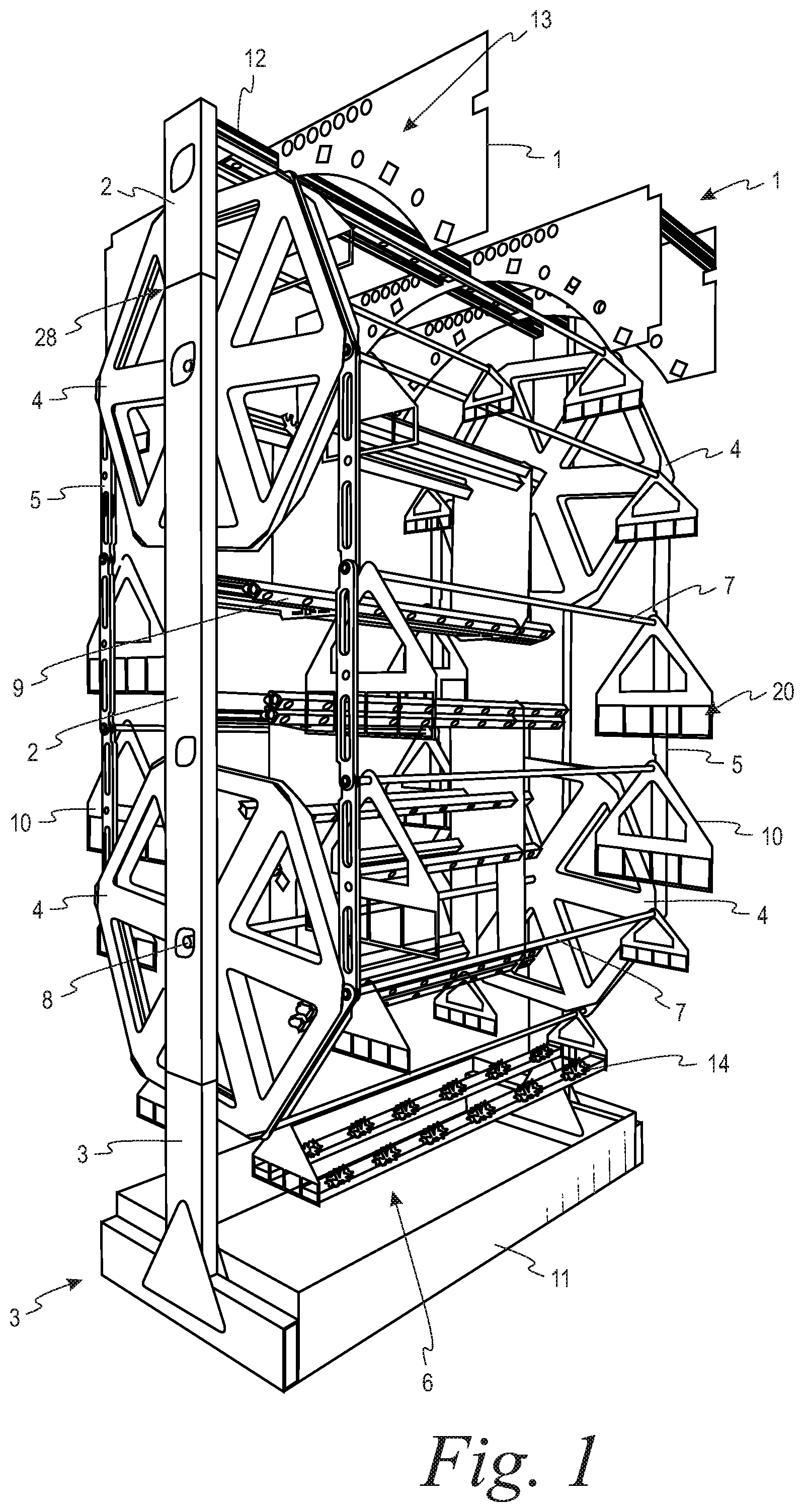
The present invention relates generally to agricultural growing apparatuses and methods. More specifically the present invention relates to a dynamic, modular, rotating hydroponic apparatus and methods related to the apparatus' use and/or function. Hydroponic methods used to irrigate and/or grow plants are well known. However, problems abound with known prior art systems. For example, there is significant cost associated with hydroponically producing plants. Oftentimes, hydroponic growers need “hothouses” to adequately nourish their plants; however, for an individual farmer, constructing such a “hothouse” to grow more than a few plants at a time is both challenging to build and cost prohibitive. Given rising land-costs and transportation-related considerations, among other things, many farmers cannot generate a minimal commercial yield. Thus, many individual farmers have looked elsewhere to generate revenue. Additionally, other deficiencies within the prior art exist. Both hydroponic and aquaponic farmers continue to struggle with replenishing growth media in a consistent manner. Furthermore, because repositioning existing apparatuses is difficult, plants often do not receive optimal, growth-sustaining amounts of light. Moreover, existing apparatuses inadequately address the farmer's ability to create a flexible or dynamic system; the hydroponic growing devices on the market are rigid, unable to be easily transported, and cannot adapt to different plant loads or configurations, including over the time span of a growing season. A further advantage of this invention is that it allows for the growing and harvesting of organic matter in close proximity to the relevant market, such as restaurants or grocery stores. Accordingly, there is a need for new type of hydroponic growing apparatus, and methods, as described herein. To meet the needs described above and others, the present disclosure provides an apparatus for growing organic matter including: at least one payload carrying station, which holds organic matter, connected via at least one tubing shaft to a plurality of links configured to form a continuous link belt. The link belt interacts with and/or engages with at least two sprockets. The sprockets are attached to a support frame. The sprockets are actuated by any conventional mechanical device capable of rotating the link belt. Moreover, a further embodiment of the apparatus for growing organic matter provides for the support frame to be modular allowing for the increase in height and therefore capacity of the apparatus. Furthermore, an additional embodiment of the apparatus for growing organic matter may comprise a device capable of lifting and lowering the support frame. An embodiment of this invention may also comprise at least one method for irrigating and growing organic matter by assembling and/or using the apparatus for growing organic matter. Additional objects, advantages and novel features of the examples will be set forth, in part, in the description which follows and will become apparent to those skilled in the art upon examination of the following description and the accompanying drawings or may be learned by production or operation of the examples. The objects and advantages of the concepts may be realized and attained by means of the methodologies, instrumentalities and combinations particularly pointed out in the appended claims. To meet the needs described above and others, the present invention provides a modular system for both hydroponically irrigating and growing organic matter, as well as at least one method for irrigating and growing organic matter. In addition to hydroponics, the present invention applies to aquaponics, aeroponics, vermiponics and any other process for irrigating, nurturing and growing organic matter. One embodiment of the invention may comprise a modular vertical support frame 2, which may be made of tubing, including but not limited to, circular, square or rectangular tubing. Modular may refer to the support frame's ability to couple to other components. For example, as shown in Because the modular vertical support frames 2 may be configured to couple together or detachably connect to each other, the frame 2 structure is dynamic and may be changed and/or configured by the user. The frame 2 may comprise at least one post or a plurality of detachably connected posts, depending on the user's preference. As shown in Furthermore, in a preferred embodiment, the modular vertical support frames 2 may be supported by two attached horizontal base 3 frame pieces. The base 3 frame pieces may comprise circular, square or rectangular tubing or any other suitable form. This tubing may be identical to the type of tubing used in the vertical support frame 2, and at least one base 3 frame piece may be oriented and affixed perpendicularly against another base 3 frame piece, as shown in As shown in The link-belt 5 may comprise at least one channel, tube and/or trough. The channel, tube, and/or trough may be oriented parallel to the ground. The link-belt 5 may further comprise at least one channel, tube or trough. The channels, tubes and/or troughs may comprise sides, bottoms and ends. The channels, tubes and/or troughs may be irrigated by partial or full submersion within a fluid, spray, misting, or by any other appropriate irrigation method. Moreover, as shown for example in Additionally, in a preferred embodiment, the link-belt 5 may be comprised of at least one link with at least one opening at its ends, which may house at least one bearing. Any appropriate type of bearing may be used. At least one link may be configured to connect with at least a second link by any appropriate method including, but not limited to, being strung together with a tubing shaft 7. The tubing shaft 7 may be configured to support a link-belt 5 assembly at both ends. This configuration may form a dual link-belt 5 and tubing shaft 7 assembly. As shown in In a preferred embodiment, the sprocket 4 may have six teeth 23; in other embodiments any appropriate number of teeth 23 may be used. The six-toothed 23 sprocket 4 may be referred to as a hex-sprocket. The sprocket 4 may be modular. Each sprocket 4 may be an assembly, comprising universal side plates, hub and teeth 23. Each tooth 23 may be rotated at least once to prevent wear or once worn over time. The rotation may be at an angle of 120-degrees or another appropriate angle of the user's choosing. The teeth 23 may be configured to connect to a six-sided plate, which may be connected to another six-sided plate and via at least one through-shaft 8 to the frame 2. The plate may have pockets at each of its vertices; each pocket may be configured to accept a tooth 23. As shown in Certain embodiments of the apparatus may comprise aluminum, stainless steel, and/or plastics. Additionally, any other appropriate materials may be used to construct the apparatus. In a preferred embodiment, the apparatus is comprised of aluminum plate and tubing. When necessary, the aluminum may be hardened, hard-coat anodized, and/or Teflon® treated, to resist corrosion, wear and tear and/or to reduce friction or to comply with various sanitary and/or hygienic concerns or requirements. Furthermore, in certain embodiments, the tubing shafts 7, the link-belt 5 and the side-support plates 10 may be designed to accept at least one split bearing. The split bearing may be comprised of a polymer including but not limited to: Delrin®, nylon or ultra-high-molecular-weight polyethylene (UHMW) to allow for rotational movement about each respective horizontal axis of the tubing shaft 7. The split bearings may be further separated by washers, thrust bearings or spacers. The washers, thrust bearings and/or spacers may be restrained as necessary by additional objects including but not limited to retaining rings. The retaining rings may contain an external split, a single turn spiral, and/or be comprised of stainless steel. In addition, in certain embodiments, the payload may be suspended vertically and inward of the belt-link 5 assembly with at least two side-support plates 10. As shown in In a preferred embodiment, as illustrated in Additionally, in one embodiment shown in In one embodiment, each through shaft 8, sprocket 4, and flanged bearing assembly 18 may be mounted to a two-post vertical frame 2 at a distance of a user's choosing to form the vertical spacing desired. The through shaft 8, sprocket 4, and flanged bearing assembly 18 may be mounted through openings in the side walls, affixed with nuts and bolts, and supported by flanged bearings. This arrangement may allow for rotational movement about the horizontal axis. In addition to nuts, bolts and flanged bearings, other appropriate methods may be used to affix and support the through shaft 8, sprocket 4, and/or flanged bearing assembly 18. In some embodiments, the link-belt 5 and payload carrying station 6 may be actuated by mechanical devices including but not limited to a shaft-mount gear-motor incorporating direct drive of the upper drive shaft comprising a primary mover 24, such as, for example, an electric motor, gear reducer, and variable frequency drive. This actuation system may provide the apparatus the ability to reduce its speed or completely stop, in addition to giving the apparatus variable speed, bi-directional control, including forward and reverse capability. The actuation system may also allow the apparatus to be controlled by remote input. Finally, the primary mover 24 may comprise, or be integrated with existing building and/or plant infrastructure, a computer or micro-computer, and may be networked for local or remote monitoring and operations. Furthermore, as shown in Additionally, in certain embodiments, supplemental and additional tank modules may be added as desired. The supplemental tank modules may be used to increase the amount of fluid that may be contained by the apparatus. Additionally, the supplemental tank modules may be used to house fluid transferred from the main tank or provide for varied fluids, such as feedstocks. Fluid transfer may be actuated by mechanical devices, including but not limited to pumps or valves, or by gravity. Pumps and valves may control the flow of liquid bi-directionally, either via manual inputs or through electromechanical devices including, but not limited to valves, solenoids, and/programmable logic controllers (PLCs). Additionally, computer controlled programs, software programs, or any other control mechanisms may be used to control tank supply and/or the fluid management system. Furthermore, the main tank 11 may be configured to detachably connect to at least one supplemental tank. Supplemental tanks may be inserted into the main tank or stacked above the main tank 11 as desired. A support frame may be detachably connected to the supplemental tank. The tanks 11 may be configured to accommodate detachable objects for spraying, blowing or misting the payload. The spray, misting or blowing systems may perform operations, including but not limited to supplying gases, washing, and fluid applications. The detachable devices may be connected at the tank 11 or the vertical support frame 2. A blowing system may be configured to release carbon dioxide or other appropriate gasses in a controlled manner. With regard to lighting, in addition to natural light, the apparatus may be configured to accommodate at least one light bar 9 including but not limited to Philips® 48- and 60-inch overall length (“OAL”) LED-GP series production modules. A light bar 9 may also include incandescent, halogen, fluorescent or LED bulbs and/or lighting, or any other appropriate lighting device known to those skilled in the art. A light bar 9 may be attached at various locations along the top portion of the apparatus, above the highest link-belt 5, e.g., the “crown” 1 of the apparatus. At least one light bar 9 may be attached to at least one horizontal support 12. The horizontal support 12 may reinforce the vertical support frames 2. Furthermore, at least one light bar 9 may be attached to the smaller open areas of the structure—predominately the area available between the shaft-sprocket 4 assemblies—which does not interfere with the sprocket assemblies 4 or the payload carrying station 6. In one embodiment, lighting support plates or brackets, step-up plates and/or step-down plates are used to attach at least one light bar 9 to the structure. At least one horizontal support 12 may be configured to connect to at least one lighting support bracket. The lighting support brackets, including the step-up and/or step-down plates, may be free-floating on the horizontal support 12 and comprise pockets. The pockets may be of various sizes and angles. The lighting support brackets also may guide, support, align and retain the light-bars, including ancillary cabling, spray bars and various supply lines. Moreover, at least one step-up/step-down support bracket may allow the installable reach and number of lights to be extended; at least one shorter light bar 9 may be included to accommodate the requisite clearance from the payload carrying stations 6, through shafts 8 and/or sprockets 4. In certain embodiments, and while the apparatus is stationary, the light bars 9 may be increased or decreased in number and/or fixed in position. Furthermore, the payload may rotate in a loop and may also oscillate, due to the sprocket 4 and link-belt 5 design described herein. This may provide a more uniform light distribution and also misting distribution for the payload, among other benefits. Power for the artificial lighting may be supplied by a cord, plug or by any other appropriate method. In certain embodiments, the power source may be connected to or integral with one of the two-post vertical support frames 2; this connection may be placed at the inside of the frames, various tubes and/or shafts. At least one frame 2 may comprise ingress and egress intrusion along the sides and/or outside of the frame 2. The cord may travel from at least one intrusion and detachably connect to at least one light bar 9, providing power to the light bars 9. In a preferred embodiment, the light bar 9 may comprise LED lights. The LEDs may be powered by an electrical cord or any other appropriate power supply, and may be arranged in a horizontal or vertical configuration. This power supply configuration may allow for year-round plant, aquatic and crop production in any environment, topography, soil or climate, including but not limited to indoor environments. In some embodiments, electricity and other supply lines may be routed from a ceiling or rafters, to the top of the apparatus and then toward the bottom—down to a lower vertical rail—where it may be further distributed, both vertically and horizontally, across the apparatus. In addition, further appropriate power and signal distribution devices including but not limited to plugs, connectors and sockets, may be detachably placed along the apparatus for safety and mobility. Other objects, including but not limited to tanks 11, may be housed, attached or routed similarly. A routing system may provide water, nutrients, and various air or gasses to the payload. One embodiment of the routing system may include at least one cable tray, at least one slotted wire duct, at least one hose, at least one cable duct routed on and/or through at least one support frame 2, at least one base 3 piece, and/or other support infrastructure, such as the horizontal support 12, light bar 9 and outrigger 37. Finally, transfer supply lines and drainage may be centralized and concentrated at one end and more commonly opposite of the power side of the apparatus. Certain embodiments of the apparatus may be designed with standard mounts to accept at least one adaptive hard-mounting point 21 at the horizontal and vertical frame 2 structure. The hard-mounting point 21 may be configured to allow different attachments to be added or removed. As shown in In some embodiments, an aquaculture tank 11 may be attached to the bottom of the apparatus. The tank 11 may grow and house aquatic plants and animals. The main tank 11 may be configured to accommodate tank extensions. The aquatic culture may comprise freshwater plants and fish varieties, including but not limited to: Watercress, Tilapia, Perch, Trout, Barramundi, Prawns and/or Crayfish. As shown in Certain embodiments of this invention may comprise a plurality of payload carrying stations 6 linked together to form a continuous link-belt 5. The payload carrying stations 6 may hold organic matter, including but not limited to plants 14. The link-belt 5 may be oriented vertically, while the payload carrying stations 6 may be oriented horizontally. The link-belt 5 may be in contact with, connected to and/or engaged with at least one drive sprocket 4 and at least one idler sprocket 4. The sprockets 4 may be attached to at least one through shaft 8 and to at least one support frame 2. The support frame 2 may comprise at least two posts and may be modular. Moreover, a tank 11 may be attached to the support frame 2. The tank 11 may hold liquid, with the liquid comprising nutrients for nourishing the aquatic plants, aquatic animals, and/or the payload, including but not limited to plants 14. Furthermore, a motorized drive mechanism, described here as the prime mover 24, including but not limited to an engine to rotate the link-belt 5. The drive mechanism may allow the belt to move at various speeds, and may stop and start the link-belt 5 when directed. Additionally, when moving, the link-belt 5 may transport at least one payload carrying station 6 through the tank 11, wherein the payload may be fully or partially submerged in the liquid. Certain embodiments of this invention may employ a liquid mister. The mister may be attached to the vertical support frame 2 and/or to one or more horizontal supports 12 and connected to the liquid supply. When a payload carrying stations 6 passes through the mister's line of spray, any plants 14 within the payload carrying stations 6 may be hydrated and nourished. Moreover, payload carrying stations 6 may be added to the link-belt 5 as needed, making the system adjustable and dynamic. Furthermore, an embodiment may comprise devices configured to raise and lower the apparatus. A hydraulic or mechanical motor may propel the apparatus in an upward or downward direction. Moreover, the apparatus may be supported by ball bearings 33, allowing the system to achieve multi-directional motion. The ball bearings 33 may make contact with the ground or floor. Additionally, jacking bolts or separate leveling cylinders in addition to the ball bearing 33 may connect to the ground or floor. An embodiment of the invention also may comprise at least one method for irrigating and growing organic matter, including but not limited to plants 14. One preferred method may comprise at least one or more of the following: assembling the apparatus as described above; placing growth medium, including but not limited to soil or soil substitutes in at least one tray, trough or sleeve; placing organic material, including but not limited to plants 14 in at least one payload carrying station 6; placing irrigating liquid, including but not limited to water, in the main tank 11 and any supplemental tanks; illuminating at least one light bar 9 by connecting it with a power source; actuating the apparatus, including the link-belt 5 assembly, by plugging a power cord into an electrical outlet; and misting the organic material using a mister. The invention also may comprise at least one method for assembling the apparatus. One method may comprise detachably connecting one or more of the following: at least one crown piece 1 at the top of at least one support frame 2 piece; at least one base 3 frame piece to the bottom of at least one support frame 2 piece; at least one sprocket 4 via a through shaft 8 to at least one bearing assembly 18, to at least one support frame 2 piece; at least one tray, one channel, one tube, one trough, one sleeve or one other payload carrying object to at least one side support plate 10, to at least one tubing shaft 7 to form a payload carrying station 6; at least one link-belt 5 assembly to at least one sprocket 4; at least one light bar 9 to at least one horizontal support 12; at least one horizontal support 12 to at least one support frame 2 piece; an outrigger 37 to at least one support frame 2 piece, or base 3 frame piece; at least one tank 11 to at least one base 3 frame piece; a mobility system 29 to at least one base 3 frame piece; and may house a power system, including but not limited to at least one power cord to: at least one light bar 9, the outrigger 37, and at least one prime mover or motor driving the apparatus' through shaft 8 and sprocket 4 and link-belt 5 assembly. While a preferred embodiment of the present invention has been disclosed and described herein for purposes of illustration and not for purposes of limitation, it will be understood by those skilled in the art that various changes in form and detail may be made therein without departing from the spirit and scope of the invention. Overall shape and design features are not limited by characteristics of the assembly, or components described in the descriptions, summary and abstract. Overall method steps are not limited by the steps described in the descriptions, summary and abstract. The present invention relates generally to agricultural growing apparatuses and methods. More specifically the present invention relates to a dynamic, modular, rotating apparatus, and methods related to the apparatus' use and/or function. 1. An apparatus for growing organic matter comprising:
a first plurality of links wherein at least one link is configured to connect with at least a second link to form a continuous first link belt; a second plurality of links wherein at least one link is configured to connect with a second link to form a continuous second link belt; at least one tubing shaft connected to said first link belt and second link belt; at least one payload carrying station configured to hold a payload, wherein said station is connected to said tubing shaft; a plurality of support frames comprised of at least one first support frame and at least one second support frame; wherein at least two first sprockets are connected to said first support frame; at least two second sprockets are connected to said second support frame; said first link belt is configured to engage and rotate said first sprockets; said second link belt is configured to engage and rotate said second sprockets; and at least one of said first or second sprocket is actuated by a device to rotate said first or second link belts. 2. The apparatus for growing organic matter of 3. The apparatus for growing organic matter of 4. The apparatus for growing organic matter of 5. The apparatus for growing organic matter of 6. The apparatus for growing organic matter of 7. The apparatus for growing organic matter of 8. The apparatus for growing organic matter of 9. The apparatus for growing organic matter of 10. The apparatus for growing organic matter of 11. The apparatus for growing organic matter of 12. The apparatus for growing organic matter of 13. The apparatus for growing organic matter of 14. The apparatus for growing organic matter of 15. The apparatus for growing organic matter of 16. An apparatus for growing organic matter comprising:
a first plurality of links wherein at least one link is configured to connect with at least a second link to form a continuous first link belt; a second plurality of links wherein at least one link is configured to connect with a second link to form a continuous second link belt; at least one tubing shaft connected to said first link belt and second link belt; at least one payload carrying station configured to hold a payload, wherein said station is connected to said tubing shaft; a plurality of support frames comprised of at least one first support frame and at least one second support frame; wherein at least two first sprockets are connected to said first support frame; at least two second sprockets are connected to said second support frame; said first link belt is connected to said first sprockets; said second link belt is connected to said second sprockets; at least one of said first or second sprockets is actuated by a device to rotate said first or second link belts; at least one tubing beam, wherein said tubing beam is comprised of at least two legs; a plurality of base frames comprised of at least one first base frame and one second base frame, wherein said first and second base frames are attached to said tubing beam; at least one split between said support frames and said base frame; and said support frame is capable of being raised or lowered at said split. 17. The apparatus for growing organic matter of 18. The apparatus for growing organic matter of 19. The apparatus for growing organic matter of 20. The apparatus for growing organic matter of 21. An apparatus for growing organic matter comprising:
a first plurality of links wherein at least one link is configured to connect with at least a second link to form a continuous first link belt; a second plurality of links wherein at least one link is configured to connect with a second link to form a continuous second link belt; at least one tubing shaft connected to said first link belt and said second link belt; at least one payload carrying station configured to hold a payload, wherein said station is connected to said tubing shaft; a plurality of first support frames; a plurality of second support frames; wherein at least one of said first support frames is configured to attach to at least one of said second support frames and wherein at least two first sprockets are connected to said first and second support frames; a plurality of third support frames; a plurality of fourth support frames; wherein said third support frame is configured to attach to said fourth support frame and wherein at least two second sprockets are connected to said third and fourth support frames; said first link belt is connected to said first sprockets; said second link belt is connected to said second sprockets; and at least one of said first or second sprockets is actuated by a device to rotate said first or second link belts. 22. The apparatus for growing organic matter of 23. The apparatus for growing organic matter of 24. The apparatus for growing organic matter of 25. The apparatus for growing organic matter of 26. An method for growing organic matter comprising:
connecting a first plurality of links wherein at least one link is configured to connect with at least a second link to form a continuous first link belt; connecting a second plurality of links wherein at least one link is configured to connect with a second link to form a continuous second link belt; connecting at least one tubing shaft to said first link belt and second link belt; configuring at least one payload carrying station to hold a payload; connecting said station to said tubing shaft; connecting at least two first sprockets to at least one first support frame; connecting at least two second sprockets to at least one second support frame; connecting at least two second sprockets to said second support frame; connecting said first link belt to said first sprockets; connecting said second link belt to said second sprockets; and actuating said at least one of said first or second sprockets using a device to rotate at least one said first or second link belts.BACKGROUND OF THE INVENTION
BRIEF SUMMARY OF THE INVENTION
BRIEF DESCRIPTION OF THE DRAWINGS
DETAILED DESCRIPTION OF THE INVENTION