Advanced hybrid tank, Advanced PV cooling panel, Advanced thermal focusing panel
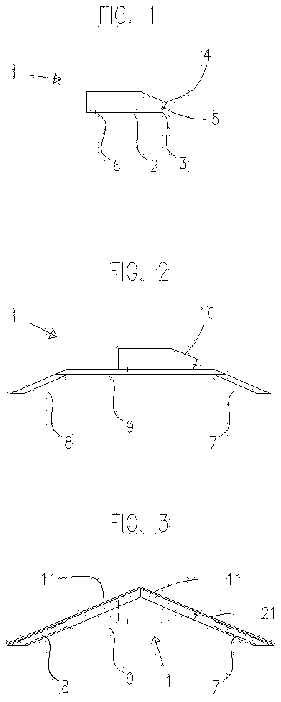
U.S. Ser. No. 15/426,010 with a filing date of Feb. 6, 2017. Not applicable. Not applicable. This invention relates to solar energy panels and tanks for thermal transfer. The invention is shaped to allow coupling with an upper covering and to maximize thermal syphoning of a heat collector element, while containing a liquid to perform thermal transfer. A thermal syphoning tank is placed at a higher elevation than a heat collector element to generate the effect of thermal syphoning. A standard thermal syphoning tank is typically placed on top of a roof to collect solar radiation. This type of tank is typically cylindrical and placed exterior of the roof's upper covering, which can add stress to an existing roof and may not be esthetically pleasing. A heat collector element is typically tilted toward the equator to collect solar heat using a liquid to transfer heat to a tank. This stored heat is typically utilized by passing water through a coiled pipe in the tank, as a closed system, to allow water in the coiled pipe to absorb heat from the heated liquid in the tank, and provide heated water to showers or sinks. This type of system only heats a volume of water that passes through the coil and therefore requires a secondary tank to heat and store a larger volume or quantity. Additionally, heat can be lost during transfer to a second tank. A photovoltaic panel, or PV panel, utilizes photovoltaic cells to produce electricity from received light. This type of panel is mounted to receive solar energy and will receive solar thermal energy as well. This thermal energy decreases the PV panel's energy production, therefore, the hotter the panel, the less energy efficient it becomes. The PV panel could produce more energy by being cooled. The invention can be integrated into a roof of a building or vehicle to collect and store thermal energy. This invention improves how a thermal syphon tank is attached and integrated with a building, by having a shape to allow interior attachment and coupling with a roof having a pitch. Coupling any of the invention's panels with the roof's upper covering will produce a sleek heat collector element and a roof heat extractor. Lenses applied to a heat collector element can focus energy on pipes to improve thermal extraction. Additionally, the invention extracts thermal energy from photovoltaic cells to improve electrical production efficiency. A tank support structure is used as a method of installing the invention into an existing roof structure, while improving both the existing structure's load-bearing capacity and it's resistance to earthquakes. An angled connection 5 can be used as a liquid inlet connection. The base side 2 is shown with a connection 6 for liquid outlet, yet could instead be placed on any side at any height from the base side to half way up the tank. Additional inlet and outlet connections can be positioned on any of the tank's sides. The advanced hybrid tank is a multifunctional tank with a shape that makes for easy construction and assembly while maximizing the ability of thermal syphoning. This invention can store an inlet liquid and thermal energy from a thermal collector, for outlet usage in multiple applications. The tank typically has a coupling side and a thermal syphoning side which together allows for coupling with an advanced PV cooling panel, an advanced thermal focusing panel, or a roof structure. 1. I claim an advanced hybrid tank, an apparatus for containing a liquid and with the tank having a shape to both maximize thermal syphoning and allow coupling with a support structure and an upper covering, comprising;
a tank shell to define a liquid type chamber; a base side; a thermal syphon side; a coupling side; an inlet and outlet connection or plurality of connections; with the thermal syphon side having an inlet connection or plurality of inlet connections; with the coupling side having a desired pitch between 10 degrees and 75 degree below horizontally level; with the thermal syphon side being approximately perpendicular to the coupling side; and consisting of glass, ceramic, plastic, metal, cast metal, a metal sheeting such as copper, or any combination thereof. 2. I claim an advanced PV cooling panel, an apparatus for thermal transfer with photovoltaic cells and coupling with a liquid tank, wherein the panel is assembled with a pipe or plurality of pipes embedded, with photovoltaic cells embedded or applied, and a method of making the advanced PV cooling panel, comprising;
a panel; a pipe or plurality of pipes; a photovoltaic cell or plurality of photovoltaic cells; with said panel consisting of metal, plastic, glass, or any combination thereof; with said pipe or plurality of pipes aligned linearly and embedded with the panel; with said pipe or plurality of pipes consisting of metal, plastic, glass, or any combination thereof; and the method of producing the panel with plumbing and photovoltaic cells embedded, comprising; a pipe or plurality of pipes; a panel ply or plurality of panel plies; with said pipe or plurality of pipes being fused to a ply or plurality of plies; with said pipe or plurality of pipes having an inlet and outlet connection or plurality of connections; with photovoltaic cells as a ply or applied to the upper ply; and having electrical connections to said photovoltaic cells. 3. I claim an advanced thermal focusing panel, an apparatus for thermal transfer and coupling with a liquid tank, wherein the panel is assembled with a pipe or plurality of pipes embedded, with lens rods being embedded or applied, and a method of making said advanced thermal focusing panel, comprising;
a panel; a pipe or plurality of pipes; a lens rod or plurality of lens rods; with said panel consisting of metal, plastic, glass, or any combination thereof; with said pipe or plurality of pipes aligned linearly and embedded with the panel; with said pipe or plurality of pipes consisting of metal, plastic, glass, or any combination thereof; with the lens rod or plurality of lens rods having a diameter to make a focal point on the upper surface of opaque type pipes; with the lens rod or plurality of lens rods having a diameter to make a focal point at the core of clear type pipes; with the lens rod or plurality of lens rods positioned above said pipe or plurality of pipes and fused to the panel; and the method of producing the panel with plumbing and lens rods embedded, comprising; a pipe or plurality of pipes; a lens rod or plurality of lens rods; a panel ply or plurality of panel plies; with said pipe or plurality of pipes being fused to a ply or plurality of plies; with said pipe or plurality of pipes having an inlet and outlet connection or plurality of connections; and with lens rods fused to an upper panel ply. 4. The advanced hybrid tank according to a stand structure to suspend the tank, comprising; a first plurality of support members; a second plurality of support members; a plurality of beam members; the first plurality of support members being spaced and having a pitch between 10 degrees below horizontally level and 75 degrees below horizontally level; the second plurality of support members being spaced and having a pitch between 10 degrees below horizontally level and 90 degrees below horizontally level; with the first plurality of support members and the second plurality of support members connected at opposite ends of the plurality of beam members and extending downward to connect with a base volume or built area; and a means of attachment for the tank being at the plurality of beam members. 5. The advanced hybrid tank according to a roof structure; an upper covering; the first plurality of support members being spaced and having a pitch similar to the corresponding members of said roof structure; the second plurality of support members being spaced and having a pitch similar to the corresponding members of said roof structure; with the tank's coupling side having a desired pitch similar to the first plurality of support members; and with the upper covering attached to the roof structure. 6. The advanced hybrid tank according to the first and second plurality of support members being attached and sistering the corresponding roof structure's members; and with the plurality of beam members spaced parallel, spanning horizontally, and collar tying the upper ends of the first and second corresponding members of the roof structure. 7. The advanced hybrid tank according to a switch connection; a sensor connection; a pressure relief connection; a steam distribution connection; a steam turbine connection; a pump connection; or a drain connection. 8. The advanced hybrid tank according to an advanced PV cooling panel; with the advanced PV cooling panel attached to the upper surface of the first plurality of support members of said stand structure; and with the upper panel pipe connections being connected to the tank's thermal syphon inlet connections and the lower panel pipe connections being connected to any of the tank's outlet connections, as to be in fluid communication. 9. The advanced hybrid tank according to an advanced thermal focusing panel; with the advanced thermal focusing panel attached to the upper surface of the first plurality of support members of said stand structure;
and with the upper panel pipe connections being connected to the tank's thermal syphon inlet connections and the lower panel pipe connections being connected to any of the tank's outlet connections, as to be in fluid communication. 10. The advanced hybrid tank according to an advanced PV cooling panel; with the advanced PV cooling panel attached to the upper surface of the first plurality of support members of said stand structure; with the upper panel pipe connections being connected to the tank's thermal syphon inlet connections and the lower panel pipe connections being connected to any of the tank's outlet connections, as to be in fluid communication; and with the advanced PV cooling panel being integrated and coupled with said upper covering. 11. The advanced hybrid tank according to an advanced thermal focusing panel; with the advanced thermal focusing panel attached to the upper surface of the first plurality of support members of said stand structure; with the upper panel pipe connections being connected to the tank's thermal syphon inlet connections and the lower panel pipe connections being connected to any of the tank's outlet connections, as to be in fluid communication; and with the advanced thermal focusing panel being integrated and coupled with said upper covering. 12. The advanced PV cooling panel according to an advanced thermal focusing panel; with the advanced thermal focusing panel being a ply; with the advanced thermal focusing panel attached above the photovoltaic cell's ply of the advanced PV cooling panel; and with the upper panel pipe connections being connected to the tank's thermal syphon inlet connections and the lower panel pipe connections being connected to any of the tank's outlet connections, as to be in fluid communication. 13. The advanced hybrid tank according to a width dimension; and with the tank having a width less than 24 inches. 14. The advanced hybrid tank according to a copper connection or plurality of copper connections; a plurality of copper type rivets; and made to contain a liquid by soldering rivet seams. 15. The advanced hybrid tank according to 16. The advanced hybrid tank according to CROSS-REFERENCE TO RELATED APPLICATIONS
STATEMENT REGARDING FEDERALLY SPONSORED RESEARCH OR EMPLOYMENT
REFERENCE TO SEQUENCE LISTING, A TABLE, OR COMPUTER PROGRAM LISTING COMPCT DISC APPENDIX
BACKGROUND OF THE INVENTION
BREIF SUMMARY OF THE INVENTION
BRIEF DESCRIPTION OF THE MULTIPLE VIEWS OF THE DRAWINGS
DETAILED DESCRIPTION